
- Posts: 9436
- Thank you received: 19043
Aggregate A9 (A4b)
- Quorneng
-
 Topic Author
- Offline
- Forum Master
-

Less
More
14 Nov 2015 00:30 - 14 Nov 2015 00:35 #1
by Quorneng
Aggregate A9 (A4b) was created by Quorneng
As this is likely to be quite a slow build I thought I had better stand a proper 'build' thread.
First a recap on progress so far.
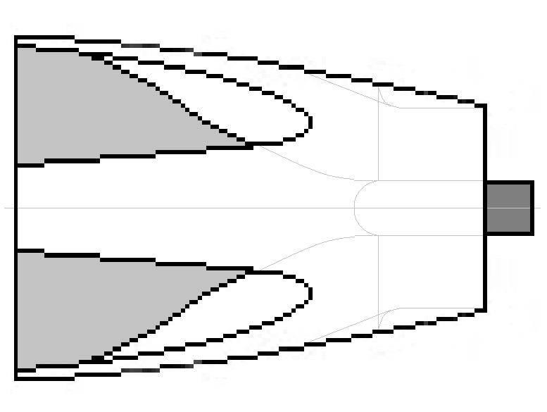
This is the ultimate aim. An RC 'winged' V-2 (A4b) as an EDF and in Depron.

EDF right at the back with a very short duct to give maximum static thrust.
It should be light enough to hand launch and belly land.
The issue is the EDF will have to obtain all its air from cheat holes and these will be positioned on the rear of the fuselage so will in effect be somewhat shielded from the direct airflow. Ultimately it would be nice to have these covered with spring loaded doors.
Before embarking on the full build I intend to make just the rear section with the EDF and cheat holes to determine the best method of construction and the effect the cheat holes have on the static thrust.
Something like this:
First the inner cone, planked in 2mm Depron.

At this point it became obvious that to keep each inlet smooth and of the right cross sectional area would require them to have quite a complex shape. Whilst I could visualise the require shape I could not see a way of actually making them in planked Depron.
Unfortunately the most likely solution would not use the inner cone shape that I had already made!
Rather than start again I decided to continue and finish the test duct but with a simple inlet duct shape that would be relatively easy to make however they would be less that ideal aerodynamically.
Although a bit disappointed at my construction failure I can take some comfort that the EDF and its inlet is the biggest unknown part of this build so 'development' at this stage should improve the chances of it actually flying reasonably well.
First a recap on progress so far.
This is the ultimate aim. An RC 'winged' V-2 (A4b) as an EDF and in Depron.
EDF right at the back with a very short duct to give maximum static thrust.
It should be light enough to hand launch and belly land.
The issue is the EDF will have to obtain all its air from cheat holes and these will be positioned on the rear of the fuselage so will in effect be somewhat shielded from the direct airflow. Ultimately it would be nice to have these covered with spring loaded doors.
Before embarking on the full build I intend to make just the rear section with the EDF and cheat holes to determine the best method of construction and the effect the cheat holes have on the static thrust.
Something like this:
First the inner cone, planked in 2mm Depron.
At this point it became obvious that to keep each inlet smooth and of the right cross sectional area would require them to have quite a complex shape. Whilst I could visualise the require shape I could not see a way of actually making them in planked Depron.
Unfortunately the most likely solution would not use the inner cone shape that I had already made!
Rather than start again I decided to continue and finish the test duct but with a simple inlet duct shape that would be relatively easy to make however they would be less that ideal aerodynamically.
Although a bit disappointed at my construction failure I can take some comfort that the EDF and its inlet is the biggest unknown part of this build so 'development' at this stage should improve the chances of it actually flying reasonably well.
Last edit: 14 Nov 2015 00:35 by Quorneng.
Thanks: Klipkopwildlife, THE BLACKBIRD, old fart, boz
Please Log in or Create an account to join the conversation.
- Ex-Member
- User
-

Less
More
- Thank you received: 0
14 Nov 2015 07:05 #2
by Ex-Member
Replied by Ex-Member on topic Aggregate A9 (A4b)
be great to see this flying.
you do pick some difficult subjects Simon.
you do pick some difficult subjects Simon.
Please Log in or Create an account to join the conversation.
- Quorneng
-
Topic Author
- Offline
- Forum Master
-
Less
More
- Posts: 9436
- Thank you received: 19043
14 Nov 2015 18:36 #3
by Quorneng
Replied by Quorneng on topic Aggregate A9 (A4b)
Despite my reservation the test section is coming along quite nicely.
First 4 supports.

These represent the outside profile and provide location for the EDF.
The first of the exterior planks.

More skin planking around the intake opening. The planks continue right to the end of the fan body.

A view down one of the four identical intakes.
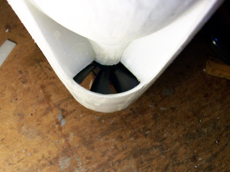
The intakes are bigger than strictly necessary and their internal shape is not ideal but building this has certainly given me some ideas on where to improve their shape and more important how to build them!
First 4 supports.
These represent the outside profile and provide location for the EDF.
The first of the exterior planks.
More skin planking around the intake opening. The planks continue right to the end of the fan body.
A view down one of the four identical intakes.
The intakes are bigger than strictly necessary and their internal shape is not ideal but building this has certainly given me some ideas on where to improve their shape and more important how to build them!
Thanks: Klipkopwildlife, Ex-Member, THE BLACKBIRD, old fart, boz
Please Log in or Create an account to join the conversation.
- Ex-Member
- User
-
Less
More
- Thank you received: 0
14 Nov 2015 18:56 #4
by Ex-Member
Replied by Ex-Member on topic Aggregate A9 (A4b)
looking very impressive Simon.
you do like unusual subjects.
you do like unusual subjects.
Please Log in or Create an account to join the conversation.
- Quorneng
-
Topic Author
- Offline
- Forum Master
-
Less
More
- Posts: 9436
- Thank you received: 19043
15 Nov 2015 22:02 #5
by Quorneng
Replied by Quorneng on topic Aggregate A9 (A4b)
The test duct is finished.


However I fear I have 'blown' my only 50 A ESC - when I connected the battery there was a really load crack, I thought at the time is sounded more than the usual capacitor charging. 2 seconds later I noticed the wires were getting warm in my hands! Unplugged the battery pronto.
The reason was obvious. In my temporary electrical 'lash up' just to test the fan was rotating the right way I had a positive to negative connection! :woohoo: . ESC don't like being connected the wrong way. Doh!
I only had a spare 20A ESC but even so it blows a lot of air on just 15A!
Thanks: Klipkopwildlife, The Beard, Ex-Member, THE BLACKBIRD, old fart, boz
Please Log in or Create an account to join the conversation.
- Quorneng
-
Topic Author
- Offline
- Forum Master
-
Less
More
- Posts: 9436
- Thank you received: 19043
17 Nov 2015 00:05 - 17 Nov 2015 00:07 #6
by Quorneng
Replied by Quorneng on topic Aggregate A9 (A4b)
While waiting for the new 40A ESC (the 'cooked' 50A does sometimes work but keeps cutting out even at low power) so I have printed out the complete plan to the required size. The 24" rule gives an idea of its size.

A bit bigger than first thought at 20" span and 48" long. The fuselage is close to 6" diameter at its maximum.
It will likely be built in 3 sections with the nose and middle as half shells over the plan. The tail section will probably be built as a single unit. It will be built first as it is the most complex shape and carries all the mechanical bits!
Still only a guestimate at this stage but with a high C 1800mAh 3s it should come out a bit below 20oz all up.
Last edit: 17 Nov 2015 00:07 by Quorneng.
Thanks: Klipkopwildlife, THE BLACKBIRD, old fart
Please Log in or Create an account to join the conversation.
- Ex-Member
- User
-
Less
More
- Thank you received: 0
17 Nov 2015 07:50 #7
by Ex-Member
Replied by Ex-Member on topic Aggregate A9 (A4b)
Looking good Q....I do like your style and the way you go about building these machines! Have you ever thought about or tried to get your work published in the model mags?
A quick question, have you thought about how you're going to launch it. With a 6" dia fus, it may be a bit difficult to get your fingers to grip.
A quick question, have you thought about how you're going to launch it. With a 6" dia fus, it may be a bit difficult to get your fingers to grip.
Please Log in or Create an account to join the conversation.
- Ex-Member
- User
-
Less
More
- Thank you received: 0
17 Nov 2015 09:30 #8
by Ex-Member
Replied by Ex-Member on topic Aggregate A9 (A4b)
i would have thought a vertical take off and then transition into normal flight.
lovely idea simon, hope it all works ok
lovely idea simon, hope it all works ok
Please Log in or Create an account to join the conversation.
- Quorneng
-
Topic Author
- Offline
- Forum Master
-
Less
More
- Posts: 9436
- Thank you received: 19043
17 Nov 2015 12:37 #9
by Quorneng
Replied by Quorneng on topic Aggregate A9 (A4b)
Andy
Launching is an issue. This is the method I use on my V-1 which by chance is also 6" diameter.
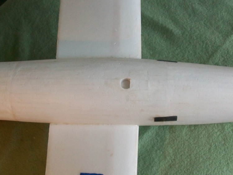
The shallow reinforced finger hole is just behind the COG, the sand paper finger grips are a bit in front so it is held like this.

Note I launch left handed although it would work just a well in the other hand.
Publish? May be!
Before I start work on the 'flight' version of the tail end I have been looking at the possibility of spring loaded doors.
The current arrangement of the test duct means the inlets are significantly over size. As it 'submerges' into the fuselage each has an area of just over 1700 mm sq 'normal' to the airflow. At close to 7000 mm sq for the four gives a total area that is over twice the FSA. :huh:
This suggest there is some room to alter the shape of the inlet duct to allow a long single door to both fit the fuselage aperture and hinge down to give a reasonably smooth path to the duct with an area of 1/4 the FSA.
I will modify one of the inlets on the test duct to experiment.
I have drawn the over hung elevons to the scale size (although I am a bit dubious of the accuracy of some of the 3 views) but they look very large and delicate for something that could achieve close to 2000 mph! :woohoo: Perhaps I should not complain as such generous proportions will be a distinct advantage at 30mph!
I have found this period photo.

It would seem to confirm each elevon was indeed something like the drawing.
Models of the A4b were tested in the supersonic wind tunnel at Peenemunde.
Launching is an issue. This is the method I use on my V-1 which by chance is also 6" diameter.
The shallow reinforced finger hole is just behind the COG, the sand paper finger grips are a bit in front so it is held like this.
Note I launch left handed although it would work just a well in the other hand.
Publish? May be!
Before I start work on the 'flight' version of the tail end I have been looking at the possibility of spring loaded doors.
The current arrangement of the test duct means the inlets are significantly over size. As it 'submerges' into the fuselage each has an area of just over 1700 mm sq 'normal' to the airflow. At close to 7000 mm sq for the four gives a total area that is over twice the FSA. :huh:
This suggest there is some room to alter the shape of the inlet duct to allow a long single door to both fit the fuselage aperture and hinge down to give a reasonably smooth path to the duct with an area of 1/4 the FSA.
I will modify one of the inlets on the test duct to experiment.
I have drawn the over hung elevons to the scale size (although I am a bit dubious of the accuracy of some of the 3 views) but they look very large and delicate for something that could achieve close to 2000 mph! :woohoo: Perhaps I should not complain as such generous proportions will be a distinct advantage at 30mph!
I have found this period photo.
It would seem to confirm each elevon was indeed something like the drawing.
Models of the A4b were tested in the supersonic wind tunnel at Peenemunde.
Thanks: Klipkopwildlife, Ex-Member, old fart
Please Log in or Create an account to join the conversation.
- Quorneng
-
Topic Author
- Offline
- Forum Master
-
Less
More
- Posts: 9436
- Thank you received: 19043
18 Nov 2015 00:49 - 18 Nov 2015 00:50 #10
by Quorneng
Replied by Quorneng on topic Aggregate A9 (A4b)
Until the new ESC arrives I cannot run the test duct at full power so rather than do nothing I have started the nose of the 'flight' version..
A slight change in plan as this bit will now be built in one piece - vertically - as I did with the V-1.
The 9 formers.

All but the smallest are internally flanged rings to give the best strength to weight ratio.
There will be a lot on empty space inside!
A slight change in plan as this bit will now be built in one piece - vertically - as I did with the V-1.
The 9 formers.
All but the smallest are internally flanged rings to give the best strength to weight ratio.
There will be a lot on empty space inside!
Last edit: 18 Nov 2015 00:50 by Quorneng.
Thanks: Klipkopwildlife, Ex-Member, THE BLACKBIRD, old fart
Please Log in or Create an account to join the conversation.
- one tenor
-

- Offline
- Forum Veteran
-

- johnpcalex@gmail.com
18 Nov 2015 03:07 #11
by one tenor
Anything will fly given enough power
Replied by one tenor on topic Aggregate A9 (A4b)
Have you seen this
www.astronautix.com/lvs/a4b.htm There is more on the net if you Google or whatever ..
www.astronautix.com/lvs/a4b.htm There is more on the net if you Google or whatever ..
Anything will fly given enough power
Please Log in or Create an account to join the conversation.
- Quorneng
-
Topic Author
- Offline
- Forum Master
-
Less
More
- Posts: 9436
- Thank you received: 19043
19 Nov 2015 00:17 #12
by Quorneng
Replied by Quorneng on topic Aggregate A9 (A4b)
one tenor
Yes I had seen it. Really interesting. I tend to Google quite a bit before I build anything scale.
This is no way to build a plane! :woohoo:

Terribly delicate and wobbly to start with.
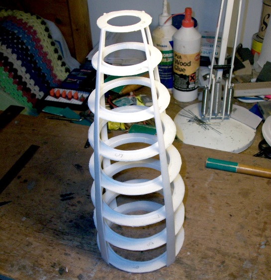
But it gets progressively stiffer as the planking proceeds and it is very light!
Yes I had seen it. Really interesting. I tend to Google quite a bit before I build anything scale.
This is no way to build a plane! :woohoo:
Terribly delicate and wobbly to start with.
But it gets progressively stiffer as the planking proceeds and it is very light!
Thanks: Klipkopwildlife, Ex-Member, THE BLACKBIRD, old fart
Please Log in or Create an account to join the conversation.
- Quorneng
-
Topic Author
- Offline
- Forum Master
-
Less
More
- Posts: 9436
- Thank you received: 19043
20 Nov 2015 22:53 - 20 Nov 2015 22:56 #13
by Quorneng
Replied by Quorneng on topic Aggregate A9 (A4b)
With the main nose section planking (all 28 of them!) complete, next is the nose cone.

Much easier as it has a constant taper so each plank is simply a straight edged triangle.
The full nose section represents just over 1/3 of the total fuselage length.
I think the wings next. One piece skin tip to tip?
Much easier as it has a constant taper so each plank is simply a straight edged triangle.
The full nose section represents just over 1/3 of the total fuselage length.
I think the wings next. One piece skin tip to tip?
Last edit: 20 Nov 2015 22:56 by Quorneng.
Thanks: Klipkopwildlife, Ex-Member, THE BLACKBIRD, old fart
Please Log in or Create an account to join the conversation.
- Quorneng
-
Topic Author
- Offline
- Forum Master
-
Less
More
- Posts: 9436
- Thank you received: 19043
21 Nov 2015 23:19 - 21 Nov 2015 23:21 #14
by Quorneng
Replied by Quorneng on topic Aggregate A9 (A4b)
The nose section complete.

It weighs 24g (0.83 oz)
When the glue is fully hard It will need a bit of filling and gentle sanding.
As far as I have been able to find out the wings were of a typical 'supersonic' section, sharp leading edge, fully symmetrical, maximum thickness near to 50% and pretty thin so that is what mine will have!
A one piece 2mm Depron skins top and bottom.
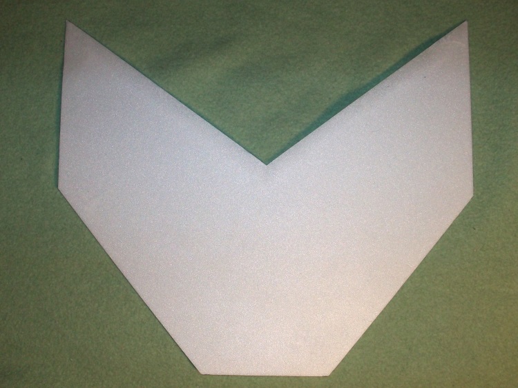
As a full 'stressed skin' structure it has no spars just Depron spacers and only 3 ribs!

It weighs 24g (0.83 oz)
When the glue is fully hard It will need a bit of filling and gentle sanding.
As far as I have been able to find out the wings were of a typical 'supersonic' section, sharp leading edge, fully symmetrical, maximum thickness near to 50% and pretty thin so that is what mine will have!
A one piece 2mm Depron skins top and bottom.
As a full 'stressed skin' structure it has no spars just Depron spacers and only 3 ribs!
Last edit: 21 Nov 2015 23:21 by Quorneng.
Thanks: Klipkopwildlife, Ex-Member, THE BLACKBIRD, old fart, Ralpharr2001
Please Log in or Create an account to join the conversation.
- THE BLACKBIRD
-

- Offline
- Forum Master
-
Less
More
- Posts: 6368
- Thank you received: 10844
22 Nov 2015 11:35 #15
by THE BLACKBIRD
Replied by THE BLACKBIRD on topic Aggregate A9 (A4b)
Bloody incredible and ingenious building Simon, you never fail to amaze me with your builds
Fantastic
Fantastic
Please Log in or Create an account to join the conversation.
Time to create page: 2.030 seconds