
- Posts: 757
- Thank you received: 1164
3D printed props
- jon.in.swansea
-
 Topic Author
- Offline
- Elite Member
-

Less
More
26 Jan 2022 15:38 #1
by jon.in.swansea
3D printed props was created by jon.in.swansea
As a novice flyer I find that props are consumables. An APC prop is a beautiful thing but a) beauty costs, b) they can take a while to get assuming there is stock. I have a Prusa Mini and although I would not design my own prop I found some likely candidates. I test printed various STL files and tested them on my
 shielded thrust rig to see how they performed. I settled down on two variants - both derived from an 8x4.5 - one was described as a 'slow prop' and it is noticeably beefier and wider. The other is seen in the montage below.
Hints: rotate the prop for printing. If you print with the shaft vertical you have a lot of cleaning to do. The Prusa slicer software allows one to paint on support locations (see the blue dots on the upper left). This results in just enough support. If you ask for supports 'from the build plate' you get lots more and they are difficult to remove. I increase the support Z gap by 0.05mm and the supports tend to pull off easily.
Light sanding with P600 is usually all that is required to tidy the edges. I paint a bit of correction fluid on the front for ease of identification in the field. As printed these beasties are not quite balanced. I have a simple rig for balancing and I find that adding a bit of electrical tape is faster and works as well for me as sanding down for getting a balance.
I only had one pop on me at an early stage of learning how to print and balance. I have a habit of testing every other prop I print - it goes on the model and gets ~2/3 throttle. I use prop-savers - some motors come with them, otherwise I have a prop-saver that I print as well (adapting as needed for the motor shaft and the prop). I keep a 2-3 spares in my field box - especially if it is a maiden session or I have not quite got the feel of the model. Sometimes I will swop the one shown in the photos with the 'slow' variant to see if that has a better feel on the day.
I am happy to share the STL file and or the Prusa .3mf file but those are rather large for the upload facility. Suggestions? -Jon
Hints: rotate the prop for printing. If you print with the shaft vertical you have a lot of cleaning to do. The Prusa slicer software allows one to paint on support locations (see the blue dots on the upper left). This results in just enough support. If you ask for supports 'from the build plate' you get lots more and they are difficult to remove. I increase the support Z gap by 0.05mm and the supports tend to pull off easily.
Light sanding with P600 is usually all that is required to tidy the edges. I paint a bit of correction fluid on the front for ease of identification in the field. As printed these beasties are not quite balanced. I have a simple rig for balancing and I find that adding a bit of electrical tape is faster and works as well for me as sanding down for getting a balance.
I only had one pop on me at an early stage of learning how to print and balance. I have a habit of testing every other prop I print - it goes on the model and gets ~2/3 throttle. I use prop-savers - some motors come with them, otherwise I have a prop-saver that I print as well (adapting as needed for the motor shaft and the prop). I keep a 2-3 spares in my field box - especially if it is a maiden session or I have not quite got the feel of the model. Sometimes I will swop the one shown in the photos with the 'slow' variant to see if that has a better feel on the day.
I am happy to share the STL file and or the Prusa .3mf file but those are rather large for the upload facility. Suggestions? -Jon
Attachments:
Thanks: Klipkopwildlife
Please Log in or Create an account to join the conversation.
- Eric
-

- Offline
- Moderator
-

Less
More
- Posts: 15406
- Thank you received: 14306
26 Jan 2022 15:55 #2
by Eric
if you are calm and collected when all about you are going berserk - you've missed something important!
Replied by Eric on topic 3D printed props
I don't need to say Be very careful - but I will! A prop is under very high gyroscopic and torsional stress, at flying rpm's, and you do not want to be in the way of a loose knife-blade travelling at a couple of hundred mph!
if you are calm and collected when all about you are going berserk - you've missed something important!
Thanks: Klipkopwildlife
Please Log in or Create an account to join the conversation.
- Klipkopwildlife
-

- Offline
- Administrator
-

- I'm supposed to be retired!
26 Jan 2022 16:55 #3
by Klipkopwildlife
Do it now, you may never get another chance
Replied by Klipkopwildlife on topic 3D printed props
I'd be interested to see what they read on a Watt meter compared to a store bought one.
Do it now, you may never get another chance
Please Log in or Create an account to join the conversation.
- jon.in.swansea
-
Topic Author
- Offline
- Elite Member
-
Less
More
- Posts: 757
- Thank you received: 1164
26 Jan 2022 18:07 #4
by jon.in.swansea
Replied by jon.in.swansea on topic 3D printed props
In my early testing on the thrust checker.... I went one 'notch' at a time on the Futaba throttle. Half throttle is about 10 notches out of 18-20 on the stick. I don't have a Watt meter so can only report the thrust. I used the same
APC 7x4 (178mm) 2cell ~half throttle = 86g top = 190g thrust,
3cell half throttle = 122g top = 350g thrust
175mm 'slow-fat' printed prop 2cell ~half 84g top = 190g thrust,
3cell ~half 134 top = 272g thrust
186mm 'slow-fat' printed prop 2cell ~half 82g top = 176g thrust,
3cell ~half 130 top = 300g thrust
180mm normal 8x4.5 printed prop 2cell ~half 48g. top = 134g
3cell ~half 80g top = 244g
195mm normal 8x4.5 printed prop 2cell ~half 68g. top = 174g
3cell ~half 126g top = 290g
The 180 normal printed 8x4.5 does not do so well at upper revs. The 'slow-fat' wins on thrust if I am running on a 2cell (saves some weight. I like to start with 2cell and then move to 3cell after I am a bit more comfortable with flight characteristics). With printed props I rarely go much over half throttle - briefly on launch. The exception are pushers as the prop diameter is less and they seem underpowered.
The APC is quieter and provides more thrust.

-Jon
APC 7x4 (178mm) 2cell ~half throttle = 86g top = 190g thrust,
3cell half throttle = 122g top = 350g thrust
175mm 'slow-fat' printed prop 2cell ~half 84g top = 190g thrust,
3cell ~half 134 top = 272g thrust
186mm 'slow-fat' printed prop 2cell ~half 82g top = 176g thrust,
3cell ~half 130 top = 300g thrust
180mm normal 8x4.5 printed prop 2cell ~half 48g. top = 134g
3cell ~half 80g top = 244g
195mm normal 8x4.5 printed prop 2cell ~half 68g. top = 174g
3cell ~half 126g top = 290g
The 180 normal printed 8x4.5 does not do so well at upper revs. The 'slow-fat' wins on thrust if I am running on a 2cell (saves some weight. I like to start with 2cell and then move to 3cell after I am a bit more comfortable with flight characteristics). With printed props I rarely go much over half throttle - briefly on launch. The exception are pushers as the prop diameter is less and they seem underpowered.
The APC is quieter and provides more thrust.
-Jon
Attachments:
Thanks: Klipkopwildlife
Please Log in or Create an account to join the conversation.
- paul d
-
- Offline
- Forum Veteran
-

Less
More
- Posts: 2074
- Thank you received: 2292
26 Jan 2022 18:33 #5
by paul d
balsa is best.
Replied by paul d on topic 3D printed props
Nice rig Jon! And a very interesting post, there was a article in aeromodeller recently concerning printing props, equally very interesting, being a predominantly diesel user and hence hand start everything I hate apc props, to bloody sharp!
balsa is best.
Thanks: Klipkopwildlife
Please Log in or Create an account to join the conversation.
- Eric
-
- Offline
- Moderator
-
Less
More
- Posts: 15406
- Thank you received: 14306
26 Jan 2022 21:31 #6
by Eric
if you are calm and collected when all about you are going berserk - you've missed something important!
Replied by Eric on topic 3D printed props
too bloody sharp!
A bit of fine glasscloth is your friend! Apply gently to the trailing edge!
A bit of fine glasscloth is your friend! Apply gently to the trailing edge!
if you are calm and collected when all about you are going berserk - you've missed something important!
Thanks: Klipkopwildlife
Please Log in or Create an account to join the conversation.
- Quorneng
-

- Offline
- Forum Master
-

Less
More
- Posts: 10058
- Thank you received: 19043
26 Jan 2022 22:54 #7
by Quorneng
Replied by Quorneng on topic 3D printed props
jon
Interesting but the really important figure for most electric flying is the thrust/W figure (thrust efficiency) rather than simply the maximum thrust obtainable. You do need a Watt meter to determine it.
It would be most interesting to compare the efficiency of a printed prop against a moulded one.
With electric you can't really afford to 'squander' power, the battery is just too heavy, whereas with IC you can and in practise have to simply to make the prop strong enough to withstand the cyclic loads the engine generates.
Interesting but the really important figure for most electric flying is the thrust/W figure (thrust efficiency) rather than simply the maximum thrust obtainable. You do need a Watt meter to determine it.
It would be most interesting to compare the efficiency of a printed prop against a moulded one.
With electric you can't really afford to 'squander' power, the battery is just too heavy, whereas with IC you can and in practise have to simply to make the prop strong enough to withstand the cyclic loads the engine generates.
Thanks: Eric, Klipkopwildlife
Please Log in or Create an account to join the conversation.
- Klipkopwildlife
-
- Offline
- Administrator
-
- I'm supposed to be retired!
27 Jan 2022 07:23 #8
by Klipkopwildlife
Do it now, you may never get another chance
Replied by Klipkopwildlife on topic 3D printed props
Yes Jon, Simon is right, a Watt meter (
HERE
) is the best option, although a DC clamp meter may have more uses. If you decide to use a DC clamp meter just multiply the Amps by 11.5 for an approximate (but close enough) Wattage. For your kind of flying you're looking for about 100W/lb at full throttle.
Do it now, you may never get another chance
Thanks: Eric
Please Log in or Create an account to join the conversation.
- Eric
-
- Offline
- Moderator
-
Less
More
- Posts: 15406
- Thank you received: 14306
27 Jan 2022 08:08 - 27 Jan 2022 08:10 #9
by Eric
if you are calm and collected when all about you are going berserk - you've missed something important!
Replied by Eric on topic 3D printed props
Jon put - I don't have a Watt meter - - I missed that!
As Simon put, this is a vital tool for electric flying, as it tells you whether you are asking too much from the motor/battery/speed controller combi.
Used with your thrust gauge, it will show how much tractive effort the prop is putting in AND how hard the motor etc are working to achieve that.
In turn, that will give you an indication of useful flying time for that combine, and if something is working at 100%, and about to release the magic smoke!
-
In case you hadn't realised it, a motor has a designed rpm/volt figure, the kv, and if loaded ( with a prop, etc) it will ask for more and more amps from the battery/speedo until it achieves this, or something fails - the motor windings melt, the speedo goes pop, or the battery simply cannot deliver, as it exceeds it's max safe current. (the C rating)
Then if that happens, you could have a nice bonfire on your work-bench.
It is generally accepted that the speed controller should be able to deliver between 25 and 50% MORE than the motor could ever demand, to avoid it becoming a very expensive fuse!
it's a balancing act.
As Simon put, this is a vital tool for electric flying, as it tells you whether you are asking too much from the motor/battery/speed controller combi.
Used with your thrust gauge, it will show how much tractive effort the prop is putting in AND how hard the motor etc are working to achieve that.
In turn, that will give you an indication of useful flying time for that combine, and if something is working at 100%, and about to release the magic smoke!
-
In case you hadn't realised it, a motor has a designed rpm/volt figure, the kv, and if loaded ( with a prop, etc) it will ask for more and more amps from the battery/speedo until it achieves this, or something fails - the motor windings melt, the speedo goes pop, or the battery simply cannot deliver, as it exceeds it's max safe current. (the C rating)
Then if that happens, you could have a nice bonfire on your work-bench.
It is generally accepted that the speed controller should be able to deliver between 25 and 50% MORE than the motor could ever demand, to avoid it becoming a very expensive fuse!
it's a balancing act.
if you are calm and collected when all about you are going berserk - you've missed something important!
Last edit: 27 Jan 2022 08:10 by Eric. Reason: added a comment
Thanks: Klipkopwildlife
Please Log in or Create an account to join the conversation.
- jon.in.swansea
-
Topic Author
- Offline
- Elite Member
-
Less
More
- Posts: 757
- Thank you received: 1164
27 Jan 2022 18:40 #10
by jon.in.swansea
Replied by jon.in.swansea on topic 3D printed props
I had a quick look at DC meters. Goodness so many have complaints about wild inaccuracies. I picked one that have fewer complaints and we shall see what happens. I will solder on some T30 connectors.... I am assuming black-to-black, red-to-red and it should go between the battery and the ESC. If anyone has a photo of a proper setup I would be interested.... -Jon
Thanks: Klipkopwildlife
Please Log in or Create an account to join the conversation.
- Eric
-
- Offline
- Moderator
-
Less
More
- Posts: 15406
- Thank you received: 14306
27 Jan 2022 19:03 #11
by Eric
if you are calm and collected when all about you are going berserk - you've missed something important!
Replied by Eric on topic 3D printed props
You only have to ask!
Obviously the components are not connected, but are laid out as if they were. The white cone represents the receiver, and the speed controller is plugged in to the pins marked 'throttle'.

Obviously the components are not connected, but are laid out as if they were. The white cone represents the receiver, and the speed controller is plugged in to the pins marked 'throttle'.
if you are calm and collected when all about you are going berserk - you've missed something important!
Attachments:
Thanks: Klipkopwildlife
Please Log in or Create an account to join the conversation.
- Eric
-
- Offline
- Moderator
-
Less
More
- Posts: 15406
- Thank you received: 14306
27 Jan 2022 20:47 #12
by Eric
if you are calm and collected when all about you are going berserk - you've missed something important!
Replied by Eric on topic 3D printed props
p,s, the wattmeter is not necessary for actually flying the model, just for testing and checking on the ground. The only time you would need to re-check is if you have changed something, ie the motor or prop!
if you are calm and collected when all about you are going berserk - you've missed something important!
Thanks: Klipkopwildlife
Please Log in or Create an account to join the conversation.
- Quorneng
-
- Offline
- Forum Master
-
Less
More
- Posts: 10058
- Thank you received: 19043
27 Jan 2022 21:31 - 27 Jan 2022 21:32 #13
by Quorneng
Replied by Quorneng on topic 3D printed props
Jon
My Watt meter set up and its actually running!

Note the use of a servo tester to work the ESC to run the motor. Very simple. No radio is required. I use Deans connectors.
A close up of the Watt meter.

Running at low power, 0.42A, 8.17V (a charged 2s) using 3.4W.
This rig is for testing the amps and the balance of props. It does measure thrust.
My Watt meter set up and its actually running!
Note the use of a servo tester to work the ESC to run the motor. Very simple. No radio is required. I use Deans connectors.
A close up of the Watt meter.
Running at low power, 0.42A, 8.17V (a charged 2s) using 3.4W.
This rig is for testing the amps and the balance of props. It does measure thrust.
Attachments:
Last edit: 27 Jan 2022 21:32 by Quorneng.
Thanks: Eric, Klipkopwildlife
Please Log in or Create an account to join the conversation.
- jon.in.swansea
-
Topic Author
- Offline
- Elite Member
-
Less
More
- Posts: 757
- Thank you received: 1164
30 Jan 2022 18:11 #14
by jon.in.swansea
Replied by jon.in.swansea on topic 3D printed props
Brilliant. Thanks for the clear images and descriptions. I might try using my servo tester rather than the Futaba for my next session. There has been a run of very windy days here that has kept me from heading out to the field so that suggests that I use the time for these background tasks.
Thanks: Klipkopwildlife
Please Log in or Create an account to join the conversation.
- Quorneng
-
- Offline
- Forum Master
-
Less
More
- Posts: 10058
- Thank you received: 19043
30 Jan 2022 22:09 #15
by Quorneng
Replied by Quorneng on topic 3D printed props
jon
If you are using that type of servo tester note its servo signal output is connected to both the input and output centre pins so although the ESC is connected to the "input" side, so it powers the servo tester, the tester also provides a 'signal' that will control the ESC.
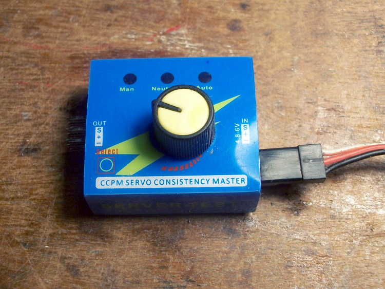
Just be careful not to select "auto" as it will then cycle the motor repeatedly from zero to full throttle.
If you are using that type of servo tester note its servo signal output is connected to both the input and output centre pins so although the ESC is connected to the "input" side, so it powers the servo tester, the tester also provides a 'signal' that will control the ESC.
Just be careful not to select "auto" as it will then cycle the motor repeatedly from zero to full throttle.
Attachments:
Thanks: Klipkopwildlife, jon.in.swansea
Please Log in or Create an account to join the conversation.
Time to create page: 0.597 seconds