
- Posts: 158
- Thank you received: 422
- Forum
- Forum Categories
- Technical Stuff, Radio Gear, Electronics.
- Electronic Project Easy Build - Servo Tester
Electronic Project Easy Build - Servo Tester
- sydc
-
 Topic Author
- Offline
- Premium Member
-

Less
More
26 Apr 2014 14:54 - 26 Apr 2014 15:17 #1
by sydc
Electronic Project Easy Build - Servo Tester was created by sydc
Project: RC Servo Controller
Introduction.
The RC Servo controller is a device that can be used to control the functions of a RC Servo without the need to operate the radio receiver and transmitter. This device can be easily built for approximately £15 without any knowledge of electronics although this would be an advantage together with the ability to solder components into a circuit matrix board.
Servo Basics.
Since the early 1990's servos have used a de-facto standard pulse width modulation technique to control the position of the output shaft. The pulse is fed to the servo via a control line. The control line does not supply power to the motor directly it is an input to a control chip inside the servo and as such it does not have to supply much current to the servo as separate power wires supplies the power to the servo. The ground for power is also used as the ground for the control line.

Note: 1000ms (milliseconds) = 1 second.
In FIGURE 1 you can see the timing relationship between the pulse width and servo position. The servo's control logic needs to see at least a one millisecond pulse before the actual pulse width modulated (PWM) signal. The control part of the signal is broken down into the 1ms minimum time, the 1ms PWM signal, and a 20ms delay. This delay is not as critical as the other parts of the timing signal. It is essentially the dead time between control signals. If you repeat the control signals too quickly (i.e. 10ms delay) the servo will buzz and jitter. If you repeat the control signals too slow (i.e. 70ms delay) the servo will shut off between signals and its position will not remain constant.
Servo Controller Circuit.
If you don't have a radio transmitter and receiver handy you won't have any way of generating the control signal for the servo. A simple circuit FIGURE 2 using a 12F675 PIC (Peripheral Interface Controller) can generate the signals required.

When switch S1 is depressed this pulls pin 6 of the 12F675 PIC down to 0 volts, this will produce a pulse width of 1.5ms and centre the servo, adjustment of the potentiometer R5 will vary the pulse width from 1ms to 2ms changing the servo position from full left travel to full right. Likewise when S2 is depressed this pulls pin 4 of the 12F675 PIC down to 0 volts, this will produce a constantly varying pulse width between 1ms and 2ms, the speed of the travel of the servo may be increased or decreased with the variation of potentiometer R5. This is useful for testing or ‘bedding in’ servos.
Components Required.
The following components are required for the project.
1 - 100nF 100v Dipped Ceramic Capacitor 882 - 061
2 - 27pF 100v Ceramic Mini Disc Capacitor 872 - 018
2 - 10kΩ 0.25w 1% Film Resistor 907 - 310e
1 - 1kΩ 0.25w 1% Film Resistor 907 - 210e
1 - 4.7kΩ Linear 16mm PCB Mounting Pot 947 - 247
1 - BZX85 4V7 1.3w Zener Diode 726 - 047
1 - 82R 0.5w Carbon Film Resistor 910 - 082e
1 - Stripboard 80x100mm 0.1” 335 - 020
1 - 15x20mm Ø Control Knob 060 - 112
1 - G302 Dark Grey ABS Enclosure 64x58x35mm 400 - 602
1 - 8 pin Dual In-Line IC Socket 0.3” 110 - 082
1 - 10MHz Quartz Crystal HC-49/U Case 760 -100
1 - 3 Way Single Row Header – Straight 111 - 103
1 - 250ma Push to Make 6mm Ø Button - Black 212 - 460
1 - 250ma Push to Make 6mm Ø Button – Red 212 - 462
All the above components are available from ESR Electronic Components Ltd., web address www.esr.co.uk order by phone with e-mail confirmation This email address is being protected from spambots. You need JavaScript enabled to view it. telephone number 0845 2514363. The column on the far right of the component list shows the ESR spares number.
Other parts required.
1 - Futaba 150mm Extension Cable
1 - Futaba ‘Y’ Lead
1 - 12F675 8 bit PIC (Peripheral Interface Controller)
I will supply the source code for anyone who wants to program the PIC themselves. The 12F675 is widely available at electronics outlets.
Tools Required.
Junior hacksaw
20 – 25 watt miniature soldering iron
60-40 22swg resin core electronic solder
3.2mm (⅛”) diameter HSS drill bit
8mm diameter HSS drill bit
7mm diameter HSS drill bit
5mm diameter HSS drill bit
Matrix Board.
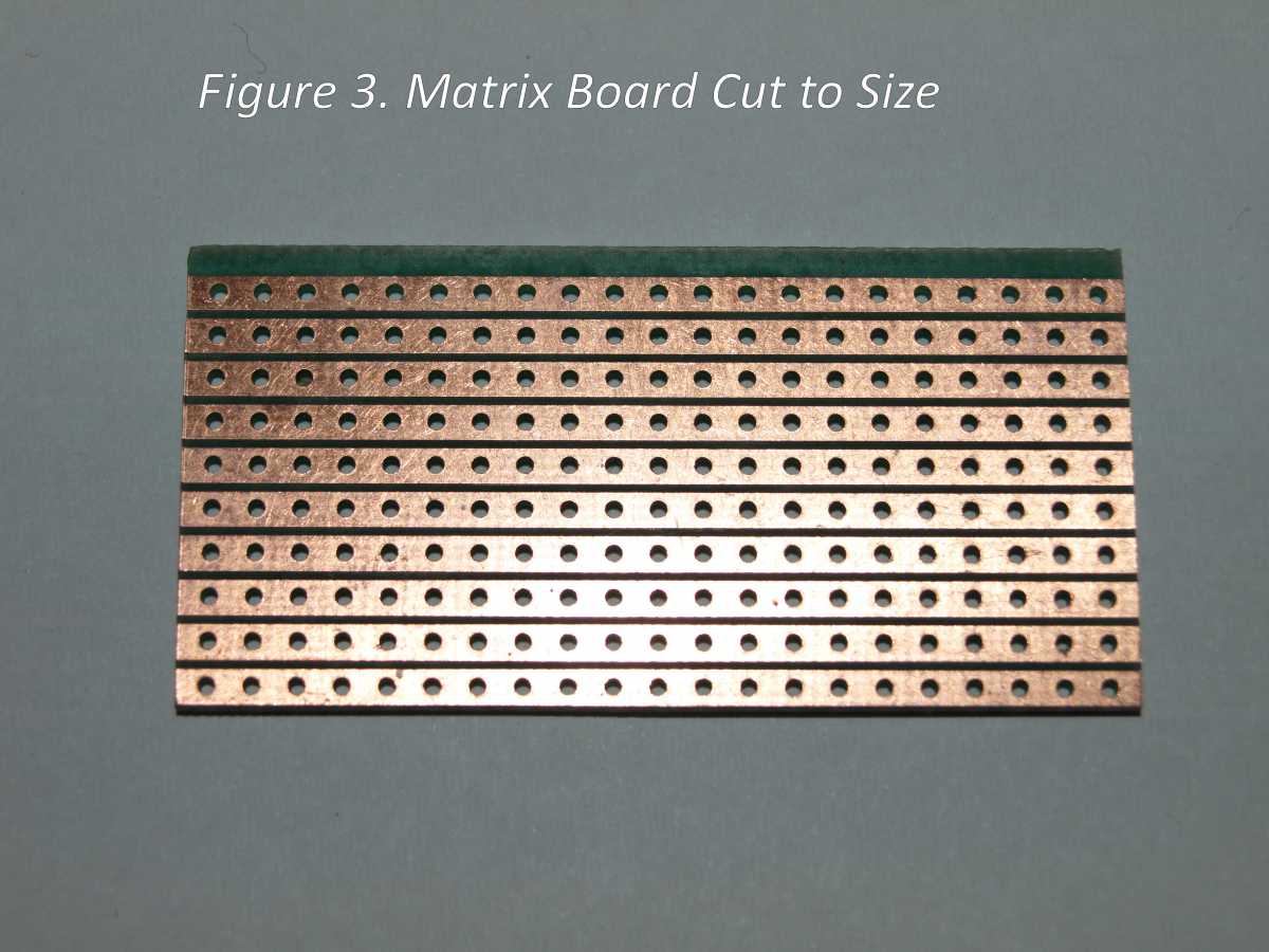
Cut the matrix board so that the board has 10 rows of copper track with 21 columns of holes. The PC board should measure 27mm x 54mm as shown in FIGURE 3.
The circuit board will require the copper tracks to be cut in pre-defined positions on the matrix board. FIGURE 4 shows the points on the matrix board where the copper track will be broken, this is achieved by using the 3.2mm HSS twist drill to drill out the copper track. The diagram shows the holes in the matrix board from the component side, so it is very important that the correct point on the matrix board is drilled out.

Note the points at which the copper track will be broken are highlighted in black and are located as follows;
The copper track between points A9 and A10 must be cut with a sharp scalpel knife or a small Dremel type drill but care must be taken not to damage the adjacent copper track. Points A12, F8, F11, F15, G11, G16, H7, H10, H17, I10, I13 and I16 may be removed with the 3.2mm HSS drill.
Note: The diagram is viewed from the component side of the matrix board. Make absolutely sure that the correct track points are removed.
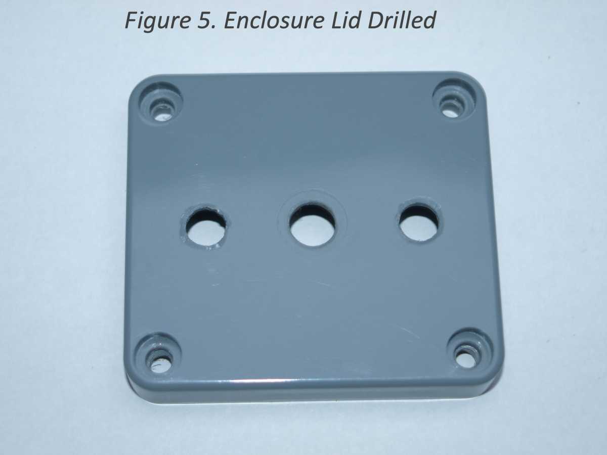
Drill the centre hole in the lid of the enclosure with the 8mm HSS drill making sure that the hole is located exactly in the centre of the lid. There is a marking on the underside of the lid indicating the centre. The other two holes either side of the centre hole are drilled with a 7mm diameter drill 13mm from the outer edge of the lid on the centre line. See FIGURE 5.
Test fit the matrix board into the enclosure lid by first mounting the potentiometer R4 into the matrix board with the centre pin of the potentiometer located at position A11, DO NOT SOLDER potentiometer into matrix board as yet.
Adjustments to the matrix board may have to be made so that the board fits into the lid without undue force.
The potentiometer may now be removed from the matrix board to enable the wire links to be soldered in to the board. See FIGURE 6 for the positions of the wire links in to matrix board. 24swg (small wire gauge) or 1/0.5mm solid wire (same as used for telephone extensions) may be used for the links. Solder the wire links into the following locations B7 to I7, A8 to B8, A10 to F10, I11 to J11, H15 to I15, B18 to G18, G19 to H19 and finally A20 to J20. Hint: you may find the wire links easier to solder in place if the wire is held in place with a small piece of masking tape, this prevents the wire from falling out of the matrix board when the board is turned over to the copper print side. The masking tape is removed once the link is soldered into position.
Once the wire links are in place double check their positions are correct before the components are inserted into the matrix board. D1 BZX85C4V7 Zener diode will be the first component to be inserted into the matrix board between locations B4 and J4 (cathode of diode, black ring on one end of encapsulation to J4, marked with a ‘+’ on the matrix board see FIGURE 6), R3 82Ω (colour coded grey, red, black) is next to be added between C5 and J5, R2 10kΩ (colour coded brown, black, black, red) is added between G6 and J6. R1 1kΩ (colour coded brown, black, black, brown) is added between locations D8 and H8. C3 100nF 100v (marked on the body of the capacitor as ‘104’) is added between locations I8 and J8. R4 10kΩ (colour coded brown, black, black, red) is added between F13 and J13. The next component to be added to the matrix board is the crystal Q1 10MHz, care should be taken with this component not to heat the crystal up too much whilst soldering in to the matrix board, it is suggested that two pieces 3mm long of small bore heat shrink tubing is added to each wire leg before mounting on the matrix board, Q1 is added between locations G14 and I14. C2 27pF 100v capacitor (marked as ‘27’ on the component body) should be added between locations G15 and G17, likewise C1 27pF capacitor should be added between locations H16 and H18. The 8 pin DIL (dual in line) IC holder can now be added to the matrix board with pin 1 located at I12, the 3 pin header is added at location B2, C2 and D2. Connecting wires for the two switches S1 and S2 must now be connected to the matrix board. Red, white and black multi strand wire is used, Futaba 150mm extension cables are ideal for this purpose. Remove the plugs from each end and strip the cable into three separate wires and connect one end of the red wire to location F14, the black wire to G2 and finally the white wire to I3. The integrated circuit should now be inserted into the 8 pin DIL socket, the dot on the top of the IC indicates pin 1 and should be located at I12 in the matrix board. The last component to be added to the matrix board is R5 the 4.7kΩ potentiometer with the centre pin located at A11. Refer to FIGURE 6.
Recheck that all components are in the correct location and are correctly orientated.

FIGURE 7 shows the completed matrix board ready to be installed into the enclosure lid.

A hole in the side of the enclosure must now be drilled for the cable entry/access; this hole is 5mm diameter and is located 18mm from ‘long’ edge of the enclosure and 10mm down from the top of the box, where the lid and box join together. See FIGURE 8a and 8b for detail.


The push button switches S1 and S2 should now be fitted to the enclosure lid, it does not matter which way round they are fitted into the lid, take care not to over tighten the mounting nuts as damage to the switch may occur. The matrix board can now be fitted into the lid by mounting potentiometer into the centre hole. The red connecting wire is soldered to a single contact on the switch with the red button (S2); this is the switch for centring the servo position. The black wire is connected to a single contact on the switch with a black button (S1); this switch is for the servo sweep speed. The white lead is connected to the two remaining contacts on S1 and S2. Fit the ‘Y’ lead to the header plug note the orientation, black lead to location B2. See FIGURE 9.

The unit is tested, if all ok the unit is assembled into the enclosure. The knob can now be fitted and the calibration checked. See completed project FIGURE 10.

Programming the PIC.
Using Windows notepad, create a file called ‘Servo675.txt’ then copy and paste the following information in to the text file. This is the PIC code that will be programmed in to the PIC12F675 controller. Once the code is copied into the text file, save the file then rename this file to ‘Servo675.HEX’ this is the file that is loaded into the PIC programmer to ‘burn’ into the PIC programmable ROM. I use a Microchip ‘PicKit2’ for programming my PIC’s.
:020000040000FA
:1000000020288207FE34CD34993466344D343E3492
:10001000303422341A3413340D34093406340434A1
:100020000234013432082B02031D182831082A0239
:1000300008002B083402031D1F282A083302080079
:10004000F520C420CD20B7202A20272021280C1CF1
:1000500027280800B501B601003803193D282C18DF
:100060003428AC185D2843289420A120FF30AD002F
:100070000130AE00AC012C140800B601B5012C18FB
:100080004B28AC18542894202B08AE002A08AD0049
:10009000AC012C15080094201220031843281920C5
:1000A0000318432836280800942082209020371C0B
:1000B0005B28632008007420080094208220902090
:1000C0003714632008003608BA070318B90A391D27
:1000D0006F280330AE00FF30AD003710080039083C
:1000E000AE003A08AD00080036083A02AD00390803
:1000F000031CFF3EAE00AE1F08000030AE00AD0096
:1001000037140800AA0CAA0CAA0CAA0CAA0CAA0C58
:100110000330AA05AB0DAB0D0C302B052A040800EB
:100120000120B600B50108008B309F009F1896286B
:1001300083161E088312AA00AD001E08AB00AE0095
:1001400008000301B100B200B300B4002A080A3E5F
:10015000B1002B080318013EB2000A302A02B30096
:100160002B08031CFF3EB4000030B4020800851DBC
:10017000BC28851CC1280034AC012C14FF34B60106
:10018000B501AC01AC14FF3405143B308F00BB301B
:100190008E00013090000C100800E2202E08B900FB
:1001A0002D08BA000301AD040319D828AD0BD628D9
:1001B0000301AE040319E028AD0BDC28AE03D828F8
:1001C000051008000330A100D230A000A00BE628E3
:1001D000A10BE62808000430A000A00BED280000C9
:1001E00000000000000000000800831285010730B5
:1001F0009900831624309F003E3085008312893099
:100200009F002C10AC102C159420B601B5010130C4
:04021000B80008002A
:02400E00923FDF
:00000001FF
For any queries please contact me by e-mail on This email address is being protected from spambots. You need JavaScript enabled to view it.
Have fun. Syd Champkin.
Introduction.
The RC Servo controller is a device that can be used to control the functions of a RC Servo without the need to operate the radio receiver and transmitter. This device can be easily built for approximately £15 without any knowledge of electronics although this would be an advantage together with the ability to solder components into a circuit matrix board.
Servo Basics.
Since the early 1990's servos have used a de-facto standard pulse width modulation technique to control the position of the output shaft. The pulse is fed to the servo via a control line. The control line does not supply power to the motor directly it is an input to a control chip inside the servo and as such it does not have to supply much current to the servo as separate power wires supplies the power to the servo. The ground for power is also used as the ground for the control line.
Note: 1000ms (milliseconds) = 1 second.
In FIGURE 1 you can see the timing relationship between the pulse width and servo position. The servo's control logic needs to see at least a one millisecond pulse before the actual pulse width modulated (PWM) signal. The control part of the signal is broken down into the 1ms minimum time, the 1ms PWM signal, and a 20ms delay. This delay is not as critical as the other parts of the timing signal. It is essentially the dead time between control signals. If you repeat the control signals too quickly (i.e. 10ms delay) the servo will buzz and jitter. If you repeat the control signals too slow (i.e. 70ms delay) the servo will shut off between signals and its position will not remain constant.
Servo Controller Circuit.
If you don't have a radio transmitter and receiver handy you won't have any way of generating the control signal for the servo. A simple circuit FIGURE 2 using a 12F675 PIC (Peripheral Interface Controller) can generate the signals required.
When switch S1 is depressed this pulls pin 6 of the 12F675 PIC down to 0 volts, this will produce a pulse width of 1.5ms and centre the servo, adjustment of the potentiometer R5 will vary the pulse width from 1ms to 2ms changing the servo position from full left travel to full right. Likewise when S2 is depressed this pulls pin 4 of the 12F675 PIC down to 0 volts, this will produce a constantly varying pulse width between 1ms and 2ms, the speed of the travel of the servo may be increased or decreased with the variation of potentiometer R5. This is useful for testing or ‘bedding in’ servos.
Components Required.
The following components are required for the project.
1 - 100nF 100v Dipped Ceramic Capacitor 882 - 061
2 - 27pF 100v Ceramic Mini Disc Capacitor 872 - 018
2 - 10kΩ 0.25w 1% Film Resistor 907 - 310e
1 - 1kΩ 0.25w 1% Film Resistor 907 - 210e
1 - 4.7kΩ Linear 16mm PCB Mounting Pot 947 - 247
1 - BZX85 4V7 1.3w Zener Diode 726 - 047
1 - 82R 0.5w Carbon Film Resistor 910 - 082e
1 - Stripboard 80x100mm 0.1” 335 - 020
1 - 15x20mm Ø Control Knob 060 - 112
1 - G302 Dark Grey ABS Enclosure 64x58x35mm 400 - 602
1 - 8 pin Dual In-Line IC Socket 0.3” 110 - 082
1 - 10MHz Quartz Crystal HC-49/U Case 760 -100
1 - 3 Way Single Row Header – Straight 111 - 103
1 - 250ma Push to Make 6mm Ø Button - Black 212 - 460
1 - 250ma Push to Make 6mm Ø Button – Red 212 - 462
All the above components are available from ESR Electronic Components Ltd., web address www.esr.co.uk order by phone with e-mail confirmation This email address is being protected from spambots. You need JavaScript enabled to view it. telephone number 0845 2514363. The column on the far right of the component list shows the ESR spares number.
Other parts required.
1 - Futaba 150mm Extension Cable
1 - Futaba ‘Y’ Lead
1 - 12F675 8 bit PIC (Peripheral Interface Controller)
I will supply the source code for anyone who wants to program the PIC themselves. The 12F675 is widely available at electronics outlets.
Tools Required.
Junior hacksaw
20 – 25 watt miniature soldering iron
60-40 22swg resin core electronic solder
3.2mm (⅛”) diameter HSS drill bit
8mm diameter HSS drill bit
7mm diameter HSS drill bit
5mm diameter HSS drill bit
Matrix Board.
Cut the matrix board so that the board has 10 rows of copper track with 21 columns of holes. The PC board should measure 27mm x 54mm as shown in FIGURE 3.
The circuit board will require the copper tracks to be cut in pre-defined positions on the matrix board. FIGURE 4 shows the points on the matrix board where the copper track will be broken, this is achieved by using the 3.2mm HSS twist drill to drill out the copper track. The diagram shows the holes in the matrix board from the component side, so it is very important that the correct point on the matrix board is drilled out.
Note the points at which the copper track will be broken are highlighted in black and are located as follows;
The copper track between points A9 and A10 must be cut with a sharp scalpel knife or a small Dremel type drill but care must be taken not to damage the adjacent copper track. Points A12, F8, F11, F15, G11, G16, H7, H10, H17, I10, I13 and I16 may be removed with the 3.2mm HSS drill.
Note: The diagram is viewed from the component side of the matrix board. Make absolutely sure that the correct track points are removed.
Drill the centre hole in the lid of the enclosure with the 8mm HSS drill making sure that the hole is located exactly in the centre of the lid. There is a marking on the underside of the lid indicating the centre. The other two holes either side of the centre hole are drilled with a 7mm diameter drill 13mm from the outer edge of the lid on the centre line. See FIGURE 5.
Test fit the matrix board into the enclosure lid by first mounting the potentiometer R4 into the matrix board with the centre pin of the potentiometer located at position A11, DO NOT SOLDER potentiometer into matrix board as yet.
Adjustments to the matrix board may have to be made so that the board fits into the lid without undue force.
The potentiometer may now be removed from the matrix board to enable the wire links to be soldered in to the board. See FIGURE 6 for the positions of the wire links in to matrix board. 24swg (small wire gauge) or 1/0.5mm solid wire (same as used for telephone extensions) may be used for the links. Solder the wire links into the following locations B7 to I7, A8 to B8, A10 to F10, I11 to J11, H15 to I15, B18 to G18, G19 to H19 and finally A20 to J20. Hint: you may find the wire links easier to solder in place if the wire is held in place with a small piece of masking tape, this prevents the wire from falling out of the matrix board when the board is turned over to the copper print side. The masking tape is removed once the link is soldered into position.
Once the wire links are in place double check their positions are correct before the components are inserted into the matrix board. D1 BZX85C4V7 Zener diode will be the first component to be inserted into the matrix board between locations B4 and J4 (cathode of diode, black ring on one end of encapsulation to J4, marked with a ‘+’ on the matrix board see FIGURE 6), R3 82Ω (colour coded grey, red, black) is next to be added between C5 and J5, R2 10kΩ (colour coded brown, black, black, red) is added between G6 and J6. R1 1kΩ (colour coded brown, black, black, brown) is added between locations D8 and H8. C3 100nF 100v (marked on the body of the capacitor as ‘104’) is added between locations I8 and J8. R4 10kΩ (colour coded brown, black, black, red) is added between F13 and J13. The next component to be added to the matrix board is the crystal Q1 10MHz, care should be taken with this component not to heat the crystal up too much whilst soldering in to the matrix board, it is suggested that two pieces 3mm long of small bore heat shrink tubing is added to each wire leg before mounting on the matrix board, Q1 is added between locations G14 and I14. C2 27pF 100v capacitor (marked as ‘27’ on the component body) should be added between locations G15 and G17, likewise C1 27pF capacitor should be added between locations H16 and H18. The 8 pin DIL (dual in line) IC holder can now be added to the matrix board with pin 1 located at I12, the 3 pin header is added at location B2, C2 and D2. Connecting wires for the two switches S1 and S2 must now be connected to the matrix board. Red, white and black multi strand wire is used, Futaba 150mm extension cables are ideal for this purpose. Remove the plugs from each end and strip the cable into three separate wires and connect one end of the red wire to location F14, the black wire to G2 and finally the white wire to I3. The integrated circuit should now be inserted into the 8 pin DIL socket, the dot on the top of the IC indicates pin 1 and should be located at I12 in the matrix board. The last component to be added to the matrix board is R5 the 4.7kΩ potentiometer with the centre pin located at A11. Refer to FIGURE 6.
Recheck that all components are in the correct location and are correctly orientated.
FIGURE 7 shows the completed matrix board ready to be installed into the enclosure lid.
A hole in the side of the enclosure must now be drilled for the cable entry/access; this hole is 5mm diameter and is located 18mm from ‘long’ edge of the enclosure and 10mm down from the top of the box, where the lid and box join together. See FIGURE 8a and 8b for detail.
The push button switches S1 and S2 should now be fitted to the enclosure lid, it does not matter which way round they are fitted into the lid, take care not to over tighten the mounting nuts as damage to the switch may occur. The matrix board can now be fitted into the lid by mounting potentiometer into the centre hole. The red connecting wire is soldered to a single contact on the switch with the red button (S2); this is the switch for centring the servo position. The black wire is connected to a single contact on the switch with a black button (S1); this switch is for the servo sweep speed. The white lead is connected to the two remaining contacts on S1 and S2. Fit the ‘Y’ lead to the header plug note the orientation, black lead to location B2. See FIGURE 9.
The unit is tested, if all ok the unit is assembled into the enclosure. The knob can now be fitted and the calibration checked. See completed project FIGURE 10.
Programming the PIC.
Using Windows notepad, create a file called ‘Servo675.txt’ then copy and paste the following information in to the text file. This is the PIC code that will be programmed in to the PIC12F675 controller. Once the code is copied into the text file, save the file then rename this file to ‘Servo675.HEX’ this is the file that is loaded into the PIC programmer to ‘burn’ into the PIC programmable ROM. I use a Microchip ‘PicKit2’ for programming my PIC’s.
:020000040000FA
:1000000020288207FE34CD34993466344D343E3492
:10001000303422341A3413340D34093406340434A1
:100020000234013432082B02031D182831082A0239
:1000300008002B083402031D1F282A083302080079
:10004000F520C420CD20B7202A20272021280C1CF1
:1000500027280800B501B601003803193D282C18DF
:100060003428AC185D2843289420A120FF30AD002F
:100070000130AE00AC012C140800B601B5012C18FB
:100080004B28AC18542894202B08AE002A08AD0049
:10009000AC012C15080094201220031843281920C5
:1000A0000318432836280800942082209020371C0B
:1000B0005B28632008007420080094208220902090
:1000C0003714632008003608BA070318B90A391D27
:1000D0006F280330AE00FF30AD003710080039083C
:1000E000AE003A08AD00080036083A02AD00390803
:1000F000031CFF3EAE00AE1F08000030AE00AD0096
:1001000037140800AA0CAA0CAA0CAA0CAA0CAA0C58
:100110000330AA05AB0DAB0D0C302B052A040800EB
:100120000120B600B50108008B309F009F1896286B
:1001300083161E088312AA00AD001E08AB00AE0095
:1001400008000301B100B200B300B4002A080A3E5F
:10015000B1002B080318013EB2000A302A02B30096
:100160002B08031CFF3EB4000030B4020800851DBC
:10017000BC28851CC1280034AC012C14FF34B60106
:10018000B501AC01AC14FF3405143B308F00BB301B
:100190008E00013090000C100800E2202E08B900FB
:1001A0002D08BA000301AD040319D828AD0BD628D9
:1001B0000301AE040319E028AD0BDC28AE03D828F8
:1001C000051008000330A100D230A000A00BE628E3
:1001D000A10BE62808000430A000A00BED280000C9
:1001E00000000000000000000800831285010730B5
:1001F0009900831624309F003E3085008312893099
:100200009F002C10AC102C159420B601B5010130C4
:04021000B80008002A
:02400E00923FDF
:00000001FF
For any queries please contact me by e-mail on This email address is being protected from spambots. You need JavaScript enabled to view it.
Have fun. Syd Champkin.
Last edit: 26 Apr 2014 15:17 by sydc.
Thanks: Eric, Klipkopwildlife, THE BLACKBIRD, blue123
Please Log in or Create an account to join the conversation.
- Klipkopwildlife
-

- Offline
- Administrator
-

- I'm supposed to be retired!
26 Apr 2014 18:16 #2
by Klipkopwildlife
Do it now, you may never get another chance
Replied by Klipkopwildlife on topic Electronic Project Easy Build - Servo Tester
Wow Syd, that really is the dogs danglies! 
Do it now, you may never get another chance
Thanks: sydc
Please Log in or Create an account to join the conversation.
- sydc
-
Topic Author
- Offline
- Premium Member
-
Less
More
- Posts: 158
- Thank you received: 422
26 Apr 2014 18:47 - 26 Apr 2014 18:51 #3
by sydc
This was my first project after retiring, I got fed up of having to install all the radio gear to check out the throws of the control surfaces, with this module you can set the mid point of the servo using the pre-set switch function then varying the servo position with the control to check the throws.
This unit is handy for checking servos after a prang to make sure they are not damaged. I have also produced a more complex system which I have called my 'RC Devices Checker', details of what it does is shown below.
Multi-Purpose RC Devices Checker
The Multi-Purpose RC Devices Checker is a perfect device for testing servo setups. It can be used as a servo signal generator for testing electronic speed controllers (ESC) without the need to use a transmitter and receiver. Also, this device can be used to check other RC devices as shown in the features below.
Features:
− Servo tester (Servos or ESC) with 3 modes selectable (manual, auto centre and sweep).
− RC receiver checker.
− LiPo/A123 battery voltmeter (2s to 6s) with auto detect for number of cells.
− KV meter for brushless motor. (User input for motor pole pairs)
− BEC voltmeter / tester.
− 3 digit seven segment display.
− Reverse polarity protection.
− 5 modes user selectable plus 1 mode auto select (LiPo/A123 voltmeter).
Specifications:
− Servo output signal in servo test mode: 0.7mS – 2.3mS, 1µS hardware resolution.
− Pulse width range in receiver checker mode: 0.7mS – 2.3mS, 1µS hardware resolution.
− Input voltage: 4.8 – 6.0 volts DC in servo tester and receiver checker mode.
− Display resolution:
o 10µS in servo tester mode.
o 10µS in receiver checker mode.
o 10mV in BEC and LiPo/A123 voltmeter mode.
− Current consumption: 50mA @ 5 volts DC.
Size: 86mmL x 57mmW x 27mmH.
This unit comes complete with a set of interface cables identified as ‘CON1’, ‘CON3’, ‘CON4’ and ‘Rx’. It is important that the correct interface cable is used for the required connector on the RC Devices Checker. The ‘Rx’ interface cable is used to interface the RC receiver with the interface cable ‘CON4’. No cable is supplied for CON2 of the RC Devices Checker as there are so many various LiPo/A123 balance board configurations and connectors. The CON2 of the RC Devices Checker is a 7 pin JST XH type connector. A suitable balance board may be purchased from any one of the reputable RC dealers as long as the main connector is of the type specified above.
Replied by sydc on topic Electronic Project Easy Build - Servo Tester
Klipkopwildlife wrote: Wow Syd, that really is the dogs danglies!
This was my first project after retiring, I got fed up of having to install all the radio gear to check out the throws of the control surfaces, with this module you can set the mid point of the servo using the pre-set switch function then varying the servo position with the control to check the throws.
This unit is handy for checking servos after a prang to make sure they are not damaged. I have also produced a more complex system which I have called my 'RC Devices Checker', details of what it does is shown below.
Multi-Purpose RC Devices Checker
The Multi-Purpose RC Devices Checker is a perfect device for testing servo setups. It can be used as a servo signal generator for testing electronic speed controllers (ESC) without the need to use a transmitter and receiver. Also, this device can be used to check other RC devices as shown in the features below.
Features:
− Servo tester (Servos or ESC) with 3 modes selectable (manual, auto centre and sweep).
− RC receiver checker.
− LiPo/A123 battery voltmeter (2s to 6s) with auto detect for number of cells.
− KV meter for brushless motor. (User input for motor pole pairs)
− BEC voltmeter / tester.
− 3 digit seven segment display.
− Reverse polarity protection.
− 5 modes user selectable plus 1 mode auto select (LiPo/A123 voltmeter).
Specifications:
− Servo output signal in servo test mode: 0.7mS – 2.3mS, 1µS hardware resolution.
− Pulse width range in receiver checker mode: 0.7mS – 2.3mS, 1µS hardware resolution.
− Input voltage: 4.8 – 6.0 volts DC in servo tester and receiver checker mode.
− Display resolution:
o 10µS in servo tester mode.
o 10µS in receiver checker mode.
o 10mV in BEC and LiPo/A123 voltmeter mode.
− Current consumption: 50mA @ 5 volts DC.
Size: 86mmL x 57mmW x 27mmH.
This unit comes complete with a set of interface cables identified as ‘CON1’, ‘CON3’, ‘CON4’ and ‘Rx’. It is important that the correct interface cable is used for the required connector on the RC Devices Checker. The ‘Rx’ interface cable is used to interface the RC receiver with the interface cable ‘CON4’. No cable is supplied for CON2 of the RC Devices Checker as there are so many various LiPo/A123 balance board configurations and connectors. The CON2 of the RC Devices Checker is a 7 pin JST XH type connector. A suitable balance board may be purchased from any one of the reputable RC dealers as long as the main connector is of the type specified above.
Last edit: 26 Apr 2014 18:51 by sydc.
Thanks: Eric, Klipkopwildlife, THE BLACKBIRD, blue123
Please Log in or Create an account to join the conversation.
- Klipkopwildlife
-
- Offline
- Administrator
-
- I'm supposed to be retired!
27 Apr 2014 08:41 #4
by Klipkopwildlife
Do it now, you may never get another chance
Replied by Klipkopwildlife on topic Electronic Project Easy Build - Servo Tester
That must have taken you quite a while to sort out and program, I can see it would be very useful. I take it that it also uses a PIC as its central brain.
Do it now, you may never get another chance
Please Log in or Create an account to join the conversation.
- sydc
-
Topic Author
- Offline
- Premium Member
-
Less
More
- Posts: 158
- Thank you received: 422
27 Apr 2014 09:59 - 27 Apr 2014 10:04 #5
by sydc
Yes, this one took me best part of a year to sort out with the circuit and the final printed circuit board. This unit uses a rather larger PIC than the previous one (PIC16F883) 28 pin profile. I created the schematic and PCB using a program called 'Cadsoft Eagle' which is a CAD program for electronic development. You design your circuit, then create the PCB from the circuit, once the PCB has been designed and checked for errors the software will then generate the 'Gerber' files which are used to drive the commercial PCB manufacturing machines. I did have the PCB professionally manufactured which is a dual layer board. See the schematic and PCB shown below, the PCB is not to scale. The PCB was designed to go into a commercial enclosure 86mmLx57mmW.
I hope this explanation is not to difficult to understand.


Replied by sydc on topic Electronic Project Easy Build - Servo Tester
Klipkopwildlife wrote: That must have taken you quite a while to sort out and program, I can see it would be very useful. I take it that it also uses a PIC as its central brain.
Yes, this one took me best part of a year to sort out with the circuit and the final printed circuit board. This unit uses a rather larger PIC than the previous one (PIC16F883) 28 pin profile. I created the schematic and PCB using a program called 'Cadsoft Eagle' which is a CAD program for electronic development. You design your circuit, then create the PCB from the circuit, once the PCB has been designed and checked for errors the software will then generate the 'Gerber' files which are used to drive the commercial PCB manufacturing machines. I did have the PCB professionally manufactured which is a dual layer board. See the schematic and PCB shown below, the PCB is not to scale. The PCB was designed to go into a commercial enclosure 86mmLx57mmW.
I hope this explanation is not to difficult to understand.
Last edit: 27 Apr 2014 10:04 by sydc.
Thanks: Klipkopwildlife, blue123, old fart
Please Log in or Create an account to join the conversation.
- Klipkopwildlife
-
- Offline
- Administrator
-
- I'm supposed to be retired!
27 Apr 2014 11:01 #6
by Klipkopwildlife
Do it now, you may never get another chance
Replied by Klipkopwildlife on topic Electronic Project Easy Build - Servo Tester
Fantastic Syd, I know I'm picking your brains here! What sort of cost per PCB if you had 5 made?
Do it now, you may never get another chance
Please Log in or Create an account to join the conversation.
- sydc
-
Topic Author
- Offline
- Premium Member
-
Less
More
- Posts: 158
- Thank you received: 422
27 Apr 2014 13:11 #7
by sydc
I used a company called EZPCB (www.ezpcb.com) (Chinese Company, Beijing) for the manufacturing process, cost about $100 in 2012 (approx. £67) for 13 boards, The number of boards are calculated from the supply size of the printed circuit board, payment is via PayPal so you are protected. Turnaround was about 12 days from supplying the 'Gerber' files via e-mail, to me receiving the finished product. The lady that dealt with me was Chinese but wrote and spoke very good English. Unfortunately the reason I decided to go Chinese for these items was that the companies in the UK market were about 3-4 times more expensive and wanted a turn round time of about 24 days. Quality of the work was exceptionally good and I was kept updated with every step of the process. Even received a Christmas card from them as well, order was place in May of that year.
Hope this helps.
Replied by sydc on topic Electronic Project Easy Build - Servo Tester
Klipkopwildlife wrote: Fantastic Syd, I know I'm picking your brains here! What sort of cost per PCB if you had 5 made?
I used a company called EZPCB (www.ezpcb.com) (Chinese Company, Beijing) for the manufacturing process, cost about $100 in 2012 (approx. £67) for 13 boards, The number of boards are calculated from the supply size of the printed circuit board, payment is via PayPal so you are protected. Turnaround was about 12 days from supplying the 'Gerber' files via e-mail, to me receiving the finished product. The lady that dealt with me was Chinese but wrote and spoke very good English. Unfortunately the reason I decided to go Chinese for these items was that the companies in the UK market were about 3-4 times more expensive and wanted a turn round time of about 24 days. Quality of the work was exceptionally good and I was kept updated with every step of the process. Even received a Christmas card from them as well, order was place in May of that year.
Hope this helps.
Please Log in or Create an account to join the conversation.
- Klipkopwildlife
-
- Offline
- Administrator
-
- I'm supposed to be retired!
27 Apr 2014 15:06 #8
by Klipkopwildlife
Do it now, you may never get another chance
Replied by Klipkopwildlife on topic Electronic Project Easy Build - Servo Tester
So that was just over a fiver a board, today I would guess about 7quid per each. Perhaps you or Eric would like to comment about the component price per board?
Do it now, you may never get another chance
Please Log in or Create an account to join the conversation.
- Eric
-

- Offline
- Moderator
-

Less
More
- Posts: 15406
- Thank you received: 14306
27 Apr 2014 17:14 #9
by Eric
if you are calm and collected when all about you are going berserk - you've missed something important!
Replied by Eric on topic Electronic Project Easy Build - Servo Tester
I'm not up to date with modern electronic components, and without a list of bits, I can't even guess, sorry!
1/4 watt resistors are a few pence each, small cap's about 10p, Their cost will be insignificant. It's the three-legged fuses and chips that will cost a bit.
1/4 watt resistors are a few pence each, small cap's about 10p, Their cost will be insignificant. It's the three-legged fuses and chips that will cost a bit.
if you are calm and collected when all about you are going berserk - you've missed something important!
Please Log in or Create an account to join the conversation.
- Klipkopwildlife
-
- Offline
- Administrator
-
- I'm supposed to be retired!
27 Apr 2014 18:35 #10
by Klipkopwildlife
Do it now, you may never get another chance
Replied by Klipkopwildlife on topic Electronic Project Easy Build - Servo Tester
Hi Syd, I see the 12F675 has its own internal oscillator but you didn't use it, was there a reason?
Where I'm going here is that this looks to be a really useful bit of kit, it looks as though the best number to make is 13. If you were prepared to make your source code available we could make up 13 for ourselves (I would fund the project) and sell them on to forum members at cost.
Where I'm going here is that this looks to be a really useful bit of kit, it looks as though the best number to make is 13. If you were prepared to make your source code available we could make up 13 for ourselves (I would fund the project) and sell them on to forum members at cost.
Do it now, you may never get another chance
Please Log in or Create an account to join the conversation.
- sydc
-
Topic Author
- Offline
- Premium Member
-
Less
More
- Posts: 158
- Thank you received: 422
27 Apr 2014 19:19 - 28 Apr 2014 08:44 #11
by sydc
Replied by sydc on topic Electronic Project Easy Build - Servo Tester
Hi Klipkopwildlife,
Sorry about this but is it the small servo tester you were looking at building or the RC Devices checker? The RC Devices checker uses a 16F883 28 pin PIC which does use the internal oscillator. I do not mind you using the source code or the circuit, if you can send me a blank e-mail I will attach all that is required to build the project including how to software calibrate the unit so it will be accurate to about .02 volts on measurement. My e-mail address is ???????. Are you OK with programming PIC's? I use the 'PICKit2' programmer which connects to the USB port of the computer and uses the USB +5volts to power it. These units can be picked up quite cheap on e**y auction site.
Are you able to read MS Excel and Word files if I send you them or would you prefer PDF files.
As for programming I mentioned PICKit2 but any 'Microchip' compatible programmer will do, 'Microchip' is the code compiler specification that a majority of PIC's conform to.
Sorry about this but is it the small servo tester you were looking at building or the RC Devices checker? The RC Devices checker uses a 16F883 28 pin PIC which does use the internal oscillator. I do not mind you using the source code or the circuit, if you can send me a blank e-mail I will attach all that is required to build the project including how to software calibrate the unit so it will be accurate to about .02 volts on measurement. My e-mail address is ???????. Are you OK with programming PIC's? I use the 'PICKit2' programmer which connects to the USB port of the computer and uses the USB +5volts to power it. These units can be picked up quite cheap on e**y auction site.
Are you able to read MS Excel and Word files if I send you them or would you prefer PDF files.
As for programming I mentioned PICKit2 but any 'Microchip' compatible programmer will do, 'Microchip' is the code compiler specification that a majority of PIC's conform to.
Last edit: 28 Apr 2014 08:44 by Klipkopwildlife.
Please Log in or Create an account to join the conversation.
- Klipkopwildlife
-
- Offline
- Administrator
-
- I'm supposed to be retired!
28 Apr 2014 08:47 #12
by Klipkopwildlife
 Open Office is a free program that can read anything you send!
Do it now, you may never get another chance
Replied by Klipkopwildlife on topic Electronic Project Easy Build - Servo Tester
I refuse to use any of the Gates products if I can possibly avoid it!sydc wrote: Are you able to read MS Excel and Word files if I send you them or would you prefer PDF files.
As for programming I mentioned PICKit2 but any 'Microchip' compatible programmer will do, 'Microchip' is the code compiler specification that a majority of PIC's conform to.
Open Office is a free program that can read anything you send! Do it now, you may never get another chance
Please Log in or Create an account to join the conversation.
- Quorneng
-

- Offline
- Forum Master
-

Less
More
- Posts: 10058
- Thank you received: 19043
28 Apr 2014 11:16 #13
by Quorneng
Replied by Quorneng on topic Electronic Project Easy Build - Servo Tester
Klippy
If you are just after a servo tester these work and are ridiculously cheap. You cant buy the components for that and its free postage!
But I do appreciate you might actually want to build one yourself.
If you are just after a servo tester these work and are ridiculously cheap. You cant buy the components for that and its free postage!
But I do appreciate you might actually want to build one yourself.
Please Log in or Create an account to join the conversation.
- Eric
-
- Offline
- Moderator
-
Less
More
- Posts: 15406
- Thank you received: 14306
28 Apr 2014 11:34 #14
by Eric
if you are calm and collected when all about you are going berserk - you've missed something important!
Replied by Eric on topic Electronic Project Easy Build - Servo Tester
Concur with Q. I've got one, three servos output, three functions - auto sweep, centre, or manual control via the knob. Four cell input.
Handy if you want to find a pair of servos that match speed and throw, as well as just seeing if they work!
Handy if you want to find a pair of servos that match speed and throw, as well as just seeing if they work!
if you are calm and collected when all about you are going berserk - you've missed something important!
Please Log in or Create an account to join the conversation.
- sydc
-
Topic Author
- Offline
- Premium Member
-
Less
More
- Posts: 158
- Thank you received: 422
28 Apr 2014 13:14 #15
by sydc
Replied by sydc on topic Electronic Project Easy Build - Servo Tester
The second project I created is an RC 'Devices' Checker, i.e. it will perform the following all in one small package.
1. Servo tester - sweep, manual and both Hitec / JR and Futaba centring. Hitec / JR servo centre is 1.50ms, Futaba is 1.52ms
2. Will check the PWR output of a receiver channel.
3. Will measure your receiver / BEC voltage.
4. Will measure the KV of a brushless motor, any number of pole pairs are programmable.
5. Measures the voltage of each cell of 2S to 6S LiPo's with an addition of total battery volts, auto select number of cells.
All this with a 3 digit seven segment display, and reverse polarity protected.
1. Servo tester - sweep, manual and both Hitec / JR and Futaba centring. Hitec / JR servo centre is 1.50ms, Futaba is 1.52ms
2. Will check the PWR output of a receiver channel.
3. Will measure your receiver / BEC voltage.
4. Will measure the KV of a brushless motor, any number of pole pairs are programmable.
5. Measures the voltage of each cell of 2S to 6S LiPo's with an addition of total battery volts, auto select number of cells.
All this with a 3 digit seven segment display, and reverse polarity protected.
Please Log in or Create an account to join the conversation.
- Forum
- Forum Categories
- Technical Stuff, Radio Gear, Electronics.
- Electronic Project Easy Build - Servo Tester
Time to create page: 0.575 seconds