
- Posts: 9436
- Thank you received: 19043
Lippisch P13a
- Quorneng
-
 Topic Author
- Offline
- Forum Master
-

Less
More
30 Dec 2022 16:14 #1
by Quorneng
Lippisch P13a was created by Quorneng
for no good reason at all I have been looking at the Lippisch P13a. A coal fired ram jet powered unarmed fighter so robust it could ram a B17 and survive.
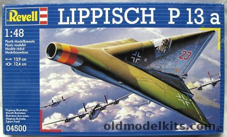
Revell even made a plastic kit of it.
Never produced although a full size wood glider version, the DM-1, was virtually complete by the war end. The Americans 'persuaded' Lippisch and his team to complete it. Transported back to the US, along with him, and was tested at the Langley full size wind tunnel where it proved to need significant modification before it exhibited the same lift characteristics as the small scale models tested in Germany.
Lippisch did know his aerodynamics, if not the problems of using a ram jet let alone a coal fired one! A very 'compact' design, well suited to be a super light weight I wondered if it could be EDF powered and keep the inlet and exhaust to scale.
Its inlet is aerodynamically sound but rather small meaning it would also have a small EDF for its size.
On the other hand the exhaust is bizarre being a narrow slot!
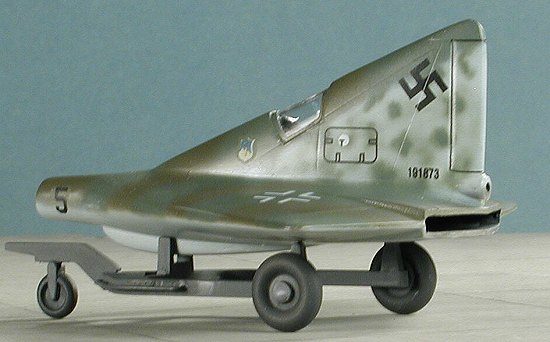
It appears the intention was to alter the slot geometry using top and bottom vanes to suit the needs of the ram jet. Yeah right!
Anyway I happen to have a 55mm brand new EDF so I did some calculations.
A 2" (51 mm) diameter inlet would match the FSA of the fan. Not ideal if really needs to be 120% FSA but still acceptable.
With a 51 mm inlet the P13a would have a span 600 mm and a length of 670 mm or 1/10 scale.
At that scale the exhaust slot would be about 17 mm high and to match the EDF's FSA would be 100 mm wide. Actually quite a bit smaller than true scale. Not a problem as it could be hidden inside the scale slot.
Of course in the P13a the duct runs from the very nose to the very tail making it a rather long thin tube but ideal for 3D printing and in LW-PLA. Then throw in a bit of lofting to go from a circular duct to a slot.
After an hour or two in Free Cad it might look something like this.

More like a vacuum cleaner hose & attachment than part of an EDF plane!
We shall but I must be daft to even consider it!
Revell even made a plastic kit of it.
Never produced although a full size wood glider version, the DM-1, was virtually complete by the war end. The Americans 'persuaded' Lippisch and his team to complete it. Transported back to the US, along with him, and was tested at the Langley full size wind tunnel where it proved to need significant modification before it exhibited the same lift characteristics as the small scale models tested in Germany.
Lippisch did know his aerodynamics, if not the problems of using a ram jet let alone a coal fired one! A very 'compact' design, well suited to be a super light weight I wondered if it could be EDF powered and keep the inlet and exhaust to scale.
Its inlet is aerodynamically sound but rather small meaning it would also have a small EDF for its size.
On the other hand the exhaust is bizarre being a narrow slot!
It appears the intention was to alter the slot geometry using top and bottom vanes to suit the needs of the ram jet. Yeah right!
Anyway I happen to have a 55mm brand new EDF so I did some calculations.
A 2" (51 mm) diameter inlet would match the FSA of the fan. Not ideal if really needs to be 120% FSA but still acceptable.
With a 51 mm inlet the P13a would have a span 600 mm and a length of 670 mm or 1/10 scale.
At that scale the exhaust slot would be about 17 mm high and to match the EDF's FSA would be 100 mm wide. Actually quite a bit smaller than true scale. Not a problem as it could be hidden inside the scale slot.
Of course in the P13a the duct runs from the very nose to the very tail making it a rather long thin tube but ideal for 3D printing and in LW-PLA. Then throw in a bit of lofting to go from a circular duct to a slot.
After an hour or two in Free Cad it might look something like this.
More like a vacuum cleaner hose & attachment than part of an EDF plane!
We shall but I must be daft to even consider it!
Thanks: Klipkopwildlife
Please Log in or Create an account to join the conversation.
- THE BLACKBIRD
-

- Offline
- Forum Master
-
Less
More
- Posts: 6368
- Thank you received: 10842
30 Dec 2022 17:05 #2
by THE BLACKBIRD
Replied by THE BLACKBIRD on topic Lippisch P13a
I just cannot see where you are going to put the coal 
Thanks: Klipkopwildlife
Please Log in or Create an account to join the conversation.
- Eric
-

- Offline
- Moderator
-

Less
More
- Posts: 13726
- Thank you received: 14467
30 Dec 2022 19:14 - 30 Dec 2022 19:29 #3
by Eric
if you are calm and collected when all about you are going berserk - you've missed something important!
Replied by Eric on topic Lippisch P13a
The fireman stands on the wing, and shovels it in through that hatch on the fin just behnd the canopy! :evil:
Perhaps it is a mis-translation, and they meant coal-oil - aka paraffin?
Perhaps it is a mis-translation, and they meant coal-oil - aka paraffin?
if you are calm and collected when all about you are going berserk - you've missed something important!
Last edit: 30 Dec 2022 19:29 by Eric. Reason: added a comment
Please Log in or Create an account to join the conversation.
- Quorneng
-
Topic Author
- Offline
- Forum Master
-
Less
More
- Posts: 9436
- Thank you received: 19043
30 Dec 2022 21:13 #4
by Quorneng
Replied by Quorneng on topic Lippisch P13a
It really was intended to be coal.
The idea was to use a 'grate' thickly coated with a layer of bonded coal dust positioned in the low speed high pressure part of the ram jet duct. It would burn for a few minutes and then you are gliding. Apparently they did achieve a 'burning grate' in a wind tunnel.
Difficult to imagine it would ever produce enough heat to expand the air enough to achieve a useful thrust. The ram jet did exist but of course used liquid fuel.
There was also supposed to be a small liquid fuel rocket motor intended to accelerate the plane to the ram jet sustain speed, 300 kph?
It really was more of a concept that practical.
Thanks: Klipkopwildlife
Please Log in or Create an account to join the conversation.
- THE BLACKBIRD
-
- Offline
- Forum Master
-
Less
More
- Posts: 6368
- Thank you received: 10842
31 Dec 2022 01:27 #5
by THE BLACKBIRD
Replied by THE BLACKBIRD on topic Lippisch P13a
I just cannot see where you are going to put the coal
Thanks: Klipkopwildlife
Please Log in or Create an account to join the conversation.
- Quorneng
-
Topic Author
- Offline
- Forum Master
-
Less
More
- Posts: 9436
- Thank you received: 19043
31 Dec 2022 15:57 #6
by Quorneng
Replied by Quorneng on topic Lippisch P13a
Just to get a feel for the size I printed out a 1/10 scale plan.

The span is 600 mm which make it about the same size as my Skyray although it would be a bit heavier as the the Skyray uses a small drone motor rather than an EDF.
The big unknown, if I do proceed, is how its very thick wing section would actually behave. My gut tells me it is likely to have high drag without any corresponding increase in lift.
Thanks: Klipkopwildlife, Flytilbroke
Please Log in or Create an account to join the conversation.
- Quorneng
-
Topic Author
- Offline
- Forum Master
-
Less
More
- Posts: 9436
- Thank you received: 19043
01 Jan 2023 23:12 #7
by Quorneng
Replied by Quorneng on topic Lippisch P13a
Slowly moving forward to create the full duct so it can be tested to see a) if it actually holds together and b) how much thrust it produces.
It is all printed in LW-PLA. The section shown in the video will be 190 mm long and weighs 6.5g.
It is one of 5 sections. 2 for the inlet and 3 for the exhaust that makes up the complete 670 mm long duct.

It is all single wall vase printed except the 90 mm scale 'nose' inlet section which has a double wall structure with an infill to ensure it does not collapse under the "less than atmospheric pressure' in the inlet likely made worse due to its restricted scale diameter.

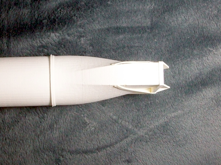
The fishtail exhaust slot.
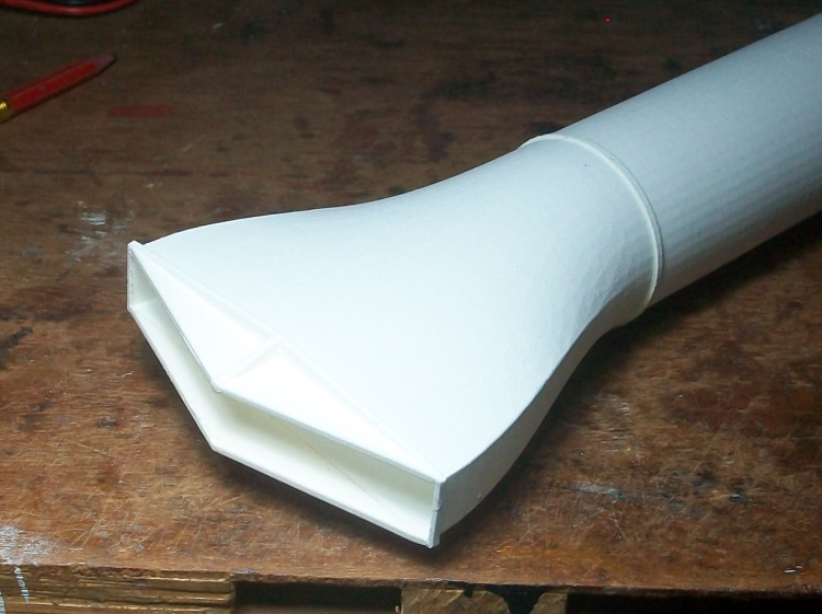
It is only half the width of the scale slot but it still matches the fan FSA.
Now all that is required is to test it.
It is all printed in LW-PLA. The section shown in the video will be 190 mm long and weighs 6.5g.
It is one of 5 sections. 2 for the inlet and 3 for the exhaust that makes up the complete 670 mm long duct.
It is all single wall vase printed except the 90 mm scale 'nose' inlet section which has a double wall structure with an infill to ensure it does not collapse under the "less than atmospheric pressure' in the inlet likely made worse due to its restricted scale diameter.
The fishtail exhaust slot.
It is only half the width of the scale slot but it still matches the fan FSA.
Now all that is required is to test it.
Thanks: Eric, Klipkopwildlife
Please Log in or Create an account to join the conversation.
- Quorneng
-
Topic Author
- Offline
- Forum Master
-
Less
More
- Posts: 9436
- Thank you received: 19043
02 Jan 2023 16:16 - 02 Jan 2023 16:18 #8
by Quorneng
Replied by Quorneng on topic Lippisch P13a
Rather as I feared the first test of the duct showed some problems.
It does indeed absorb rather a lot of thrust. At a guess about the same as the bifurcated inlet and exhaust of the Sea Hawk which does fly well enough but tt does have efficient straight wings of adequate area which the P13a does not.
Second the exhaust nozzle vibrates! You can hear the 'drone' on this video.
The inlet part of the duct by itself does not to create too much loss and anyway its effectiveness should improve significantly with forward velocity where as less so for the exhaust duct. It looks like it is the long exhaust that need attention.
Last edit: 02 Jan 2023 16:18 by Quorneng.
Thanks: Klipkopwildlife
Please Log in or Create an account to join the conversation.
- Quorneng
-
Topic Author
- Offline
- Forum Master
-
Less
More
- Posts: 9436
- Thank you received: 19043
03 Jan 2023 21:32 #9
by Quorneng
Replied by Quorneng on topic Lippisch P13a
Some reprinting of the exhaust duct.
The duct is 1mm larger diameter to match the inner diameter of the EDF casing which is 56 mm rather than the 55 mm of the fan. Thee is a 1mm tip clearance to allow the fan to 'grow' at high speed.
The larger duct suggest the nozzle slot can be larger now 19 x 100 mm rather than the previous 15 mm.
The actual loft from the circle to the slot is also changed to keep a better constant area as it does so. The first loft looked to me like it restricted the duct area during the shape change.
The external faces of the new slot also have better stiffening ribs to prevent the fluttering drone.
Revised slot on the left.
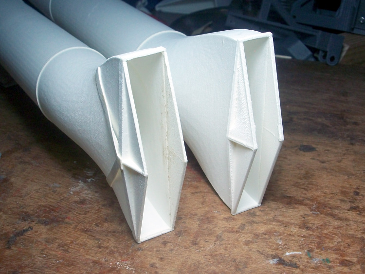
A quick test has certainly stopped the fluttering drone and it does 'blow the door shut' a bit better than before but definitely still not as fast as the bare EDF.
Now probably enough thrust to fly the Lippisch P13a but still a couple of things I would like to try before starting any airframe building. .
The duct is 1mm larger diameter to match the inner diameter of the EDF casing which is 56 mm rather than the 55 mm of the fan. Thee is a 1mm tip clearance to allow the fan to 'grow' at high speed.
The larger duct suggest the nozzle slot can be larger now 19 x 100 mm rather than the previous 15 mm.
The actual loft from the circle to the slot is also changed to keep a better constant area as it does so. The first loft looked to me like it restricted the duct area during the shape change.
The external faces of the new slot also have better stiffening ribs to prevent the fluttering drone.
Revised slot on the left.
A quick test has certainly stopped the fluttering drone and it does 'blow the door shut' a bit better than before but definitely still not as fast as the bare EDF.
Now probably enough thrust to fly the Lippisch P13a but still a couple of things I would like to try before starting any airframe building. .
Thanks: Eric, Klipkopwildlife
Please Log in or Create an account to join the conversation.
- Klipkopwildlife
-

- Offline
- Administrator
-

- I'm supposed to be retired!
04 Jan 2023 07:54 #10
by Klipkopwildlife
Do it now, you may never get another chance
Replied by Klipkopwildlife on topic Lippisch P13a
Under the premise of 'if it looks right it generally is right' I think you're on a hiding to bugger all squared.[badass]
Do it now, you may never get another chance
Thanks: Eric
Please Log in or Create an account to join the conversation.
- Quorneng
-
Topic Author
- Offline
- Forum Master
-
Less
More
- Posts: 9436
- Thank you received: 19043
06 Jan 2023 20:47 #11
by Quorneng
Replied by Quorneng on topic Lippisch P13a
Having satisfied my self with the thrust level from the improved duct. It now has a ruling diameter of the EDF body at 56 mm diameter rather than the 55 mm of the fan ad well as a more bulbous change from a circle to the slot which has also been slightly increased in height.
To actually build the airframe I need a decent 'line' drawing rather than the 'fuzzy' lines in the 3 view which become impossibly wide when they are blown up by 6 times.

Each line is carefully redrawn and the excess fuzz removed virtually a pixel at a time. All the lines are now one pixel wide and black.

Slow and tedious it is not a process I would recommend to anyone.
A symmetrical, thick and blunt nosed wing section. Wow!

To actually build the airframe I need a decent 'line' drawing rather than the 'fuzzy' lines in the 3 view which become impossibly wide when they are blown up by 6 times.
Each line is carefully redrawn and the excess fuzz removed virtually a pixel at a time. All the lines are now one pixel wide and black.
Slow and tedious it is not a process I would recommend to anyone.
A symmetrical, thick and blunt nosed wing section. Wow!
Thanks: Klipkopwildlife, Flytilbroke, THE BLACKBIRD
Please Log in or Create an account to join the conversation.
- Eric
-
- Offline
- Moderator
-
Less
More
- Posts: 13726
- Thank you received: 14467
06 Jan 2023 23:41 #12
by Eric
if you are calm and collected when all about you are going berserk - you've missed something important!
Replied by Eric on topic Lippisch P13a
Don't forget that this was in the early days of monoplanes, when the general concensus was that thin wings would be too weak and bendy!
if you are calm and collected when all about you are going berserk - you've missed something important!
Thanks: Klipkopwildlife
Please Log in or Create an account to join the conversation.
- Klipkopwildlife
-
- Offline
- Administrator
-
- I'm supposed to be retired!
07 Jan 2023 07:58 - 07 Jan 2023 08:01 #13
by Klipkopwildlife
Do it now, you may never get another chance
Replied by Klipkopwildlife on topic Lippisch P13a
R.J. Mitchell got it right, Sydney Cam never did!

Do it now, you may never get another chance
Last edit: 07 Jan 2023 08:01 by Klipkopwildlife.
Please Log in or Create an account to join the conversation.
- Quorneng
-
Topic Author
- Offline
- Forum Master
-
Less
More
- Posts: 9436
- Thank you received: 19043
10 Jan 2023 20:50 #14
by Quorneng
Replied by Quorneng on topic Lippisch P13a
Made a start on the P13a.
The fuselage half shell but it includes 1/3 of the wing..
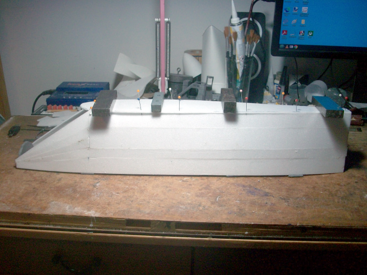
All 3mm Depron
Its thick wing section.
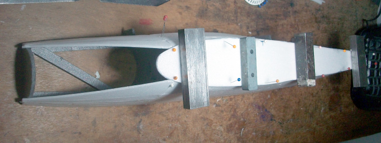
That's not the root but the section at 1/3 span!
A bit more skin to go on and then the fun really begins - getting the full duct including the EDF to fit exactly 'half sunk' into all the formers.
The fuselage half shell but it includes 1/3 of the wing..
All 3mm Depron
Its thick wing section.
That's not the root but the section at 1/3 span!
A bit more skin to go on and then the fun really begins - getting the full duct including the EDF to fit exactly 'half sunk' into all the formers.
Thanks: Klipkopwildlife
Please Log in or Create an account to join the conversation.
- Quorneng
-
Topic Author
- Offline
- Forum Master
-
Less
More
- Posts: 9436
- Thank you received: 19043
11 Jan 2023 15:47 #15
by Quorneng
Replied by Quorneng on topic Lippisch P13a
As I expected the new toilet does not fit!
The existing toilet had a right angle bend on the outlet so the soil pipe went out the side wall.
The new outlet outlet is is about 3 cm different in height and position. Far more than the soil pipi joints can handle so a flexible right angle bend has been ordered.
The result is the toilet fitting is "stood down" for two days so I can get on with the Lippisch!

With the fuselage half shell more or less complete the 'first fit' of the rear potion of the duct.

Nearly there just a little bit more tweaking to ensure it is exactly half way in.
The exhaust slot.

It is only half the scale width but the outer dummy area will be made up in thin Depron to look similar.
So far so good but it is only 1/4 of the airframe.
The existing toilet had a right angle bend on the outlet so the soil pipe went out the side wall.
The new outlet outlet is is about 3 cm different in height and position. Far more than the soil pipi joints can handle so a flexible right angle bend has been ordered.
The result is the toilet fitting is "stood down" for two days so I can get on with the Lippisch!
With the fuselage half shell more or less complete the 'first fit' of the rear potion of the duct.
Nearly there just a little bit more tweaking to ensure it is exactly half way in.
The exhaust slot.
It is only half the scale width but the outer dummy area will be made up in thin Depron to look similar.
So far so good but it is only 1/4 of the airframe.
Thanks: Klipkopwildlife, Flytilbroke, THE BLACKBIRD
Please Log in or Create an account to join the conversation.
Time to create page: 0.848 seconds