
- Posts: 9436
- Thank you received: 19043
Building a foam wing.
- Quorneng
-
 Topic Author
- Offline
- Forum Master
-

Less
More
16 Oct 2012 18:52 #1
by Quorneng
Building a foam wing. was created by Quorneng
Why foam?
In most smaller models very little of the material used in its construction is actually stressed to anything like its ultimate load so overall the structure is heavier than it need be, however if the components are reduced in size to match their loads they become too weak to stand being handled.
Foam is much less dense than balsa so even 'feather weight' lightly loaded components can still be rigid enough to be handled.
On this basis I decided to try building up a wing out of thin Depron sheet in the same way as a conventional balsa structure and only using balsa for the highest stressed element.
As Depron is not as rigid a balsa the intent was to use a very substantial box spar with light Depron 'fairings' fore and aft to create the wing section.
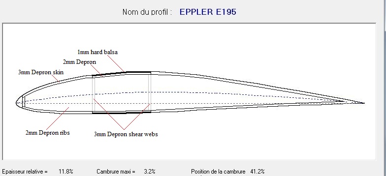
To save weight even the box spar is a built up Depron structure with just a hard balsa 1mm 'veneer' on its top and bottom surfaces, like this.
First a small 'test' wing section to determine if
a) It was possible to build like this
b) How strong and stiff it would be.
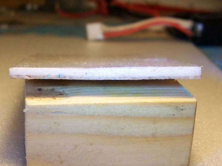
The top and bottom of the box spar is made up of 1mm balsa backed by 2mm Depron.
Depron ribs glued to the box spar bottom surface.

The sheer webs being added to create the 'box'.

The wing skin (3mm Depron) fore and aft of the spar is the same thickness as the box spar top and bottom flanges so the ribs are 'continuous' and have no cut outs.
As Depron is so light there is very little weight penalty and considerable stiffness added by having a relatively thick full sheet covering. It also helps to maintain an accurate wing section.
The final result is very impressive.
4 inches of a 10" chord wing 1.25" deep weighs just over 1/3oz and is outstandingly rigid.

On this basis the intended 80" span tapered wing should weigh no more than 7oz.
Finding out if this proves to be the case is to me half the fun although it is likely to be a time con summing process.
In most smaller models very little of the material used in its construction is actually stressed to anything like its ultimate load so overall the structure is heavier than it need be, however if the components are reduced in size to match their loads they become too weak to stand being handled.
Foam is much less dense than balsa so even 'feather weight' lightly loaded components can still be rigid enough to be handled.
On this basis I decided to try building up a wing out of thin Depron sheet in the same way as a conventional balsa structure and only using balsa for the highest stressed element.
As Depron is not as rigid a balsa the intent was to use a very substantial box spar with light Depron 'fairings' fore and aft to create the wing section.
To save weight even the box spar is a built up Depron structure with just a hard balsa 1mm 'veneer' on its top and bottom surfaces, like this.
First a small 'test' wing section to determine if
a) It was possible to build like this
b) How strong and stiff it would be.
The top and bottom of the box spar is made up of 1mm balsa backed by 2mm Depron.
Depron ribs glued to the box spar bottom surface.
The sheer webs being added to create the 'box'.
The wing skin (3mm Depron) fore and aft of the spar is the same thickness as the box spar top and bottom flanges so the ribs are 'continuous' and have no cut outs.
As Depron is so light there is very little weight penalty and considerable stiffness added by having a relatively thick full sheet covering. It also helps to maintain an accurate wing section.
The final result is very impressive.
4 inches of a 10" chord wing 1.25" deep weighs just over 1/3oz and is outstandingly rigid.
On this basis the intended 80" span tapered wing should weigh no more than 7oz.
Finding out if this proves to be the case is to me half the fun although it is likely to be a time con summing process.
Thanks: Sarah-Jane Smith
Please Log in or Create an account to join the conversation.
- Grumpy42
- User
-

Less
More
- Thank you received: 0
16 Oct 2012 19:45 #2
by Grumpy42
Replied by Grumpy42 on topic Re: Building a foam wing.
That's very interesting - I'm just wondering how the box spar will handle torsional and lateral loads at the longer length. A tapered wing will reduce those problems but then you have the possibility of building in tip stall - I'll watch with interest.
Please Log in or Create an account to join the conversation.
- The Beard
-

- Offline
- Forum Master
-
Less
More
- Posts: 6913
- Thank you received: 2167
16 Oct 2012 21:47 #3
by The Beard
Replied by The Beard on topic Re: Building a foam wing.
Yes this is something that fascinates me look forward to the procedure.
Please Log in or Create an account to join the conversation.
- Powerless Poly
-

- Offline
- Banned
-

Less
More
- Posts: 16
- Thank you received: 9
16 Oct 2012 22:15 #4
by Powerless Poly
Replied by Powerless Poly on topic Re: Building a foam wing.
I'm about to build a foam veneered 56 inch span wing & I had the idea of cutting the core & drilling loads of holes in it before veneering. .... This would almost achieve the same thing as this method but a bit more like a single layer honeycomb.
I'll watch the outcome of your experiments first & pick your brains.
Pol.
I'll watch the outcome of your experiments first & pick your brains.
Pol.
Please Log in or Create an account to join the conversation.
- Eric
-

- Offline
- Moderator
-

Less
More
- Posts: 13729
- Thank you received: 14474
16 Oct 2012 22:42 #5
by Eric
if you are calm and collected when all about you are going berserk - you've missed something important!
Replied by Eric on topic Re: Building a foam wing.
Something similar was tried a while back, Pol, a regular foam/veneer wing was cut and covered, then fed through a band-saw to make it into ribs, which were then assembled into a much larger span wing, built up in the regular way with spruce spars, balsa le and te, etc. It worked, but wasn't a great deal lighter than a simple balsa built up wing, but with the added complication and faffing about!
if you are calm and collected when all about you are going berserk - you've missed something important!
Please Log in or Create an account to join the conversation.
- Quorneng
-
Topic Author
- Offline
- Forum Master
-
Less
More
- Posts: 9436
- Thank you received: 19043
17 Oct 2012 01:11 #6
by Quorneng
Replied by Quorneng on topic Re: Building a foam wing.
The weather is rotten so I will press on.
First the box spar top and bottom sections. 1mm hard balsa backed by 2mm Depron. The box tapers in width from 1.5" at the root to 1/4" at the tip.
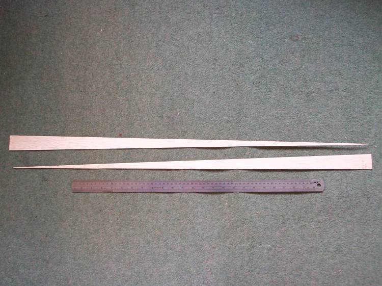
To make life a bit easier to build a Clarke Y section is used, 12% at the root giving a thickness of 1.25" reducing to a 9% section at the tip giving a thickness of 0.375".
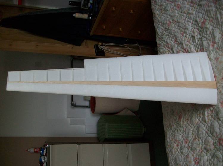
The construction sequence was slightly different to the test wing in that front and rear sections of the underside skin were glued to the lower box spar section creating the complete wing lower skin.
Before the 19 Depron ribs were glued on the forward part of the skin was 'curved' up wards to match the rib profile.

Due to the extreme taper the 'box' construction actually stops before the tip and in the last 4 ribs the spar continues as a 'I' beam.
Note the very trailing edge of the skin has been sanded down to a fine edge.
With the top of the box spar and nose skin added the wing is rigid.
At this point before I started on the other side I wanted an idea of how strong it was.
Even in its incomplete state (it weighed just under 2oz) it easily carried a 6oz tip load with just 4" of the root supported.
By my 'rule of thumb' this would be a bending stress equivalent to pulling 4g with a 12oz fuselage.
To give good access to the centre wing skin joint the LH wing was actually built onto the RH half.
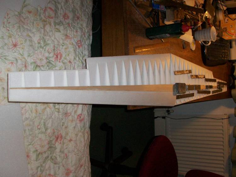
So far so good. Strong enough and extremely light but before the last part of the skin can be added the aileron servos with their long extension leads have to go in.
First the box spar top and bottom sections. 1mm hard balsa backed by 2mm Depron. The box tapers in width from 1.5" at the root to 1/4" at the tip.
To make life a bit easier to build a Clarke Y section is used, 12% at the root giving a thickness of 1.25" reducing to a 9% section at the tip giving a thickness of 0.375".
The construction sequence was slightly different to the test wing in that front and rear sections of the underside skin were glued to the lower box spar section creating the complete wing lower skin.
Before the 19 Depron ribs were glued on the forward part of the skin was 'curved' up wards to match the rib profile.
Due to the extreme taper the 'box' construction actually stops before the tip and in the last 4 ribs the spar continues as a 'I' beam.
Note the very trailing edge of the skin has been sanded down to a fine edge.
With the top of the box spar and nose skin added the wing is rigid.
At this point before I started on the other side I wanted an idea of how strong it was.
Even in its incomplete state (it weighed just under 2oz) it easily carried a 6oz tip load with just 4" of the root supported.
Attachment LoadTest.jpg not found
By my 'rule of thumb' this would be a bending stress equivalent to pulling 4g with a 12oz fuselage.
To give good access to the centre wing skin joint the LH wing was actually built onto the RH half.
So far so good. Strong enough and extremely light but before the last part of the skin can be added the aileron servos with their long extension leads have to go in.
Thanks: Klipkopwildlife, Sarah-Jane Smith
Please Log in or Create an account to join the conversation.
- Quorneng
-
Topic Author
- Offline
- Forum Master
-
Less
More
- Posts: 9436
- Thank you received: 19043
17 Oct 2012 18:07 - 17 Oct 2012 18:16 #7
by Quorneng
Replied by Quorneng on topic Re: Building a foam wing.
This is a super lightweight wing so of course it has super lightweight servos - 3.7g ones!
They would normally be considered totally inadequate for anything but the lightest foamy but are they?
My own view is that most servos are grossly over powered partly because of past custom and practise and partly to over come friction in inefficient linkages and hinges.
In light aircraft the actual control forces required to overcome the aerodynamic loads from conventional control surfaces are actually quite small , in the order of 1/100 the weight of the plane.
This wing will be used on a plane that weighs 650g so the 500g available at the outer servo hole horn should be sufficient!
The tiny servo 'built in' just behind the box spar at the aileron mid point.

To spread the forces generated by the servo it is glued directly to the spar rear face, the rib and the lower skin.
Just the tip of the servo horn protrudes from the underside.

At such light weights even the servo cable become significant so 32AWG is used with just one connector per wing.

I have to make an admission the wing is not 80" but 78. The balsa in the box spar was limited to 36" and it has 3" raked wing tips!
And the aileorn hinge? just a strip sticky tape! Very light, flexible and provides a smooth 'sealed' hinge.
The completed wing was put through another 'wing tip' load test this time with a centre load of 18oz.

The camera was on a tripod which shows a deflection of about 1.5".
This was of course not its ultimate load but still represents the equivalent of pulling 4g (a loop) with its 17oz fuselage.
Nevertheless in construction terms it achieved it objective, indeed it exceeded it, as the complete wing including servos weighs not 8oz but 5.6oz!
At 23oz all up this plane certainly demonstrates what a real 'floater' is like.

And with a static thrust well in excess of its weight it can "climb like a monkey" to quote von Richthofen describing the Fokker Triplane!
They would normally be considered totally inadequate for anything but the lightest foamy but are they?
My own view is that most servos are grossly over powered partly because of past custom and practise and partly to over come friction in inefficient linkages and hinges.
In light aircraft the actual control forces required to overcome the aerodynamic loads from conventional control surfaces are actually quite small , in the order of 1/100 the weight of the plane.
This wing will be used on a plane that weighs 650g so the 500g available at the outer servo hole horn should be sufficient!
The tiny servo 'built in' just behind the box spar at the aileron mid point.
To spread the forces generated by the servo it is glued directly to the spar rear face, the rib and the lower skin.
Just the tip of the servo horn protrudes from the underside.
At such light weights even the servo cable become significant so 32AWG is used with just one connector per wing.
I have to make an admission the wing is not 80" but 78. The balsa in the box spar was limited to 36" and it has 3" raked wing tips!
And the aileorn hinge? just a strip sticky tape! Very light, flexible and provides a smooth 'sealed' hinge.
The completed wing was put through another 'wing tip' load test this time with a centre load of 18oz.
The camera was on a tripod which shows a deflection of about 1.5".
This was of course not its ultimate load but still represents the equivalent of pulling 4g (a loop) with its 17oz fuselage.
Nevertheless in construction terms it achieved it objective, indeed it exceeded it, as the complete wing including servos weighs not 8oz but 5.6oz!
At 23oz all up this plane certainly demonstrates what a real 'floater' is like.
And with a static thrust well in excess of its weight it can "climb like a monkey" to quote von Richthofen describing the Fokker Triplane!
Last edit: 17 Oct 2012 18:16 by Quorneng.
Thanks: Klipkopwildlife, Sarah-Jane Smith
Please Log in or Create an account to join the conversation.
Time to create page: 0.783 seconds