
- Posts: 9436
- Thank you received: 19043
North American XB70 Valkyrie
- Quorneng
-
 Topic Author
- Offline
- Forum Master
-

Less
More
14 Feb 2014 19:11 - 14 Feb 2014 19:13 #1
by Quorneng
North American XB70 Valkyrie was created by Quorneng
The success of the 6 nozzle test duct has persuaded me to set about building an XB70.
Not in any great hurry as I want to finish and fly the Concorde first.
It will be 40" span and 72" long, hand launch and belly land.
I have not yet decided whether to make the canards moveable or fixed.
I have spent many hours tidying up this side view and fuselage sections.

It shows the visor raised and the nozzles restricted down to an appropriate area for the 70mm fan.
The top surface of the EDF duct will be the underside of the wing so it follows the wing will have to built first.
This poses the same problem I had with my Concorde of how to actually install the EDF with its oddly shaped inlet and outlet ducts.
The solution I am proposing is to built the first 1/3 of the duct complete with the fan as a 'stand alone' unit that can then be fixed into the underside of the wing. The remaining 2/3 of the duct will be a simple 'open topped' box glued to the underside of the wing.
The first 1/3 of the duct ("the nose duct") will look something like this.

The bell mouth of the EDF will be cut off.
It will be built in two parts, inlet and outlet, that will be joined on the fan housing.
This duct will be built first.
Oh! I nearly forgot. It will be made of Depron!
Not in any great hurry as I want to finish and fly the Concorde first.
It will be 40" span and 72" long, hand launch and belly land.
I have not yet decided whether to make the canards moveable or fixed.
I have spent many hours tidying up this side view and fuselage sections.
It shows the visor raised and the nozzles restricted down to an appropriate area for the 70mm fan.
The top surface of the EDF duct will be the underside of the wing so it follows the wing will have to built first.
This poses the same problem I had with my Concorde of how to actually install the EDF with its oddly shaped inlet and outlet ducts.
The solution I am proposing is to built the first 1/3 of the duct complete with the fan as a 'stand alone' unit that can then be fixed into the underside of the wing. The remaining 2/3 of the duct will be a simple 'open topped' box glued to the underside of the wing.
The first 1/3 of the duct ("the nose duct") will look something like this.
The bell mouth of the EDF will be cut off.
It will be built in two parts, inlet and outlet, that will be joined on the fan housing.
This duct will be built first.
Oh! I nearly forgot. It will be made of Depron!
Last edit: 14 Feb 2014 19:13 by Quorneng.
Thanks: Eric, Klipkopwildlife, blue123, Sarah-Jane Smith, old fart
Please Log in or Create an account to join the conversation.
- Ex-Member
- User
-

Less
More
- Thank you received: 0
14 Feb 2014 19:21 #2
by Ex-Member
Replied by Ex-Member on topic North American XB70 Valkyrie
i was wondering how long it would be before the builds started. 
Please Log in or Create an account to join the conversation.
- Ex-Member
- User
-
Less
More
- Thank you received: 0
14 Feb 2014 22:43 #3
by Ex-Member
Me too! :lol: :lol:
I wonder how many other builds 'won't' be started this year
Replied by Ex-Member on topic North American XB70 Valkyrie
Tony B wrote: i was wondering how long it would be before the builds started.
Me too! :lol: :lol:
I wonder how many other builds 'won't' be started this year
Please Log in or Create an account to join the conversation.
- Quorneng
-
Topic Author
- Offline
- Forum Master
-
Less
More
- Posts: 9436
- Thank you received: 19043
16 Feb 2014 18:51 - 16 Feb 2014 18:57 #4
by Quorneng
Replied by Quorneng on topic North American XB70 Valkyrie
A modest start. The rear section of the 'Nose Duct'.
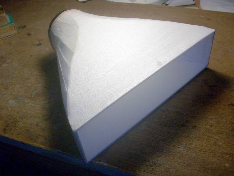
I fear this duct is going to break all the 'rules' of EDFs about the ratio of the duct area to the fan area.
The 70mm EDF has a Fan Swept Area (FSA) of 3233 sqmm.
The area of the outlet of this portion of the duct is 12768 sqmm (3.9 times the FSA :woohoo: )
The duct then gets even bigger to 18900 sqmm (5.8 x FSA) then reduces slightly to 13500 sqmm (4.2 x FSA). The six 26mm diam nozzles will have an exit area of 3126 sqmm or 97% of the FSA.
But what effect will these big area changes have on the static thrust?
In theory what should happen is the air simply slows down in the larger area portions of the duct and then speeds up again to virtually the same as the fan exit velocity as it is squeezed through the nozzles.
The previous slightly smaller six nozzle duct delivered 27oz thrust. With the same EDF and battery will it be more or less with this one?
Last edit: 16 Feb 2014 18:57 by Quorneng.
Thanks: Eric, Klipkopwildlife, blue123, Sarah-Jane Smith, old fart
Please Log in or Create an account to join the conversation.
- Quorneng
-
Topic Author
- Offline
- Forum Master
-
Less
More
- Posts: 9436
- Thank you received: 19043
17 Feb 2014 23:56 #5
by Quorneng
Replied by Quorneng on topic North American XB70 Valkyrie
The 70mm EDF mounted on the rear section of the nose duct.
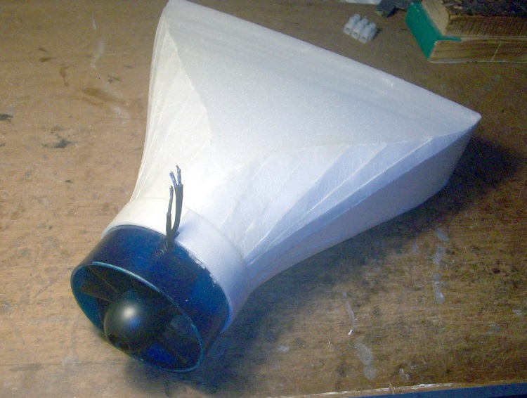
The front section of the duct showing the Valkyrie trade mark inlet.

It is huge!

It has an area of 8024 sqmm which is over twice the fan area.
This should mean good static thrust but it will create too much drag to fly particularly fast.
Of course on the full size this shape was designed to ensure the supersonic shock wave never entered the engines rather than have low drag at slower speeds.
The front section of the duct showing the Valkyrie trade mark inlet.
It is huge!
It has an area of 8024 sqmm which is over twice the fan area.
This should mean good static thrust but it will create too much drag to fly particularly fast.
Of course on the full size this shape was designed to ensure the supersonic shock wave never entered the engines rather than have low drag at slower speeds.
Thanks: Eric, Klipkopwildlife, Ex-Member, blue123, Sarah-Jane Smith, old fart
Please Log in or Create an account to join the conversation.
- Quorneng
-
Topic Author
- Offline
- Forum Master
-
Less
More
- Posts: 9436
- Thank you received: 19043
19 Feb 2014 15:03 #6
by Quorneng
Replied by Quorneng on topic North American XB70 Valkyrie
The 'nose duct' is now complete.

That is a 2200mAh 3s along side for comparison.
Quite a complex upper surface as the fan housing is bigger than the duct is deep. No problem as it has the fuselage above it.
The under surface is completely flat.

Now I have just got to build the full wing in order to complete the rest of the duct so I can find out how much thrust is does (or does not!) give.
That is a 2200mAh 3s along side for comparison.
Quite a complex upper surface as the fan housing is bigger than the duct is deep. No problem as it has the fuselage above it.
The under surface is completely flat.
Now I have just got to build the full wing in order to complete the rest of the duct so I can find out how much thrust is does (or does not!) give.
Thanks: Eric, Klipkopwildlife, blue123, Sarah-Jane Smith, old fart
Please Log in or Create an account to join the conversation.
- Eric
-

- Offline
- Moderator
-

Less
More
- Posts: 13726
- Thank you received: 14470
19 Feb 2014 16:12 #7
by Eric
if you are calm and collected when all about you are going berserk - you've missed something important!
Replied by Eric on topic North American XB70 Valkyrie
All this time and effort for a model that you are not going to build!
if you are calm and collected when all about you are going berserk - you've missed something important!
Please Log in or Create an account to join the conversation.
- Quorneng
-
Topic Author
- Offline
- Forum Master
-
Less
More
- Posts: 9436
- Thank you received: 19043
19 Feb 2014 19:01 #8
by Quorneng
Replied by Quorneng on topic North American XB70 Valkyrie
To be fair in post #1 I did say
It was the smaller 'test' duct that was not going to turn into a plane.The success of the 6 nozzle test duct has persuaded me to set about building an XB70.
Thanks: Eric
Please Log in or Create an account to join the conversation.
- Quorneng
-
Topic Author
- Offline
- Forum Master
-
Less
More
- Posts: 9436
- Thank you received: 19043
19 Feb 2014 23:58 #9
by Quorneng
Replied by Quorneng on topic North American XB70 Valkyrie
The XB70 wing.

The quite substantial bit I have built already is outlined in red and looks tiny! :ohmy:
The quite substantial bit I have built already is outlined in red and looks tiny! :ohmy:
Thanks: Klipkopwildlife, Sarah-Jane Smith, old fart
Please Log in or Create an account to join the conversation.
- Quorneng
-
Topic Author
- Offline
- Forum Master
-
Less
More
- Posts: 9436
- Thank you received: 19043
25 Feb 2014 20:58 - 25 Feb 2014 21:00 #10
by Quorneng
Replied by Quorneng on topic North American XB70 Valkyrie
I need to built enough to be able to complete duct so I can check the thrust. If it still gives close to 27oz as with the smaller version then the build can continue.
The top of most of the duct is the underside of the wing so it has to be built all at the same time.

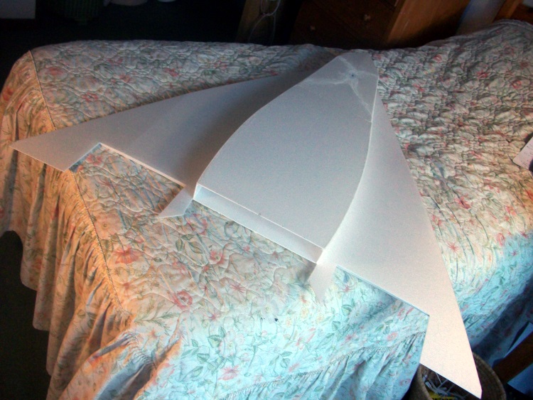
Next comes the nozzles.

A bit of a trial and error process to arrive at exactly the right square end (45.5 x45.5mm ) and reducing to 28mm ID (the size of a Humbrol tinlet!)
The six nozzles.

They have exactly the same area as the previous duct.
The wing has a lot of shear webs.

The wing will remain pretty floppy until the top skin goes on. It is after all a true stressed skin structure.
Note the huge area of the scale elevators/ailerons.
The top of most of the duct is the underside of the wing so it has to be built all at the same time.
Next comes the nozzles.
A bit of a trial and error process to arrive at exactly the right square end (45.5 x45.5mm ) and reducing to 28mm ID (the size of a Humbrol tinlet!)
The six nozzles.
They have exactly the same area as the previous duct.
The wing has a lot of shear webs.
The wing will remain pretty floppy until the top skin goes on. It is after all a true stressed skin structure.
Note the huge area of the scale elevators/ailerons.
Last edit: 25 Feb 2014 21:00 by Quorneng.
Thanks: Eric, Klipkopwildlife, Ex-Member, blue123, Sarah-Jane Smith, old fart
Please Log in or Create an account to join the conversation.
- Quorneng
-
Topic Author
- Offline
- Forum Master
-
Less
More
- Posts: 9436
- Thank you received: 19043
26 Feb 2014 20:28 - 26 Feb 2014 20:30 #11
by Quorneng
Replied by Quorneng on topic North American XB70 Valkyrie
Now ready to test the EDF and duct.
But then I had a bit of an ooops! moment as the power was very gradually built up.
Pressure ducts tend to circular. A non circular duct on the other hand tends to be forced into circular shape. The fan tried to blow up the duct like a balloon! :woohoo:
After a bit of thinking I have now divided the duct down the middle so it is now made up of two side by side each feeding 3 nozzles. As each duct now only half the width it will resist internal pressure much better - I hope!
The inserted divider.
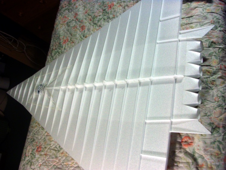
With the camera looking through an inner nozzle the divider is visible.
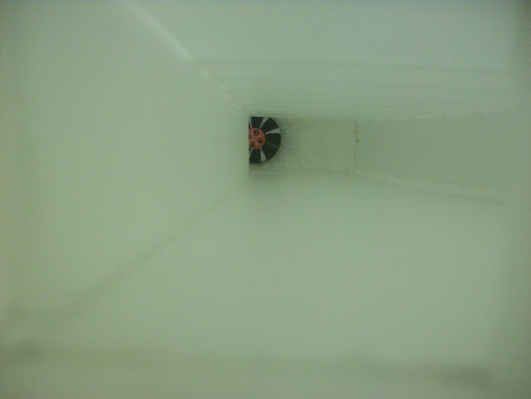
I dare not use full power until the glue is really dry but it no longer distorts at 3/4 power (35A).
But then I had a bit of an ooops! moment as the power was very gradually built up.
Pressure ducts tend to circular. A non circular duct on the other hand tends to be forced into circular shape. The fan tried to blow up the duct like a balloon! :woohoo:
After a bit of thinking I have now divided the duct down the middle so it is now made up of two side by side each feeding 3 nozzles. As each duct now only half the width it will resist internal pressure much better - I hope!
The inserted divider.
With the camera looking through an inner nozzle the divider is visible.
I dare not use full power until the glue is really dry but it no longer distorts at 3/4 power (35A).
Last edit: 26 Feb 2014 20:30 by Quorneng.
Thanks: Eric, Klipkopwildlife, Ex-Member, blue123, Sarah-Jane Smith, old fart
Please Log in or Create an account to join the conversation.
- Quorneng
-
Topic Author
- Offline
- Forum Master
-
Less
More
- Posts: 9436
- Thank you received: 19043
27 Feb 2014 17:36 #12
by Quorneng
Replied by Quorneng on topic North American XB70 Valkyrie
Managed a full power (but not fully charged battery) run this morning showing 45.1A, 448W at 9.8V.
The underside of each half of the duct does bow slightly but nothing serious.
It produces just under 27oz thrust. A little bit less than before but I suppose this is to be expected as with its scale inlet the whole duct is nearly 50% longer than the 'test' one.
Next is to fit four servos. One for each elevator and aileron. Then the top wing skin can go on.
As this stage the best guess at the final weight is - a bit less than the static thrust!
Thanks: Eric, blue123, Sarah-Jane Smith
Please Log in or Create an account to join the conversation.
- Quorneng
-
Topic Author
- Offline
- Forum Master
-
Less
More
- Posts: 9436
- Thank you received: 19043
04 Mar 2014 00:10 #13
by Quorneng
Replied by Quorneng on topic North American XB70 Valkyrie
With the arrival of some 32 AWG servo wire the 4 servos go in, elevators inboard.

So how come the elevator pair are symmetrically mounted yet electrically connected?
So how come the elevator pair are symmetrically mounted yet electrically connected?
Thanks: Klipkopwildlife, blue123, Sarah-Jane Smith
Please Log in or Create an account to join the conversation.
- Quorneng
-
Topic Author
- Offline
- Forum Master
-
Less
More
- Posts: 9436
- Thank you received: 19043
04 Mar 2014 23:00 - 04 Mar 2014 23:01 #14
by Quorneng
Replied by Quorneng on topic North American XB70 Valkyrie
Today the top skin went on.

A truly huge length of glue line required but nevertheless it went on quite well.
The tips have been set at 4 degrees positive dihedral which was the preferred position for slow speed low altitude flight.
Quite a bit of finishing still required on the wing.
Will have to start thinking about the fuselage although it only has to hold the radio and battery.
Last edit: 04 Mar 2014 23:01 by Quorneng.
Thanks: Eric, Klipkopwildlife, blue123, Sarah-Jane Smith, old fart
Please Log in or Create an account to join the conversation.
- Quorneng
-
Topic Author
- Offline
- Forum Master
-
Less
More
- Posts: 9436
- Thank you received: 19043
06 Mar 2014 11:48 #15
by Quorneng
Replied by Quorneng on topic North American XB70 Valkyrie
The fuselage formers for the nose ahead of the wing.

This will be built as a half shell oner the plan in 3mm Depron. Although much of the rest of the structure only uses 2mm Depron I will use the thicker material on the fuselage as it has quite a small cross section.
The rear part of the fuselage will be built as one piece 'insitu' on the wing.
I am still undecided whether to make the nose removable. It would be lighter and stronger to have it fixed but I am not sure it will fit in my car! :woohoo:
Thanks: Klipkopwildlife, Ex-Member, blue123, Sarah-Jane Smith
Please Log in or Create an account to join the conversation.
Time to create page: 0.991 seconds