
- Posts: 9436
- Thank you received: 19043
Some more lofting
- Quorneng
-
 Topic Author
- Offline
- Forum Master
-

Less
More
07 Nov 2022 10:23 #1
by Quorneng
Some more lofting was created by Quorneng
Just out of curiosity I wondered if it was possible to "loft" a complete wing.
In principle starting with a root wing section it should be possible by using some intermediate sections to loft an oval wing (Spitfire?) including a smooth change of wing section root to tip.
To be realistic I decided to test the principle with a simple straight taper wing.
First a root section.

It actually the same as the Depron Seagull.
Then a reduced size tip section.

Finally the two sketches lofted 400 mm apart.

Of course it is taller than the maximum print height but it can be 'submerged' 200 mm into the bed & printed.
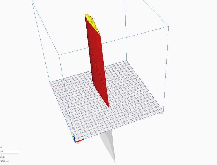
Then turned over and other half completed.
According to CURA both halves of the 400 mm wing half would weigh 41g and take 6hr 45 min to print.
My intention is to use just a stressed skin, no spar, but with a "gyroid" infill.
This is the Lh wing but the clever trick is the Rh one can be created by simply moving the outer sketch from 400 mm to - 400 mm!
With two more wing section sketches an 'outer' wing panel, with a cut out for the aileron, will give a 600 mm half wing.
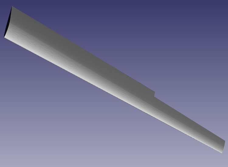
Total print for the 3 sections of the half wing would be 8hrs 31 min :woohoo: but I am printing at a fairly modest 50 mm/sec due to the age of my Anet A8!
As expected such a wing in LW-PLA would be about twice as heavy as if 2mm Depron sheet was used!
I might print just one section to see how it turns out
In principle starting with a root wing section it should be possible by using some intermediate sections to loft an oval wing (Spitfire?) including a smooth change of wing section root to tip.
To be realistic I decided to test the principle with a simple straight taper wing.
First a root section.
It actually the same as the Depron Seagull.
Then a reduced size tip section.
Finally the two sketches lofted 400 mm apart.
Of course it is taller than the maximum print height but it can be 'submerged' 200 mm into the bed & printed.
Then turned over and other half completed.
According to CURA both halves of the 400 mm wing half would weigh 41g and take 6hr 45 min to print.
My intention is to use just a stressed skin, no spar, but with a "gyroid" infill.
This is the Lh wing but the clever trick is the Rh one can be created by simply moving the outer sketch from 400 mm to - 400 mm!
With two more wing section sketches an 'outer' wing panel, with a cut out for the aileron, will give a 600 mm half wing.
Total print for the 3 sections of the half wing would be 8hrs 31 min :woohoo: but I am printing at a fairly modest 50 mm/sec due to the age of my Anet A8!
As expected such a wing in LW-PLA would be about twice as heavy as if 2mm Depron sheet was used!
I might print just one section to see how it turns out
Thanks: Klipkopwildlife, jon.in.swansea
Please Log in or Create an account to join the conversation.
- Quorneng
-
Topic Author
- Offline
- Forum Master
-
Less
More
- Posts: 9436
- Thank you received: 19043
10 Nov 2022 12:55 #2
by Quorneng
Replied by Quorneng on topic Some more lofting
I printed out two pieces of the "lofted" wing and glued them together to test the effectiveness of the butt joint.

For comparison that ruler is 300mm long.
It certainly works, apart from a lengthy print time, giving a nice 'one piece' wing section.

The 3.5% gyroid infill gives adequate support to the wing skin to resist 'handling'.
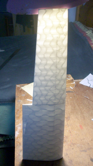
But it is heavy. At 25.6g It slightly heavier than the Depron seagull wing which at 23.2g has nearly twice the area and is quite a bit stiffer too boot!
Lofting a complete wing is an interesting concept that is remarkably simple to do but using an 'infill' pattern is not an efficient use of the material when compared to a commercial fully programmed wing structure as used for example in the Plane Print Seagull.
Now, maybe if I............
For comparison that ruler is 300mm long.
It certainly works, apart from a lengthy print time, giving a nice 'one piece' wing section.
The 3.5% gyroid infill gives adequate support to the wing skin to resist 'handling'.
But it is heavy. At 25.6g It slightly heavier than the Depron seagull wing which at 23.2g has nearly twice the area and is quite a bit stiffer too boot!
Lofting a complete wing is an interesting concept that is remarkably simple to do but using an 'infill' pattern is not an efficient use of the material when compared to a commercial fully programmed wing structure as used for example in the Plane Print Seagull.
Now, maybe if I............
Thanks: Eric, Klipkopwildlife, jon.in.swansea
Please Log in or Create an account to join the conversation.
- jon.in.swansea
-

- Offline
- Elite Member
-

Less
More
- Posts: 766
- Thank you received: 1192
15 Nov 2022 11:04 #3
by jon.in.swansea
Replied by jon.in.swansea on topic Some more lofting
Still - 25g for a half wing is not bad! Quite a sleek beastie. And how does the join work out in the strength side? There is no spar to help distribute the stresses away from the join.
Is one of your future tests a slightly lower infil % but with a printed sleeve for a carbon fibre spar?
Is one of your future tests a slightly lower infil % but with a printed sleeve for a carbon fibre spar?
Thanks: Klipkopwildlife
Please Log in or Create an account to join the conversation.
- Quorneng
-
Topic Author
- Offline
- Forum Master
-
Less
More
- Posts: 9436
- Thank you received: 19043
15 Nov 2022 23:32 #4
by Quorneng
Replied by Quorneng on topic Some more lofting
jon
The simple butt joint is remarkably rigid.
Foamed LW-PLA is actually slightly porous so provided the 'skin' of each wing exactly line up and the glue is strong enough the joint behaves as if the whole wing was printed as one piece.
Not exactly scientific but no problem with the strength of the joint.

It is worth pointing out that a carbon spar would be so much more rigid that the 25g of the LW-PLA would be simply creating the wing shape and contribute little to the strength of the wing. Not an ideal use of materials.
Lofting a wing is a neat concept but at least for me it does not bring a tangible benefit over what I can do currently.
25g may sound light but it is still heavier than a built up Depron wing with over twice the area and that has no spar either.
The simple butt joint is remarkably rigid.
Foamed LW-PLA is actually slightly porous so provided the 'skin' of each wing exactly line up and the glue is strong enough the joint behaves as if the whole wing was printed as one piece.
Not exactly scientific but no problem with the strength of the joint.
It is worth pointing out that a carbon spar would be so much more rigid that the 25g of the LW-PLA would be simply creating the wing shape and contribute little to the strength of the wing. Not an ideal use of materials.
Lofting a wing is a neat concept but at least for me it does not bring a tangible benefit over what I can do currently.
25g may sound light but it is still heavier than a built up Depron wing with over twice the area and that has no spar either.
Thanks: Klipkopwildlife, jon.in.swansea
Please Log in or Create an account to join the conversation.
- Quorneng
-
Topic Author
- Offline
- Forum Master
-
Less
More
- Posts: 9436
- Thank you received: 19043
16 Nov 2022 21:07 #5
by Quorneng
Replied by Quorneng on topic Some more lofting
One further thing I wanted to try was lofting an elliptical wing using just 4 discreet sized ribs at specific positions and then let the lofting process join them up.
After quite a bit of trial and error I ended up with a sort of "Spitfire" wing shape.

Printed out as a test at 100 mm root to tip.

Even at that small size it still took 41 minutes to print. It weighs 2.6 g.
Interesting rather than practical as the loft made a bit of a mess of the thin trailing edge. It needed some trimming and sanding.
Scaled up to the full 240 mm height limit of the printer it would take 3.5 hours and weigh 20g.
After quite a bit of trial and error I ended up with a sort of "Spitfire" wing shape.
Printed out as a test at 100 mm root to tip.
Even at that small size it still took 41 minutes to print. It weighs 2.6 g.
Interesting rather than practical as the loft made a bit of a mess of the thin trailing edge. It needed some trimming and sanding.
Scaled up to the full 240 mm height limit of the printer it would take 3.5 hours and weigh 20g.
Thanks: jon.in.swansea
Please Log in or Create an account to join the conversation.
- Klipkopwildlife
-

- Offline
- Administrator
-

- I'm supposed to be retired!
17 Nov 2022 07:16 #6
by Klipkopwildlife
Do it now, you may never get another chance
Replied by Klipkopwildlife on topic Some more lofting
The trailing edge should be at the back of your build plate, then you place the Z seam at the back.
Do it now, you may never get another chance
Please Log in or Create an account to join the conversation.
- Quorneng
-
Topic Author
- Offline
- Forum Master
-
Less
More
- Posts: 9436
- Thank you received: 19043
17 Nov 2022 10:36 - 17 Nov 2022 10:37 #7
by Quorneng
Replied by Quorneng on topic Some more lofting
Klippy
I fear it is the way CURA treats a lofted file that is the primary cause of the trailing edge problem.
Lofting in FreeCad creates a unique hollow single wall structure.

A normally generated FREE CAD file is portrayed as a solid.
It looks like the lofted shape is created by overlaying a series of mathematically generated shapes that are smoothed together, hence the 'construction' lines on the lofted surface.
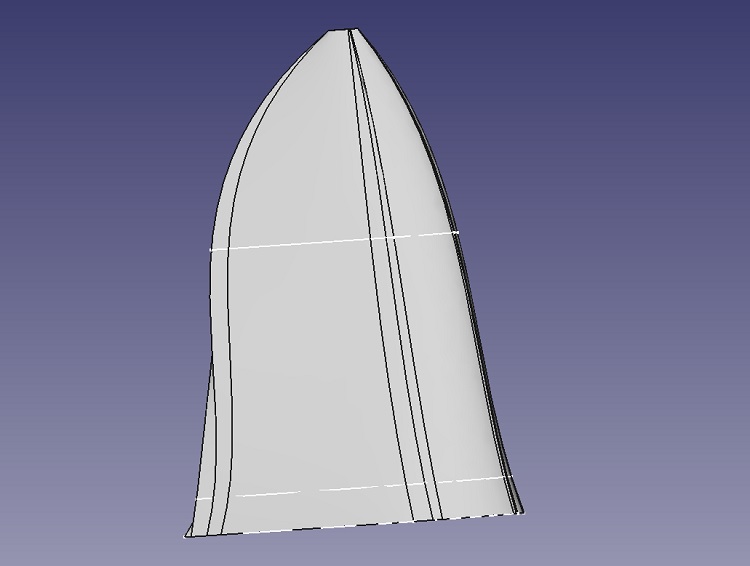
This process can lead to some odd surface profiles.
CURA seems to have difficulty exactly following the CAD file that is transferred into an STL file.
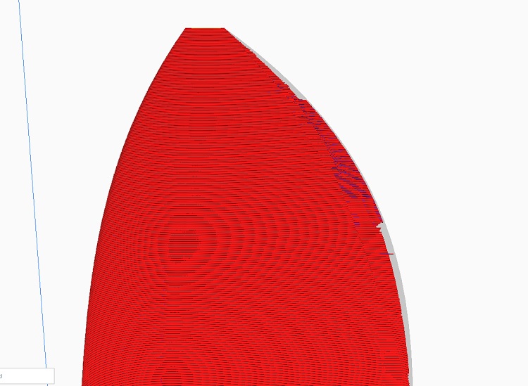
It is normal to not print a shape that falls below a certain dimension but on the lofted trailing edge this occurs at different points as it works along the edge. I can only assume that the lofted trailing edge thickness actually varies. It is this 'ragged' trailing edge effect that requires trimming.
To make matters worse CURA will only print a lofted subject if it is positioned vertically. In any other orientation large parts of the object are simply omitted regardless of what print parameters used.
Lofting is clever but does have limitations. To be fair the FreeCad tutorial does recommend that the changes in section should be limited between each 'primitive' and each should have a similar number of generated faces.
The wing sections I am using are all similar being created from 4 ellipse arcs however creating a mathematically smoothed surfaces from what is already a mathematically complex shape my be stretching its capability.
That's enough of that. My brain hurts!
I fear it is the way CURA treats a lofted file that is the primary cause of the trailing edge problem.
Lofting in FreeCad creates a unique hollow single wall structure.
A normally generated FREE CAD file is portrayed as a solid.
It looks like the lofted shape is created by overlaying a series of mathematically generated shapes that are smoothed together, hence the 'construction' lines on the lofted surface.
This process can lead to some odd surface profiles.
CURA seems to have difficulty exactly following the CAD file that is transferred into an STL file.
It is normal to not print a shape that falls below a certain dimension but on the lofted trailing edge this occurs at different points as it works along the edge. I can only assume that the lofted trailing edge thickness actually varies. It is this 'ragged' trailing edge effect that requires trimming.
To make matters worse CURA will only print a lofted subject if it is positioned vertically. In any other orientation large parts of the object are simply omitted regardless of what print parameters used.
Lofting is clever but does have limitations. To be fair the FreeCad tutorial does recommend that the changes in section should be limited between each 'primitive' and each should have a similar number of generated faces.
The wing sections I am using are all similar being created from 4 ellipse arcs however creating a mathematically smoothed surfaces from what is already a mathematically complex shape my be stretching its capability.
That's enough of that. My brain hurts!
Last edit: 17 Nov 2022 10:37 by Quorneng.
Thanks: Klipkopwildlife, jon.in.swansea
Please Log in or Create an account to join the conversation.
- jon.in.swansea
-
- Offline
- Elite Member
-
Less
More
- Posts: 766
- Thank you received: 1192
19 Nov 2022 18:51 #8
by jon.in.swansea
Replied by jon.in.swansea on topic Some more lofting
I am enjoying seeing your exploration of lofting. I can relate to the trial-and-error side of lofting!
Thanks: Klipkopwildlife
Please Log in or Create an account to join the conversation.
- jon.in.swansea
-
- Offline
- Elite Member
-
Less
More
- Posts: 766
- Thank you received: 1192
19 Nov 2022 18:58 #9
by jon.in.swansea
Replied by jon.in.swansea on topic Some more lofting
What are you using for glue?
I am wondering about getting into this LW-PLA universe. For instance - the oval fuselages I have been working with have gotten simplified down to a single perimeter layer and ~6% gyro infill with standard PLA (but with the carbon boom running the length of the fuselage to give it great resistance to sudden deceleration). Most builds I see seem to keep the standard PLA for the fuselage and only go to LW for the lifting surfaces - is it actually up to use in more of the fuselage?
I am wondering about getting into this LW-PLA universe. For instance - the oval fuselages I have been working with have gotten simplified down to a single perimeter layer and ~6% gyro infill with standard PLA (but with the carbon boom running the length of the fuselage to give it great resistance to sudden deceleration). Most builds I see seem to keep the standard PLA for the fuselage and only go to LW for the lifting surfaces - is it actually up to use in more of the fuselage?
Thanks: Klipkopwildlife
Please Log in or Create an account to join the conversation.
- jon.in.swansea
-
- Offline
- Elite Member
-
Less
More
- Posts: 766
- Thank you received: 1192
19 Nov 2022 19:02 #10
by jon.in.swansea
Replied by jon.in.swansea on topic Some more lofting
About the ragged trailing edge.... I notice that sometimes when printing props. Some designs have such a sharp trailing edge that is gets into that disappearing bit of the universe. I know you are a CURA guy.... and the Prusa slicer does not seem to have an issue with lofts that are not vertically oriented. The latest version seems to have a different numerical engine for figuring out perimeter layers that are quite thin - it reduces the flow in those areas.
Thanks: Klipkopwildlife, Quorneng
Please Log in or Create an account to join the conversation.
- Quorneng
-
Topic Author
- Offline
- Forum Master
-
Less
More
- Posts: 9436
- Thank you received: 19043
20 Nov 2022 01:00 #11
by Quorneng
Replied by Quorneng on topic Some more lofting
jon
I note that the Plane Print Sea gull uses a mixture of LW-PLA and PLA in the fuselage for the EDF powered version. LW-PLA is more flexible and softer than PLA so it might be required for any area under high stress or likely to abrasion.
I am using Technicqll foam safe. It is similar to UHU POR but unlike POR in 24 hours it dries rock hard so it works well for things like wing butt joints in the slightly porous surface of LW-PLA.
Thanks: Klipkopwildlife, jon.in.swansea
Please Log in or Create an account to join the conversation.
- jon.in.swansea
-
- Offline
- Elite Member
-
Less
More
- Posts: 766
- Thank you received: 1192
20 Nov 2022 13:54 #12
by jon.in.swansea
Replied by jon.in.swansea on topic Some more lofting
Ah, I have a tube of the Technicqll! Seeing your bending demo it certainly has grip.
If using with standard PLA should I be roughing up that surface since it is less porous?
If using with standard PLA should I be roughing up that surface since it is less porous?
Thanks: Klipkopwildlife
Please Log in or Create an account to join the conversation.
- Klipkopwildlife
-
- Offline
- Administrator
-
- I'm supposed to be retired!
20 Nov 2022 16:08 #13
by Klipkopwildlife
Do it now, you may never get another chance
Replied by Klipkopwildlife on topic Some more lofting
All surfaces should be lightly sanded prior to gluing. Roughing up only leads to gap filling problems.
Do it now, you may never get another chance
Please Log in or Create an account to join the conversation.
- Quorneng
-
Topic Author
- Offline
- Forum Master
-
Less
More
- Posts: 9436
- Thank you received: 19043
20 Nov 2022 17:20 #14
by Quorneng
Replied by Quorneng on topic Some more lofting
I have found that ordinary Cyano works well on PLA provided the surfaces are really smooth and in close contact. I suspect the porosity of LW-PLA does need a 'filling' glue to work well.
A bit more lofting.
By giving each 'primitive' rib a positive thickness at its trailing edge (0.4 mm) the loft tailing edge is now continuous.
The elliptical wing printed at 200 mm root to tip next to the 100mm first attempt.
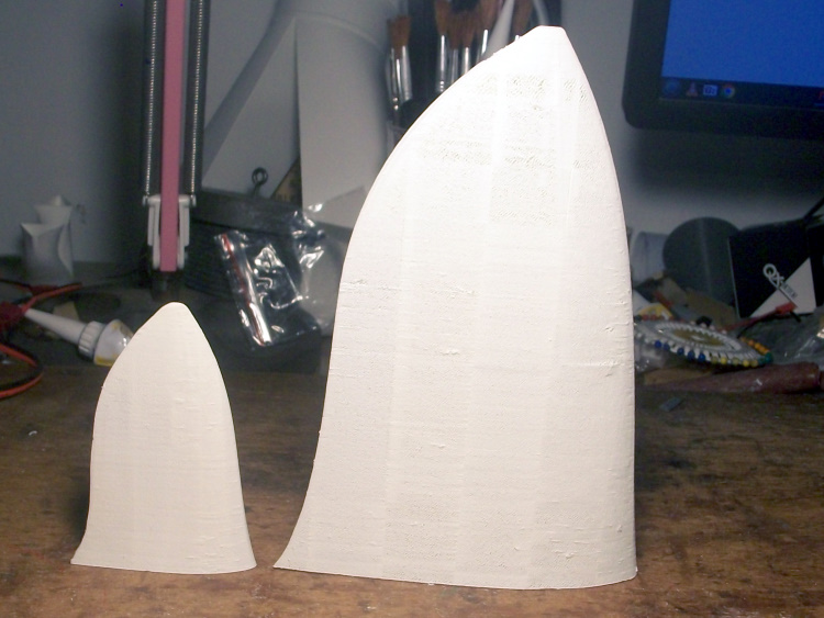
I pushed up the nozzle temperature to 220 C, reduced the flow to 50% and used a 'trick' fill to give 5 equally spaced shear webs. In addition the root rib face is inclined to give 2 degrees dihedral should I wish to print the other half.
It weighs 9.9 g and to 2 hrs 18 min to print.
A bit more lofting.
By giving each 'primitive' rib a positive thickness at its trailing edge (0.4 mm) the loft tailing edge is now continuous.
The elliptical wing printed at 200 mm root to tip next to the 100mm first attempt.
I pushed up the nozzle temperature to 220 C, reduced the flow to 50% and used a 'trick' fill to give 5 equally spaced shear webs. In addition the root rib face is inclined to give 2 degrees dihedral should I wish to print the other half.
It weighs 9.9 g and to 2 hrs 18 min to print.
Thanks: Klipkopwildlife, jon.in.swansea
Please Log in or Create an account to join the conversation.
- Quorneng
-
Topic Author
- Offline
- Forum Master
-
Less
More
- Posts: 9436
- Thank you received: 19043
28 Nov 2022 00:32 #15
by Quorneng
Replied by Quorneng on topic Some more lofting
Not strictly lofting but still trying to produce a printed light and strong wing.
Even with LW-PLA the direction of the bead still makes a considerable difference to the bending strength of a wing so printing it horizontally is better than the conventional vertical, however it needs "support" unless the wing is entirely flat bottomed.
My solution is to print the wing in two parts split along the nominal spar line flat on the bed.
first a test wing 200 mm span by 138 mm chord.

It is then "sunk" through the bed by 38 mm so the 96 mm tall rear section is printed.
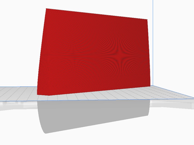
By careful selection of the 'fill' ribs can be added.
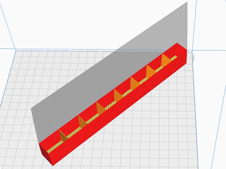
The wing is then turned over 180 degrees and the 'sink' adjusted so the 42 mm tall nose section can be printed.
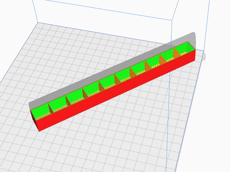
As this is in effect a "D" box section it has closer spaced ribs and a double thick wall and base.
The two parts take just under 5 hours to print.
Glued together and backlight you can detect the different rib count and skin thickness

It weigh 20 g.
Another advantage is the outer sections of the wing can have lighter fills where the same bending strength is not requited and to save weight.
It follows that a 5 section 1000 mm span 138 mm chord wing would weigh a bit less than 100g. It would take about 25 hours to print.
Not bad but in comparison the bigger XPS wing of the Blue Dragon has a span of 1130 mm and a mean chord 150 mm (1.7 bigger area) weighs 105 g but that includes its 2 aileron servos. :woohoo:
What I think this shows is that using sheet foam to create a 'built up' wing beats LW-PLA by considerable margin for both weight and strength unless a shape is required that can only be realistically generated using a 3D printer.
.
Even with LW-PLA the direction of the bead still makes a considerable difference to the bending strength of a wing so printing it horizontally is better than the conventional vertical, however it needs "support" unless the wing is entirely flat bottomed.
My solution is to print the wing in two parts split along the nominal spar line flat on the bed.
first a test wing 200 mm span by 138 mm chord.
It is then "sunk" through the bed by 38 mm so the 96 mm tall rear section is printed.
By careful selection of the 'fill' ribs can be added.
The wing is then turned over 180 degrees and the 'sink' adjusted so the 42 mm tall nose section can be printed.
As this is in effect a "D" box section it has closer spaced ribs and a double thick wall and base.
The two parts take just under 5 hours to print.
Glued together and backlight you can detect the different rib count and skin thickness
It weigh 20 g.
Another advantage is the outer sections of the wing can have lighter fills where the same bending strength is not requited and to save weight.
It follows that a 5 section 1000 mm span 138 mm chord wing would weigh a bit less than 100g. It would take about 25 hours to print.
Not bad but in comparison the bigger XPS wing of the Blue Dragon has a span of 1130 mm and a mean chord 150 mm (1.7 bigger area) weighs 105 g but that includes its 2 aileron servos. :woohoo:
What I think this shows is that using sheet foam to create a 'built up' wing beats LW-PLA by considerable margin for both weight and strength unless a shape is required that can only be realistically generated using a 3D printer.
.
Thanks: Eric, jon.in.swansea
Please Log in or Create an account to join the conversation.
Time to create page: 1.126 seconds