
- Posts: 13726
- Thank you received: 14470
Some more lofting
- Eric
-

- Offline
- Moderator
-

Less
More
28 Nov 2022 07:46 - 28 Nov 2022 07:48 #16
by Eric
if you are calm and collected when all about you are going berserk - you've missed something important!
Replied by Eric on topic Some more lofting
Technically interesting - but I think I'll stay with balsa and ply. It may be heavier, but I understand the materials!
-
25 hours to print half a wing? I've built an entire model from sticks and planks in less than that! [badass]
-
25 hours to print half a wing? I've built an entire model from sticks and planks in less than that! [badass]
if you are calm and collected when all about you are going berserk - you've missed something important!
Last edit: 28 Nov 2022 07:48 by Eric. Reason: typo and added a word
Thanks: Klipkopwildlife
Please Log in or Create an account to join the conversation.
- Quorneng
-
 Topic Author
- Offline
- Forum Master
-

Less
More
- Posts: 9436
- Thank you received: 19043
28 Nov 2022 13:01 #17
by Quorneng
Replied by Quorneng on topic Some more lofting
25 hours would print a full 1m wing but I agree I can build faster than that with the advantage that the time taken is not directly proportional to size which with printing is is, unless you have multiple printers! :woohoo:
Thanks: Eric, Klipkopwildlife
Please Log in or Create an account to join the conversation.
- Quorneng
-
Topic Author
- Offline
- Forum Master
-
Less
More
- Posts: 9436
- Thank you received: 19043
01 Dec 2022 16:41 #18
by Quorneng
Replied by Quorneng on topic Some more lofting
Having experimented some more it occurred to me the plane that could benefit from a lofted duct would be the Sea Hawk with its bifurcated inlets, exhaust and the EDF all squashed within the length of the wing root chord.
The ducts were printed but I rather sacrificed the inlet geometry to achieve a reasonable exhaust.
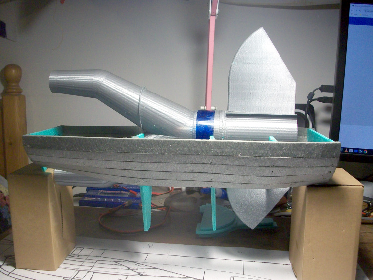
This construction picture rather shows the problem with the inlet air having to turn virtually through 90 degrees and then back again to face the EDF inlet.
Indeed I was surprised how well it did perform but it was noticeable that the fan was almost stalled at full power static but sounded much happier at even slightly reduced throttle when in flight.
I was hoping that by lofting a reasonably smooth duct could be achieved despite the limited space.
The intention would be to print the duct is parts and then glue it all together.
The inlet was the problem area but by moving the EDF back by 40 mm a reasonable duct was possible.

The loss of 40 mm in the exhaust length still allowed a smooth duct likely a bit more efficient than the longer original.

Each of these ducts can be single wall 'vase' printed although the inlet would need significant support from the fuselage former to prevent negative pressure collapse.
To give an idea this show the original and lofted versions side by side.
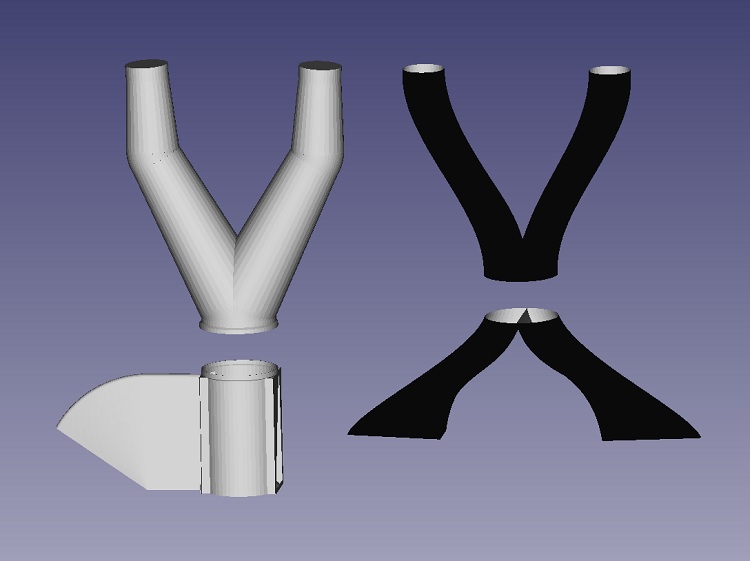
Bizarrely a lofted stl file is displayed with a black skin in FreeCad.
Printed in LW-PLA the weight saving is substantial. The PLA printed duct came in close to 40 g or about 2/3 the weight of the EDF.
It looks like the improved LW-PLA duct will weigh less than 20 g.
A printed inlet half.
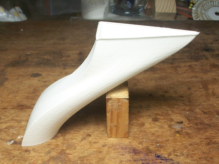
It weighs 2.8 g!
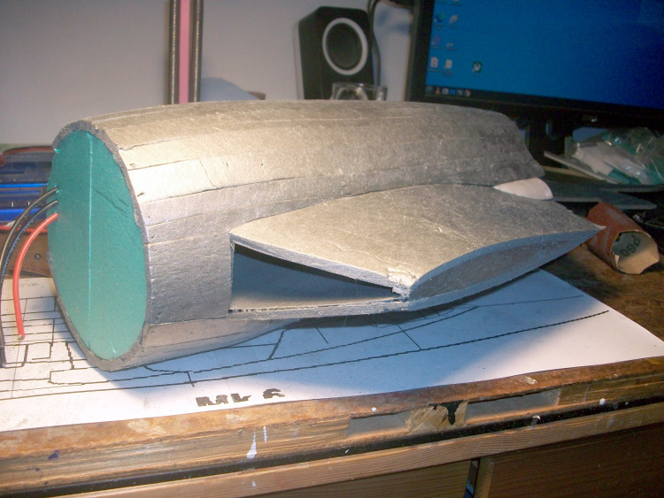
My plan if and when I am happy with the duct will be cut of the nose, tail and wings, build a new fuselage centre section and glue it all back together.
Not quite a daft as it sounds as that it was how it was built originally. :ohmy:
The ducts were printed but I rather sacrificed the inlet geometry to achieve a reasonable exhaust.
This construction picture rather shows the problem with the inlet air having to turn virtually through 90 degrees and then back again to face the EDF inlet.
Indeed I was surprised how well it did perform but it was noticeable that the fan was almost stalled at full power static but sounded much happier at even slightly reduced throttle when in flight.
I was hoping that by lofting a reasonably smooth duct could be achieved despite the limited space.
The intention would be to print the duct is parts and then glue it all together.
The inlet was the problem area but by moving the EDF back by 40 mm a reasonable duct was possible.
The loss of 40 mm in the exhaust length still allowed a smooth duct likely a bit more efficient than the longer original.
Each of these ducts can be single wall 'vase' printed although the inlet would need significant support from the fuselage former to prevent negative pressure collapse.
To give an idea this show the original and lofted versions side by side.
Bizarrely a lofted stl file is displayed with a black skin in FreeCad.
Printed in LW-PLA the weight saving is substantial. The PLA printed duct came in close to 40 g or about 2/3 the weight of the EDF.
It looks like the improved LW-PLA duct will weigh less than 20 g.
A printed inlet half.
It weighs 2.8 g!
My plan if and when I am happy with the duct will be cut of the nose, tail and wings, build a new fuselage centre section and glue it all back together.
Not quite a daft as it sounds as that it was how it was built originally. :ohmy:
Thanks: Eric, Klipkopwildlife
Please Log in or Create an account to join the conversation.
- jon.in.swansea
-

- Offline
- Elite Member
-

Less
More
- Posts: 766
- Thank you received: 1192
22 Feb 2023 16:33 #19
by jon.in.swansea
Replied by jon.in.swansea on topic Some more lofting
I do like the idea of splitting the wing along the line of the spar so the extrusion is running 90 degrees from the usual vertical wing print!
It should also be easier to get ribs in with my slice the shell with thin elements approach. And lots of area for gluing the leading and trailing sections.
It should also be easier to get ribs in with my slice the shell with thin elements approach. And lots of area for gluing the leading and trailing sections.
Thanks: Klipkopwildlife
Please Log in or Create an account to join the conversation.
- Quorneng
-
Topic Author
- Offline
- Forum Master
-
Less
More
- Posts: 9436
- Thank you received: 19043
22 Feb 2023 19:25 #20
by Quorneng
Replied by Quorneng on topic Some more lofting
jon
That was exactly what I was looking at with a two part wing split along the spar line so the print filaments are laid along the line of the bending loads.
As you point out a conventional 'fill' can easily produce a wing rib type structure, something like this.
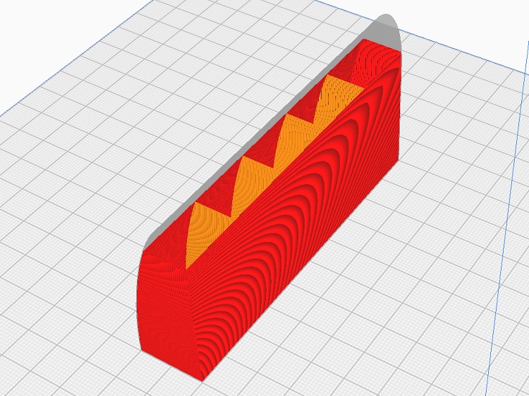
It does get a bit more complex if you include accommodation for an inserted spar but it still only needs basic CAD instructions..
That was exactly what I was looking at with a two part wing split along the spar line so the print filaments are laid along the line of the bending loads.
As you point out a conventional 'fill' can easily produce a wing rib type structure, something like this.
It does get a bit more complex if you include accommodation for an inserted spar but it still only needs basic CAD instructions..
Thanks: Klipkopwildlife, jon.in.swansea
Please Log in or Create an account to join the conversation.
Time to create page: 0.383 seconds