
- Posts: 3094
- Thank you received: 2182
×
Flying models without a radio
Fixing WIngs and U/Cs to a FF Scale Model
- Ex-Member
- Topic Author
- Visitor
-

13 Sep 2013 12:26 #1
by Ex-Member
Fixing WIngs and U/Cs to a FF Scale Model was created by Ex-Member
When compared to sports models, FF Scale models tend to have less stability and be heavier. Therefore, to survive for more than a few flights, the components must have some built in flexibility and be able to "knock off" when the inevitable arrival with terra firma occurs. Most kits for FF Scale models show the completed model as a single assembly. It's easy to produce such a construction method in kit form, but it's not practical for a flying model. So, I've started this thread to post a few ideas, if the Mods believe it should sit somewhere else, then please feel free to move it.
I'll start with a bi-plane, then when I have more time, I'll add a monoplane or two...........
I'll start with a bi-plane, then when I have more time, I'll add a monoplane or two...........
Please Log in or Create an account to join the conversation.
- Ex-Member
- Topic Author
- Visitor
-
13 Sep 2013 12:41 - 13 Sep 2013 12:46 #2
by Ex-Member
Replied by Ex-Member on topic Fixing WIngs and U/Cs to a FF Scale Model
The biplane I've chosen is the Gannet I started many years ago and tried to complete for this years Nationals. An incompatibility issue with the paint led to stripping off the tissue, so the model is in an ideal state to photograph to show the method of fixing of the U/C and Wings.
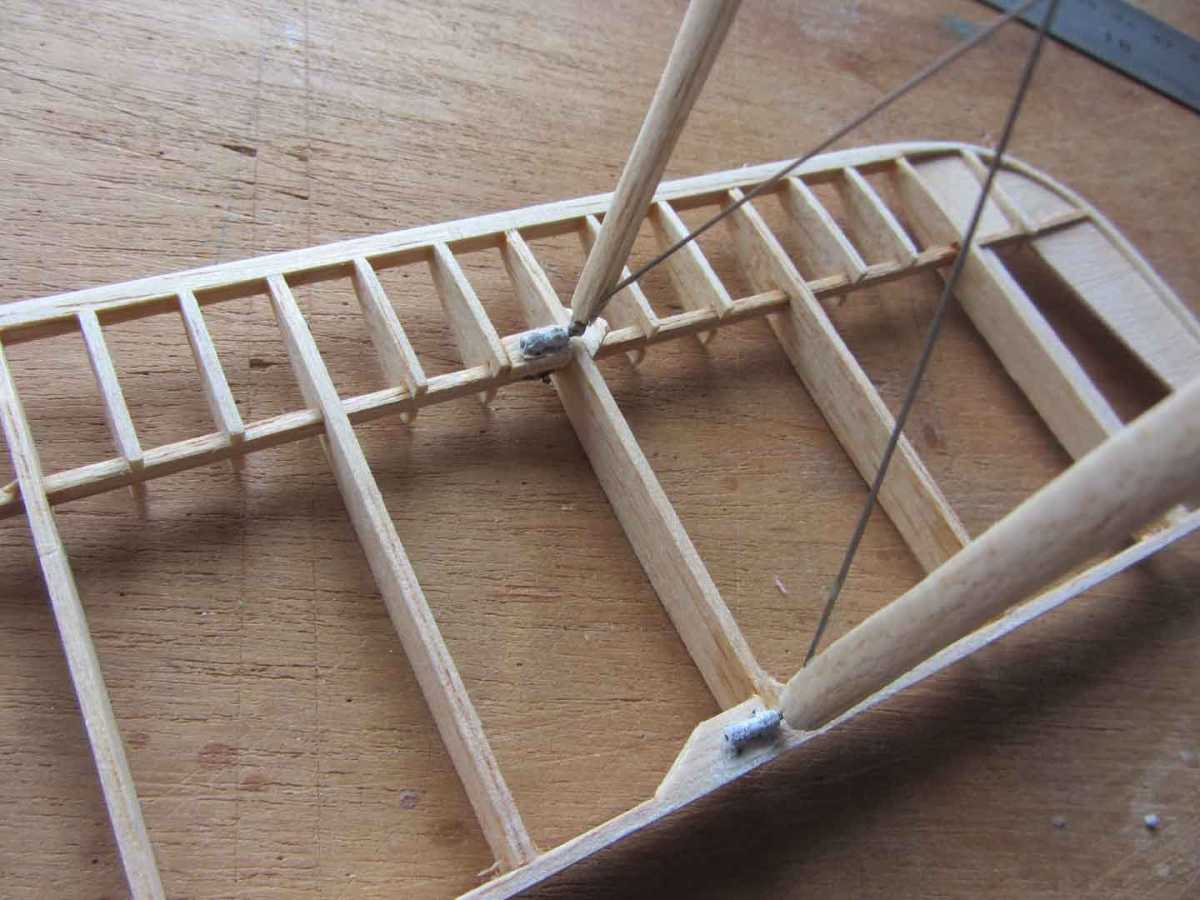
The principal is to have the struts bent from thin wire (21 swg or 1/32" in this case) which slots into tubes in the respective components. Once the strut size has been fixed, rigging wires are made from thin wire (0.015 guitar string for example) soldered in place to hold the shape and the strut wires are then sheathed in balsa. The first pic shows 1/16" ali tube (1/32" inside dia) bound to the lower surface of the upper wing centre section. I normally cover the surface first, then bind the tubes in place before covering the other side. However, having now stripped the model, I'll have to recover it round the tubes.

The second pic shows the same centre section turned over with both sets of struts fitted. The wing tubes are also 1/16" dia ali and have been bound to the spars. The pic also shows the 1/32" wire dowels that support the wing.

Next pic shows the wing in place, held by small magnets (see later). Note that the dihedral is fixed by the angle of the tube in the wing spar and not by bending the wire.

The interplane struts are made in the same way as the centre section struts and slot into tubes fixed to the wing.
The U'C is also on 1/32" wire - shown here fitted but not pushed home. Note that the U/C mounting tube is bound to the fuselage cross piece.

Finally, we have an end view of the wing rib showing the mounting tubes and holding magnets.

The above results in quite a floppy set-up, but it will be held together by working rigging made from fishing line fixed to hooks at one end and wrapped around the wing struts at the other. The rigging will then hold the struts in place as well as setting the dihedral.
AN alternate method is to fix the wires to the wing rather than the tubes and have holes in the bottom of the struts to slip over the wires - the struts in this case can be made from a thin ply/balsa sandwich. It all adds up to the same thing in the end, but I prefer to have the tubes on the wing.
If a stiffer setup is required, then use thicker wire or carbon dowels and rig the wing with shearing elastic.
The principal is to have the struts bent from thin wire (21 swg or 1/32" in this case) which slots into tubes in the respective components. Once the strut size has been fixed, rigging wires are made from thin wire (0.015 guitar string for example) soldered in place to hold the shape and the strut wires are then sheathed in balsa. The first pic shows 1/16" ali tube (1/32" inside dia) bound to the lower surface of the upper wing centre section. I normally cover the surface first, then bind the tubes in place before covering the other side. However, having now stripped the model, I'll have to recover it round the tubes.
The second pic shows the same centre section turned over with both sets of struts fitted. The wing tubes are also 1/16" dia ali and have been bound to the spars. The pic also shows the 1/32" wire dowels that support the wing.
Next pic shows the wing in place, held by small magnets (see later). Note that the dihedral is fixed by the angle of the tube in the wing spar and not by bending the wire.
The interplane struts are made in the same way as the centre section struts and slot into tubes fixed to the wing.
The U'C is also on 1/32" wire - shown here fitted but not pushed home. Note that the U/C mounting tube is bound to the fuselage cross piece.
Finally, we have an end view of the wing rib showing the mounting tubes and holding magnets.
The above results in quite a floppy set-up, but it will be held together by working rigging made from fishing line fixed to hooks at one end and wrapped around the wing struts at the other. The rigging will then hold the struts in place as well as setting the dihedral.
AN alternate method is to fix the wires to the wing rather than the tubes and have holes in the bottom of the struts to slip over the wires - the struts in this case can be made from a thin ply/balsa sandwich. It all adds up to the same thing in the end, but I prefer to have the tubes on the wing.
If a stiffer setup is required, then use thicker wire or carbon dowels and rig the wing with shearing elastic.
Last edit: 13 Sep 2013 12:46 by Ex-Member.
Please Log in or Create an account to join the conversation.
- Ex-Member
- Visitor
-
13 Sep 2013 13:53 #3
by Ex-Member
Replied by Ex-Member on topic Fixing WIngs and U/Cs to a FF Scale Model
Thank you Andy.
very concise and clear.
just got to do it now. hahahaha
very concise and clear.
just got to do it now. hahahaha
Please Log in or Create an account to join the conversation.
- Garry Pollard
- Visitor
-
13 Sep 2013 13:57 #4
by Garry Pollard
Replied by Garry Pollard on topic Fixing WIngs and U/Cs to a FF Scale Model
Fine where it is Andy, and most interesting .
Garry
Garry
Please Log in or Create an account to join the conversation.
- Ex-Member
- Topic Author
- Visitor
-
14 Sep 2013 13:35 #5
by Ex-Member
Replied by Ex-Member on topic Fixing WIngs and U/Cs to a FF Scale Model
Next one is a hi-wing monoplane with struts, the Earl Stahl Taylorcraft. The plan is available on the net - www.theplanpage.com/esp/tcraft.htm - the plan download icon is at the bottom of the page.
I built mine for the 2012 Flying Aces comp in the USA, but it's also eligible for SAM 35 Earl Stahl competition, SAM 35 Masefield Trophy and as it was apparently kitted, the new BMFA outdoor scale FF Kit Scale competition and if built below 200gm (mine is around 120gm) BMFA Scale Indoor Kit Scale comp as well. My model was coloured tissue covered with markings sprayed on with colour dope.
A word of warning, this model flies well. It's more than capable of over a minute in still air and numerous examples have been lost in thermals, so consider fitting a DT if you intend flying outdoors!
Here's a couple of general views, next post will describe the UC and Wing fittings - note that the tailplane has been banded on to facilitate easy transport and any required change of incidence. Exposed bands are normally frowned on in scale circles, but as this model was never intended to be statically judged, I felt it was appropriate.
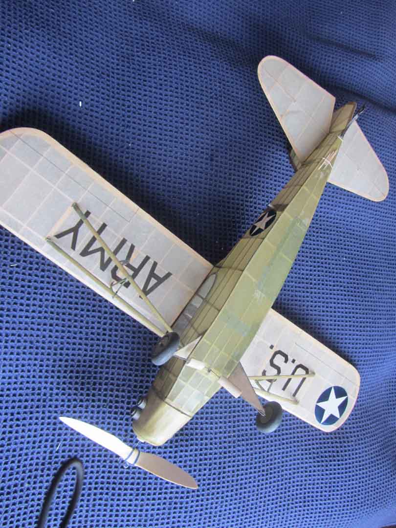
I built mine for the 2012 Flying Aces comp in the USA, but it's also eligible for SAM 35 Earl Stahl competition, SAM 35 Masefield Trophy and as it was apparently kitted, the new BMFA outdoor scale FF Kit Scale competition and if built below 200gm (mine is around 120gm) BMFA Scale Indoor Kit Scale comp as well. My model was coloured tissue covered with markings sprayed on with colour dope.
A word of warning, this model flies well. It's more than capable of over a minute in still air and numerous examples have been lost in thermals, so consider fitting a DT if you intend flying outdoors!
Here's a couple of general views, next post will describe the UC and Wing fittings - note that the tailplane has been banded on to facilitate easy transport and any required change of incidence. Exposed bands are normally frowned on in scale circles, but as this model was never intended to be statically judged, I felt it was appropriate.
Attachment Taylorcrafttopsf.JPG not found
Please Log in or Create an account to join the conversation.
- Ex-Member
- Topic Author
- Visitor
-
14 Sep 2013 14:01 - 04 May 2017 09:12 #6
by Ex-Member
Replied by Ex-Member on topic Fixing WIngs and U/Cs to a FF Scale Model
First pic shows the method of fixing the lower ends of the struts to the fus by hidden rubber bands and the UC wires slotting into tubes also in the lower fus. UC wires are 1/32". This would be too thin if the model was free standing, but there's a bracing strut underneath (also of 1/32" wire, that helps support the model. The strut wires are bound to the strut by tissue and are about 1" long - wire running the length of the strut would be too heavy.

Pic 2 shows the airframe uncovered, note the UC wires without the balsa fairing between the legs going into ali tubes bound to fus cross piece..

Pic 3 - strut pulled into fus by hidden band:

Pic 4 - Wing end of struts fixed by 1/32" wire into 1/16" O/D tube similar to the Gannet. Tube is bound and cyano'd to wing with thin cotton thread. Wire is bound to strut with tissue.

Pic 5 - Wing fixing, again by hidden band. Dowels are 1/4" balsa going into 1/64" plywood root ribs in the fus. Dowels are a loose fit to allow wing to 'break' off in a hard arrival.

Pic 2 shows the airframe uncovered, note the UC wires without the balsa fairing between the legs going into ali tubes bound to fus cross piece..
Pic 3 - strut pulled into fus by hidden band:
Pic 4 - Wing end of struts fixed by 1/32" wire into 1/16" O/D tube similar to the Gannet. Tube is bound and cyano'd to wing with thin cotton thread. Wire is bound to strut with tissue.
Pic 5 - Wing fixing, again by hidden band. Dowels are 1/4" balsa going into 1/64" plywood root ribs in the fus. Dowels are a loose fit to allow wing to 'break' off in a hard arrival.
Last edit: 04 May 2017 09:12 by Ex-Member.
Please Log in or Create an account to join the conversation.
- Ex-Member
- Topic Author
- Visitor
-
14 Sep 2013 14:26 - 14 Sep 2013 14:30 #7
by Ex-Member
Replied by Ex-Member on topic Fixing WIngs and U/Cs to a FF Scale Model
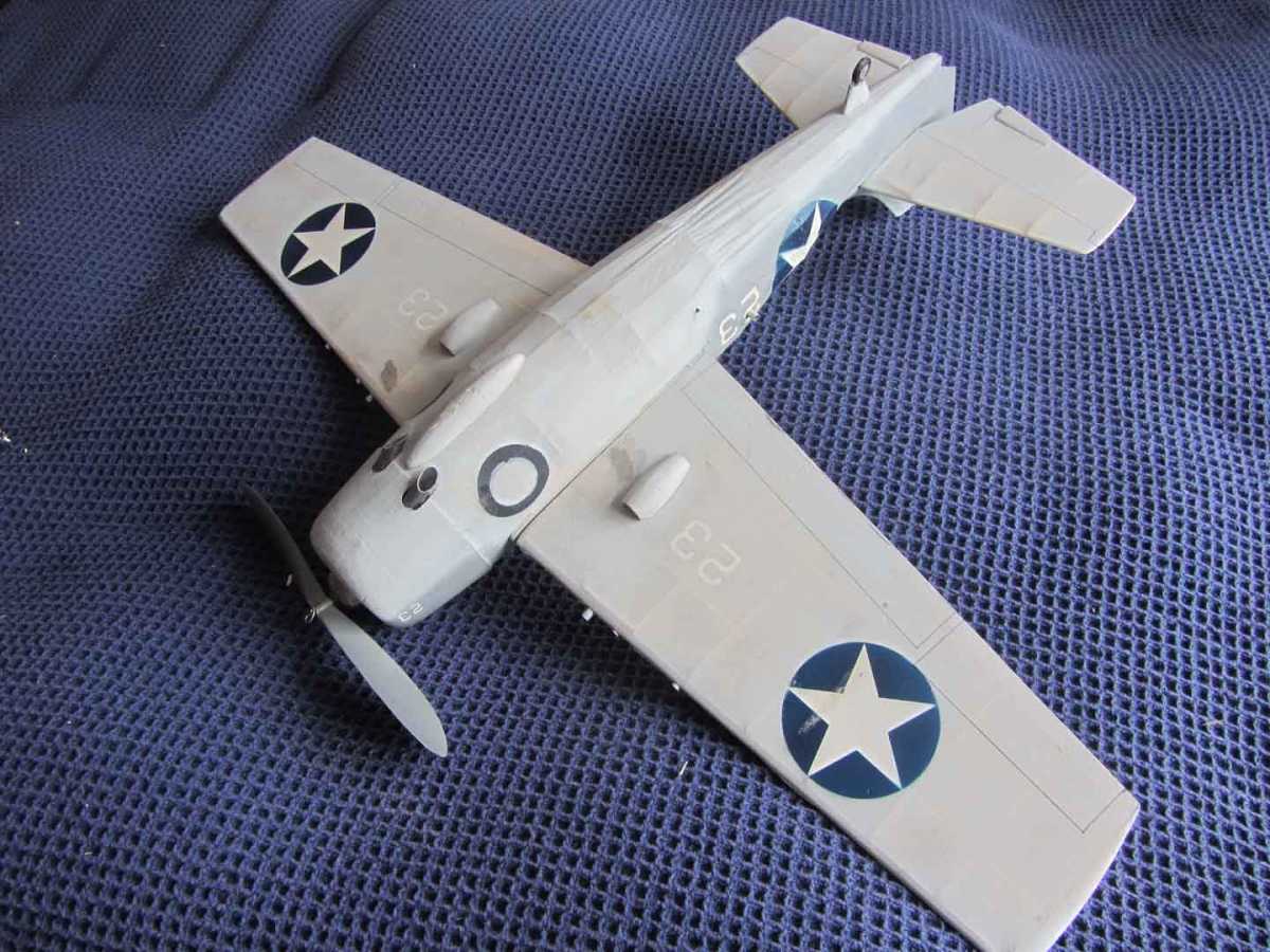
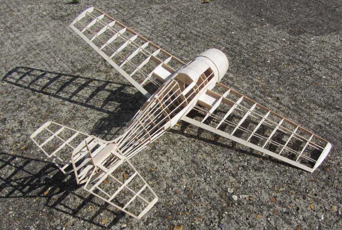
Next one is a low (mid really) wing monoplane with no struts - a 29" WIldcat. The model was built for the Battle of Midway comp at the 1012 Flying Aces event in the USA. I've hankered after a WIldcat for sometime and the comp gave me the impetus I needed. It was an outdoor comp and I figured a model of around 30" would be best to cope with the weather and break down to a reasonable size for the suitcase. I eventually chose the Model Builder plan from their 1974 Book of 1/24" Flying Scale Models of WWII. The original model was too small and one piece, so I upped it by 50% and made the wings and tail removable. I also thinned the wing section a little by redrawing it as a Clark Y as I considered the original to be too thick. Model is 1/18th scale giving a span of about 28".
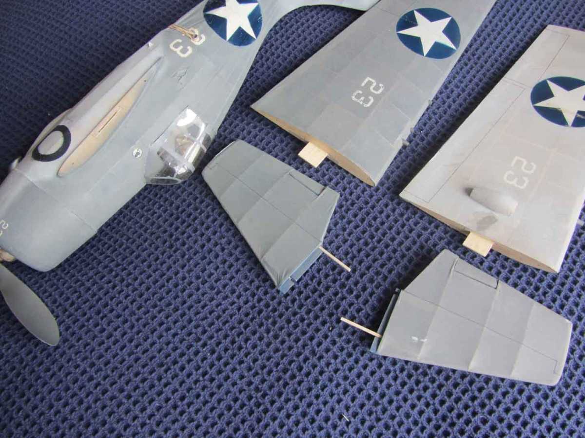
To make the wings of a cantilever monoplane "knock off" requires a tongue and box fixing method. Wire in a tube woould hold the wing posision, but wouldn't allow the wing to bend back if required on arrival.
In this case, I built a box from hard 1/16" balsa, cut it into four pieces and cemented each into the fuselage and respective wings. The tongue was made from balsa of similar thickness and slides into both boxes to hold the wing. It's broken several times in use, but the wings are still in one piece so I rest my case!
The tailplane is built on a 3/32" sq balsa structure with ribs added to thicken the profile. Two 3/32" sq holes were left in each half, which allows them to be joined with 3/32" balsa when assembled. Again, no flight damage has occurred to the tailplane during use.
I haven't bothered with any fixing other than the tongues which has led to two accidents. On one, the wing was not fully home on launch and the tongue broke as flight loads came onto the airframe - the model crashed but there was no damage noted. On the other, the tailplane came off in flight. There was no significant effect as the first half let go, but there was significant pitch down as the second half departed! The model fluttered to the ground with no damage.
First two pics are general views:
Pic 3 shows wings, tailplane and fus with tongues protruding
Pic 4 is the uncovered airframe. Note size of wing box and strengthening round tailplane boxes.
Pic 5 shows wing root in fus and fitting of wing box.

To make the wings of a cantilever monoplane "knock off" requires a tongue and box fixing method. Wire in a tube woould hold the wing posision, but wouldn't allow the wing to bend back if required on arrival.
In this case, I built a box from hard 1/16" balsa, cut it into four pieces and cemented each into the fuselage and respective wings. The tongue was made from balsa of similar thickness and slides into both boxes to hold the wing. It's broken several times in use, but the wings are still in one piece so I rest my case!
The tailplane is built on a 3/32" sq balsa structure with ribs added to thicken the profile. Two 3/32" sq holes were left in each half, which allows them to be joined with 3/32" balsa when assembled. Again, no flight damage has occurred to the tailplane during use.
I haven't bothered with any fixing other than the tongues which has led to two accidents. On one, the wing was not fully home on launch and the tongue broke as flight loads came onto the airframe - the model crashed but there was no damage noted. On the other, the tailplane came off in flight. There was no significant effect as the first half let go, but there was significant pitch down as the second half departed! The model fluttered to the ground with no damage.
First two pics are general views:
Attachment WIldcattopsf.JPG not found
Pic 3 shows wings, tailplane and fus with tongues protruding
Pic 4 is the uncovered airframe. Note size of wing box and strengthening round tailplane boxes.
Pic 5 shows wing root in fus and fitting of wing box.
Last edit: 14 Sep 2013 14:30 by Ex-Member. Reason: wrong size of balsa noted
Please Log in or Create an account to join the conversation.
- Ex-Member
- Topic Author
- Visitor
-
14 Sep 2013 15:00 #8
by Ex-Member
Replied by Ex-Member on topic Fixing WIngs and U/Cs to a FF Scale Model
Last one for today, my 40" Lacey M-10C. It's a shoulder wing monoplane with the wing fitting on top of a flat fuselage. The obvious and easy solution is to use internal rubber bands. They fit around the lower wing spars that have been re-infiorced for about 12" with carbon fibre strips and fix to balsa 'hooks' cemented to the inside fuselage wall. The fuselage is 4" wide, so there's plenty of room to get your hand inside to fix the rubber bands.
The UC is a single leg, so a tube fixing won't work. However, as the full size is based on torsion bar suspension, so can the model. The 12 swg UC lags are bound and epoxied to a 1/8" ply former fitted to the firewall behind the engine mounting rods.
First pic shows a general view of the model:

Pic 2 shows the rubber bands around the front and rear spar on the right side, the left side bands have been removed.

Pic 3 is an internal view of the fus looking up from below with the wing fitted and bands looped onto fuselage hooks.

Pic 4 is an internal view of the UC fixing. It's taken from above and behind with the wing removed.

The UC is a single leg, so a tube fixing won't work. However, as the full size is based on torsion bar suspension, so can the model. The 12 swg UC lags are bound and epoxied to a 1/8" ply former fitted to the firewall behind the engine mounting rods.
First pic shows a general view of the model:
Pic 2 shows the rubber bands around the front and rear spar on the right side, the left side bands have been removed.
Pic 3 is an internal view of the fus looking up from below with the wing fitted and bands looped onto fuselage hooks.
Pic 4 is an internal view of the UC fixing. It's taken from above and behind with the wing removed.
Please Log in or Create an account to join the conversation.
- Ex-Member
- Topic Author
- Visitor
-
15 Sep 2013 10:42 - 15 Sep 2013 10:45 #9
by Ex-Member
Replied by Ex-Member on topic Fixing WIngs and U/Cs to a FF Scale Model
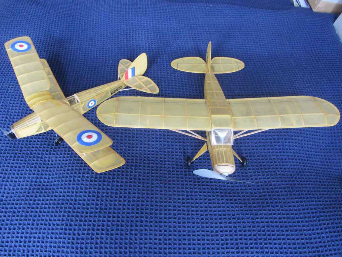
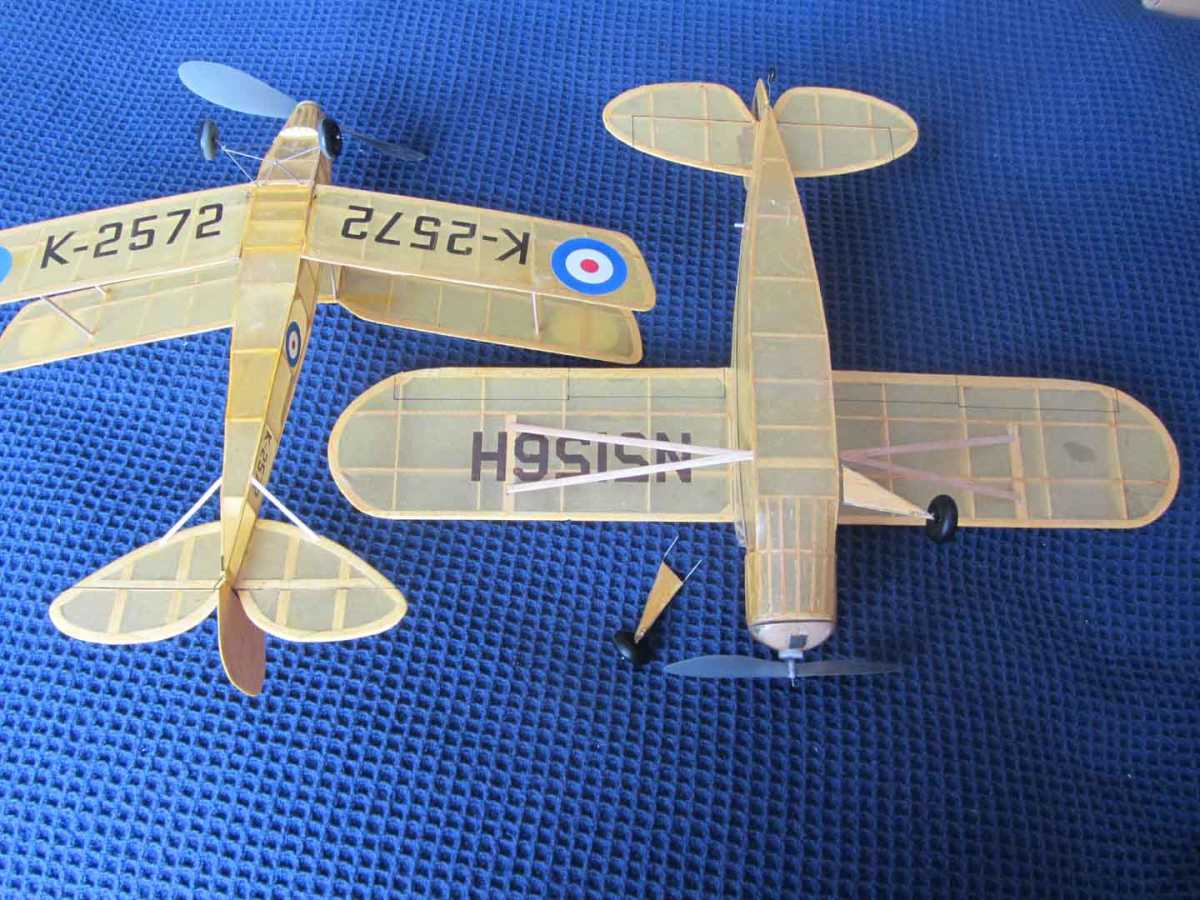
All the above are essentially outdoor free flight scale models of more than 25" wingspan. If we go smaller, the old Kiel Kraft and Veron 3/6d (or 3/9d after purchase tax took a hold) kits, then for the most part we can leave 'em in one piece. We still need to make them bounce, so light springy wood is best.
Here's a couple of photos of the Kiel Kraft Piper Family Cruiser (21" span) and the Veron Tiger Moth (18" span). Both fly well, both indoors and out and both would be suitable for lightweight radio robbed from one of the Parkzone machines for example. Both models were built within the last 5 years and both are showing signs of battle damage! Note the removable wheels on the Piper - I did that to reduce the vertical height of the model for transport/packing purposes. Both models are good for the BMFA Kit Scale competitions and SAM 35 Masefield comps.
The plans are available as downloads from Outerzone:
KK Piper Family Cruiser - www.outerzone.co.uk/plan_details.asp?ID=1361
Veron Tiger Moth - www.outerzone.co.uk/plan_details.asp?ID=779
Both of my models are finished in yellow tissue with the black markings printed directly onto the tissue (before covering) by an ink jet printer. The Tiger Moth roundels and fin flash are sprayed colour dope.
PS: for those who were not there at the time (1960 - 1969), 3/6d = 17.5p and 3/9 = 18.75p. My pocket money at the time was 10/- a week (50p) and I 'earned' £1.10.0 a week (£1.50) at a Saturday job. 3/6 in today's money would be around £6.00. SO when I see the Replikit full kits on sale at around £40 - £50 I realise we must have had a good deal in those days.
Here's a couple of photos of the Kiel Kraft Piper Family Cruiser (21" span) and the Veron Tiger Moth (18" span). Both fly well, both indoors and out and both would be suitable for lightweight radio robbed from one of the Parkzone machines for example. Both models were built within the last 5 years and both are showing signs of battle damage! Note the removable wheels on the Piper - I did that to reduce the vertical height of the model for transport/packing purposes. Both models are good for the BMFA Kit Scale competitions and SAM 35 Masefield comps.
The plans are available as downloads from Outerzone:
KK Piper Family Cruiser - www.outerzone.co.uk/plan_details.asp?ID=1361
Veron Tiger Moth - www.outerzone.co.uk/plan_details.asp?ID=779
Both of my models are finished in yellow tissue with the black markings printed directly onto the tissue (before covering) by an ink jet printer. The Tiger Moth roundels and fin flash are sprayed colour dope.
PS: for those who were not there at the time (1960 - 1969), 3/6d = 17.5p and 3/9 = 18.75p. My pocket money at the time was 10/- a week (50p) and I 'earned' £1.10.0 a week (£1.50) at a Saturday job. 3/6 in today's money would be around £6.00. SO when I see the Replikit full kits on sale at around £40 - £50 I realise we must have had a good deal in those days.
Last edit: 15 Sep 2013 10:45 by Ex-Member. Reason: added info
Please Log in or Create an account to join the conversation.
- Sarah-Jane Smith
-

- Offline
- Forum Veteran
-

- Gone
Less
More
15 Sep 2013 10:51 #10
by Sarah-Jane Smith
I wish I was a glow worm, a glow worm's never glum.
Cos how can you be grumpy when the sun shines out your bum?!
Replied by Sarah-Jane Smith on topic Fixing WIngs and U/Cs to a FF Scale Model
I used to earn £6.10 on my Saturday job growing up 
These are lovely builds Andy, thank you for sharing them.
These are lovely builds Andy, thank you for sharing them.
I wish I was a glow worm, a glow worm's never glum.
Cos how can you be grumpy when the sun shines out your bum?!
Thanks: Ex-Member
Please Log in or Create an account to join the conversation.
- Quorneng
-

- Offline
- Forum Master
-

Less
More
- Posts: 10058
- Thank you received: 19043
15 Sep 2013 20:05 #11
by Quorneng
Replied by Quorneng on topic Fixing WIngs and U/Cs to a FF Scale Model
I used to earn that sort of money for a full 48 hour week as an apprentice tool maker. The 40 hour week did not come in for several more years!
Thanks: Sarah-Jane Smith
Please Log in or Create an account to join the conversation.
- Ex-Member
- Topic Author
- Visitor
-
04 Nov 2013 11:37 - 04 Nov 2013 11:40 #12
by Ex-Member
Replied by Ex-Member on topic Fixing WIngs and U/Cs to a FF Scale Model
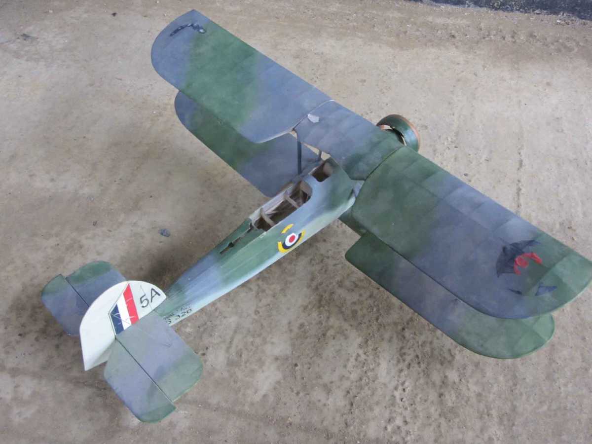
My sister wanted one of my models to decorate her sewing room, so after a search through the loft and a presentation of about 5 likely candidates, she settled on the Aerographics Fairey Swordfish. I built the model about 15 years ago as a Kit Review piece for Aeromodeller. After building and flying her, she was disassembled and stored. Generally she's fared well, but I need to do some cosmetic repairs, especially on the flaking decals, before I can hand it over to sis.
The reason for posting here is to illustrate a different but effective wing fixing method.
First a general layout pic:
Next the wing root. Note the dowel locating pins and the corresponding holes in the wing centre-section (picture taken from underside of model):

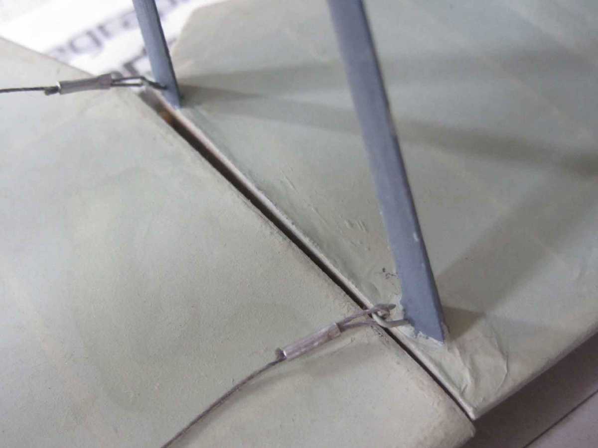
The following pic shows the interplane strut fixing and the rigging wire. The strut has been removed from the far fixing point for clarity. The strut is built up with balsa on a thin ply strip with holes in the end. The rigging wires are thick thread crimped with 1/16" dia ali tube. The hooks in the wing are 1/13" dia wire bound to the main spar:

Finally, a shot of the wing root showing the rigging wires and their 1/32" wire attachment hooks:
The reason for posting here is to illustrate a different but effective wing fixing method.
First a general layout pic:
Next the wing root. Note the dowel locating pins and the corresponding holes in the wing centre-section (picture taken from underside of model):
The following pic shows the interplane strut fixing and the rigging wire. The strut has been removed from the far fixing point for clarity. The strut is built up with balsa on a thin ply strip with holes in the end. The rigging wires are thick thread crimped with 1/16" dia ali tube. The hooks in the wing are 1/13" dia wire bound to the main spar:
Finally, a shot of the wing root showing the rigging wires and their 1/32" wire attachment hooks:
Last edit: 04 Nov 2013 11:40 by Ex-Member.
Please Log in or Create an account to join the conversation.
- Monz
-

- Offline
- Elite Member
-

17 May 2014 19:37 #13
by Monz
Replied by Monz on topic Fixing WIngs and U/Cs to a FF Scale Model
Hi Andy, I found this forum through Tony's Se5. Thanks for all these tips! It's great to see how it's actually done, especially for someone like me that is a visual learner. Can you do a thread on trimming scale models too when you have time please?
Cheers,
Monz
Cheers,
Monz
Please Log in or Create an account to join the conversation.
- Garry Pollard
- Visitor
-
17 May 2014 19:54 #14
by Garry Pollard
Replied by Garry Pollard on topic Fixing WIngs and U/Cs to a FF Scale Model
Hi Monz
Let me be the first to welcome you to Modelchat on behalf of the Admin team.
When you have a min , please feel free to put a post on the "Introduce Yourself " thread. Just a few details about yourself , where you live approx and flying experience. Then we will have some idea how to advise you
Garry Pollard
Let me be the first to welcome you to Modelchat on behalf of the Admin team.
When you have a min , please feel free to put a post on the "Introduce Yourself " thread. Just a few details about yourself , where you live approx and flying experience. Then we will have some idea how to advise you
Garry Pollard
Please Log in or Create an account to join the conversation.
- Ex-Member
- Visitor
-
17 May 2014 19:57 #15
by Ex-Member
Replied by Ex-Member on topic Fixing WIngs and U/Cs to a FF Scale Model
monz builds huge depron buccaneer gliders.
Please Log in or Create an account to join the conversation.
Time to create page: 0.271 seconds