
- Posts: 10058
- Thank you received: 19043
A Depron Airbus A350 for 50 mm EDFs - maybe?
- Quorneng
-
 Topic Author
- Offline
- Forum Master
-

Less
More
09 Oct 2017 22:42 - 09 Oct 2017 22:50 #1
by Quorneng
A Depron Airbus A350 for 50 mm EDFs - maybe? was created by Quorneng
This may not proceed very far as a build thread as I can see some good reasons why not to proceed! 
1. A conventional low wing plane with its EDFs slung under the wing does not make for a good rough field belly lander and an airliner with single 'Alsaka' wheels does not look right.
2. Compared to an 'in fuselage' EDF an under slung one requires a strong (heavy) mounting pylon that places a concentrated load into the wing.
3. The huge turbo fans on the A350 mean that even with scale nacelles the wing area is on the small side even for a lightweight EDF.
4. When sized for 50 mm EDFs the highly tapered wing means the tips are particularly narrow. They are thus likely to be prone to a serious wing drop and auto rotation at the stall.
So far I had established that the 50 mm EDF gave a reasonable representation of the exhaust of the A350's Trent turbofan..


The next step would be to 'print' the inlet duct as well. This would make the duct a self contained structural unit such that the nacelle outer profile could be just 2 mm Depron skin.
After many test pieces the complete duct.

The inlet 'ring' is printed as well.
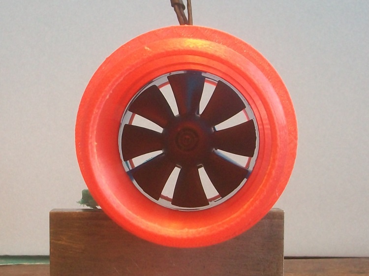
The complete duct (front and back) only adds 7.3 g to the 61 g of the bare EDF yet is remarkably stiff and strong.
The next step is to design & print the supporting pylon.
1. A conventional low wing plane with its EDFs slung under the wing does not make for a good rough field belly lander and an airliner with single 'Alsaka' wheels does not look right.
2. Compared to an 'in fuselage' EDF an under slung one requires a strong (heavy) mounting pylon that places a concentrated load into the wing.
3. The huge turbo fans on the A350 mean that even with scale nacelles the wing area is on the small side even for a lightweight EDF.
4. When sized for 50 mm EDFs the highly tapered wing means the tips are particularly narrow. They are thus likely to be prone to a serious wing drop and auto rotation at the stall.
So far I had established that the 50 mm EDF gave a reasonable representation of the exhaust of the A350's Trent turbofan..
The next step would be to 'print' the inlet duct as well. This would make the duct a self contained structural unit such that the nacelle outer profile could be just 2 mm Depron skin.
After many test pieces the complete duct.
The inlet 'ring' is printed as well.
The complete duct (front and back) only adds 7.3 g to the 61 g of the bare EDF yet is remarkably stiff and strong.
The next step is to design & print the supporting pylon.
Last edit: 09 Oct 2017 22:50 by Quorneng.
Thanks: Klipkopwildlife, THE BLACKBIRD, boz, Squirrelnet, Robbi
Please Log in or Create an account to join the conversation.
- boz
-

- Offline
- Platinum Member
-

Less
More
- Posts: 1392
- Thank you received: 1420
10 Oct 2017 05:48 #2
by boz
Replied by boz on topic A Depron Airbus A350 for 50 mm EDFs - maybe?
I'm following, looks interesting and your good at problem solving Q. 
Please Log in or Create an account to join the conversation.
- Quorneng
-
Topic Author
- Offline
- Forum Master
-
Less
More
- Posts: 10058
- Thank you received: 19043
11 Oct 2017 23:27 - 11 Oct 2017 23:29 #3
by Quorneng
Replied by Quorneng on topic A Depron Airbus A350 for 50 mm EDFs - maybe?
As I feared to make the pylon strong and rigid enough to support the EDF means it is about as heavy (5 g) as the complete nacelle duct work. Just as well the A350 has a particularly small pylon!
The Mk1 pylon temporarily glued in place with the wing position marked out

The scale pylon extends quite a bit further forward along the top of the nacelle but with my EDF so far back I don't have to so it will be simply made up with Depron.
On the final version the EDF wires will be extended and run up inside the pylon into the wing.
My intention is to complete the nacelle, with its Depron covering. and then decide if I really want to go on!
I have no idea how I would make this!

.
The Mk1 pylon temporarily glued in place with the wing position marked out
The scale pylon extends quite a bit further forward along the top of the nacelle but with my EDF so far back I don't have to so it will be simply made up with Depron.
On the final version the EDF wires will be extended and run up inside the pylon into the wing.
My intention is to complete the nacelle, with its Depron covering. and then decide if I really want to go on!
I have no idea how I would make this!
.
Last edit: 11 Oct 2017 23:29 by Quorneng.
Thanks: Klipkopwildlife, THE BLACKBIRD, boz
Please Log in or Create an account to join the conversation.
- one tenor
-

- Offline
- Forum Veteran
-

- johnpcalex@gmail.com
12 Oct 2017 00:30 #4
by one tenor
Anything will fly given enough power
Replied by one tenor on topic A Depron Airbus A350 for 50 mm EDFs - maybe?
3/4 mm Depron with 20/22/ SWG wire front and rear i.e. LE and TE perhaps
Anything will fly given enough power
Please Log in or Create an account to join the conversation.
- Quorneng
-
Topic Author
- Offline
- Forum Master
-
Less
More
- Posts: 10058
- Thank you received: 19043
14 Oct 2017 17:34 #5
by Quorneng
Replied by Quorneng on topic A Depron Airbus A350 for 50 mm EDFs - maybe?
A short test run of the completed nacelle.
In the video it is drawing 10A from my rather tired 'bench test' 2s.
It runs a bit faster (12A) on a 'good' 2s.
This is the 'better' of the two 50 mm EDFs I have and its balance is still not that good.
On the other there is significant vibration even without the fan in place and I cannot get the motor shaft to budge in order to balance the bell! 
In the video it is drawing 10A from my rather tired 'bench test' 2s.
It runs a bit faster (12A) on a 'good' 2s.
This is the 'better' of the two 50 mm EDFs I have and its balance is still not that good.
On the other there is significant vibration even without the fan in place
and I cannot get the motor shaft to budge in order to balance the bell!
Thanks: Klipkopwildlife, THE BLACKBIRD, boz, Squirrelnet
Please Log in or Create an account to join the conversation.
- Eric
-

- Offline
- Moderator
-

Less
More
- Posts: 15406
- Thank you received: 14306
15 Oct 2017 18:48 #6
by Eric
if you are calm and collected when all about you are going berserk - you've missed something important!
Replied by Eric on topic A Depron Airbus A350 for 50 mm EDFs - maybe?
IF (big if!) you can work out which is the heavy side, add layers of paint to the light side to see if that helps - use a very dense colour, as that is heavier than a light one (IYSWIM!) 
if you are calm and collected when all about you are going berserk - you've missed something important!
Please Log in or Create an account to join the conversation.
- Quorneng
-
Topic Author
- Offline
- Forum Master
-
Less
More
- Posts: 10058
- Thank you received: 19043
16 Oct 2017 17:22 #7
by Quorneng
Replied by Quorneng on topic A Depron Airbus A350 for 50 mm EDFs - maybe?
Yes indeed.
I have already done that on the good EDF to balance the fan (I can just get it on my magnetic balance) as the motor alone was in good balance.
The other EDF is problem as the motor itself is out of balance and as its shaft will not move (I fear it is 'lock tighted' in) I have no way of mounting it in the balancer.
After a bit of trial and error I can now print both the inner and outer surfaces of the nacelle in a single piece with only a small weight penalty although to physically get the EDF in it would have to be split in some way.

The problem is it has to be a 'regular' shape with a constant outer curvature. Unfortunately the Trent nacelle outer skin is 'offset'. In other words it thicker on the top than underneath and so far I have not found a way of generating such a shape in FreeCad.
I suspect I might have to use 'Blender' and create it as a mesh?
I have already done that on the good EDF to balance the fan (I can just get it on my magnetic balance) as the motor alone was in good balance.
The other EDF is problem as the motor itself is out of balance and as its shaft will not move (I fear it is 'lock tighted' in) I have no way of mounting it in the balancer.
After a bit of trial and error I can now print both the inner and outer surfaces of the nacelle in a single piece with only a small weight penalty although to physically get the EDF in it would have to be split in some way.
The problem is it has to be a 'regular' shape with a constant outer curvature. Unfortunately the Trent nacelle outer skin is 'offset'. In other words it thicker on the top than underneath and so far I have not found a way of generating such a shape in FreeCad.
I suspect I might have to use 'Blender' and create it as a mesh?
Thanks: Klipkopwildlife, THE BLACKBIRD, boz, Squirrelnet
Please Log in or Create an account to join the conversation.
- one tenor
-
- Offline
- Forum Veteran
-
- johnpcalex@gmail.com
17 Oct 2017 15:59 #8
by one tenor
Anything will fly given enough power
Replied by one tenor on topic A Depron Airbus A350 for 50 mm EDFs - maybe?
If you use what appears to be a seam underneath as a joint line the shell may spring enough to allow the gubbins in. Just a thought.Otherwise I would go for a circumfrentional cut. Just MHO Nice work though. Tin he shaft may yield to heat and a tube spacer on a vice. FWIW
Anything will fly given enough power
Please Log in or Create an account to join the conversation.
- Quorneng
-
Topic Author
- Offline
- Forum Master
-
Less
More
- Posts: 10058
- Thank you received: 19043
17 Oct 2017 23:38 #9
by Quorneng
Replied by Quorneng on topic A Depron Airbus A350 for 50 mm EDFs - maybe?
On the basis that the EDF was so out of balance as to be useless the shaft was eventually removed with the aid of tubular spacers and a vice.
The fan proved to be seriously out of balance requiring several coats of clear lacquer and three layers of masking tape on the inside of the hub!
The motor bell was not that bad requiring just a couple of blobs of glue between the magnets however the big issue was the shaft did not run true!
Set up in the lathe with a DTI I managed to get the run out to less than a 'thou'.
Still not prefect but its now at least as good as the first EDF.
Moral? Don't expect too much from cheap EDFs. .
The fan proved to be seriously out of balance requiring several coats of clear lacquer and three layers of masking tape on the inside of the hub!
The motor bell was not that bad requiring just a couple of blobs of glue between the magnets however the big issue was the shaft did not run true!
Set up in the lathe with a DTI I managed to get the run out to less than a 'thou'.
Still not prefect but its now at least as good as the first EDF.
Moral? Don't expect too much from cheap EDFs.
.
Thanks: boz
Please Log in or Create an account to join the conversation.
- one tenor
-
- Offline
- Forum Veteran
-
- johnpcalex@gmail.com
18 Oct 2017 14:51 #10
by one tenor
Anything will fly given enough power
Replied by one tenor on topic A Depron Airbus A350 for 50 mm EDFs - maybe?
Well done Q I'm glad my tip helped.I would be onto the supplier for a new motor .I'd notify them anyway. The pic is like the real thing.Well done
Anything will fly given enough power
Please Log in or Create an account to join the conversation.
- Quorneng
-
Topic Author
- Offline
- Forum Master
-
Less
More
- Posts: 10058
- Thank you received: 19043
18 Oct 2017 23:02 #11
by Quorneng
Replied by Quorneng on topic A Depron Airbus A350 for 50 mm EDFs - maybe?
After spending far too much time on it I have completed an .all printed. nacelle.
Although it is a single "stl file" it is printed in two parts by the simple method of carefully 'submerging' it exactly the right amount below the bed surface first one way up then the other.. This ensures the two halves exactly match to give a sooth continuous surface when glued together. .

The two halves temporarily glued with the EDF in place.

The complete nacelle and pylon weighs 19.9 g. The EDF with its bell mouth cut off weighs 55 g.
Overall the printed outer skin adds about 8 g over the Depron skin version.
Although it takes nearly 3 hours to print both bits overall this is significantly quicker when the time taken to Depron plank is included and it is of course exactly reproducible!
The outer profile of the nacelle is still not quite right but not worth adjusting at this stage until the pylon/wing attachment method is sorted out and that will require the wing to be designed and built, all of which assumes I decide to proceed! . .
. .
.
Although it is a single "stl file" it is printed in two parts by the simple method of carefully 'submerging' it exactly the right amount below the bed surface first one way up then the other.. This ensures the two halves exactly match to give a sooth continuous surface when glued together. .
The two halves temporarily glued with the EDF in place.
The complete nacelle and pylon weighs 19.9 g. The EDF with its bell mouth cut off weighs 55 g.
Overall the printed outer skin adds about 8 g over the Depron skin version.
Although it takes nearly 3 hours to print both bits overall this is significantly quicker when the time taken to Depron plank is included and it is of course exactly reproducible!
The outer profile of the nacelle is still not quite right but not worth adjusting at this stage until the pylon/wing attachment method is sorted out and that will require the wing to be designed and built, all of which assumes I decide to proceed!
. ..
Thanks: Klipkopwildlife, THE BLACKBIRD, Squirrelnet
Please Log in or Create an account to join the conversation.
- boz
-
- Offline
- Platinum Member
-
Less
More
- Posts: 1392
- Thank you received: 1420
19 Oct 2017 07:02 #12
by boz
Replied by boz on topic A Depron Airbus A350 for 50 mm EDFs - maybe?
Lovely work Q,
Proceed? Yes please do, very interesting thread.
Proceed? Yes please do, very interesting thread.
Please Log in or Create an account to join the conversation.
- Quorneng
-
Topic Author
- Offline
- Forum Master
-
Less
More
- Posts: 10058
- Thank you received: 19043
19 Oct 2017 14:17 - 19 Oct 2017 14:19 #13
by Quorneng
Replied by Quorneng on topic A Depron Airbus A350 for 50 mm EDFs - maybe?
Now comes the problem bit.
This drawing has been 'tidied up' a bit from a 3 view.
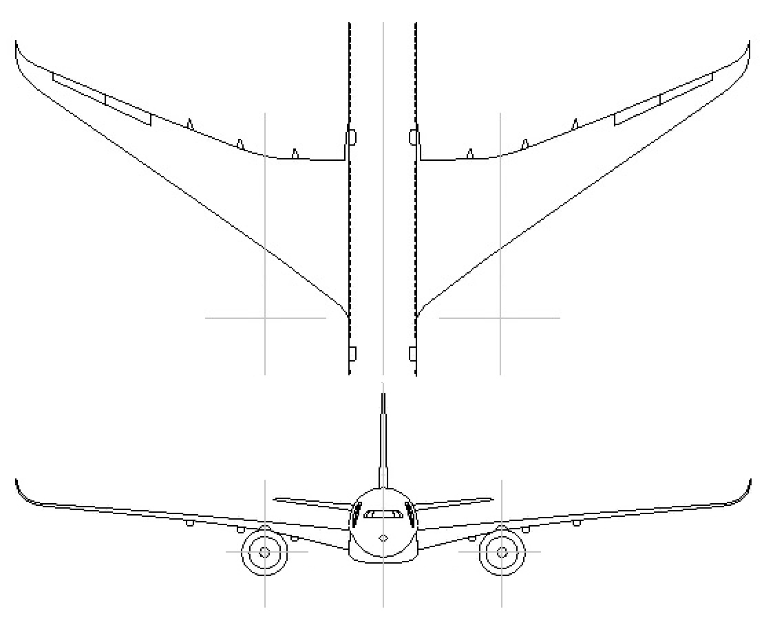
When the nacelle is sized to encompass a 50 mm EDF the span comes out at 48" (1200 mm). That may sound reasonable for a twin small EDF plane but the A350 wing is very tapered. Even before the 'curly' tip section the wing chord is only 2" (50 mm) and I have found that wing chords below 3" (75 mm) not only tend to be rather inefficient but have a nasty tendency to 'spiral in' anywhere near the stall. Substantial washout helps but that would further reduces the effectiveness of what is already a rather small area wing (less than 1 sq ft!) for a plane with a 'guesstimated' all up weight close to 25 oz (700 g).
To keep to the simple hand launch concept either the size has to up or the weight has to come down or both!
I do have some ideas.
This drawing has been 'tidied up' a bit from a 3 view.
When the nacelle is sized to encompass a 50 mm EDF the span comes out at 48" (1200 mm). That may sound reasonable for a twin small EDF plane but the A350 wing is very tapered. Even before the 'curly' tip section the wing chord is only 2" (50 mm) and I have found that wing chords below 3" (75 mm) not only tend to be rather inefficient but have a nasty tendency to 'spiral in' anywhere near the stall. Substantial washout helps but that would further reduces the effectiveness of what is already a rather small area wing (less than 1 sq ft!) for a plane with a 'guesstimated' all up weight close to 25 oz (700 g).
To keep to the simple hand launch concept either the size has to up or the weight has to come down or both!
I do have some ideas.
Last edit: 19 Oct 2017 14:19 by Quorneng.
Thanks: Eric, Klipkopwildlife, THE BLACKBIRD, boz
Please Log in or Create an account to join the conversation.
- Quorneng
-
Topic Author
- Offline
- Forum Master
-
Less
More
- Posts: 10058
- Thank you received: 19043
20 Oct 2017 01:48 #14
by Quorneng
Replied by Quorneng on topic A Depron Airbus A350 for 50 mm EDFs - maybe?
By far the biggest benefit of 3d printing is the ability to reproduce exact multiple copies of anything.
With a thin 2mm Depron skin the long parallel section of the A350 fuselage is going to need many fuselage formers - all the same.
This shows a fuselage former compared to the Trent nacelle.
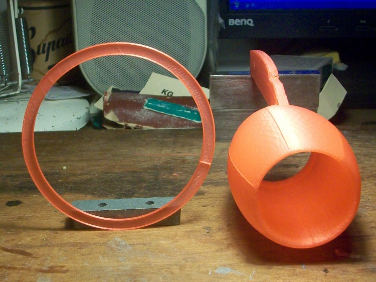
Its not that the fuselage of the A350 is small (it seats 9 abreast) but rather just how big the Trent is!
The printed "U" channel former weighs exactly 1 g yet is as stiff as a 2 mm Depron 'ring' former of nearly twice the depth.
Still thinking.
With a thin 2mm Depron skin the long parallel section of the A350 fuselage is going to need many fuselage formers - all the same.
This shows a fuselage former compared to the Trent nacelle.
Its not that the fuselage of the A350 is small (it seats 9 abreast) but rather just how big the Trent is!
The printed "U" channel former weighs exactly 1 g yet is as stiff as a 2 mm Depron 'ring' former of nearly twice the depth.
Still thinking.
Thanks: Klipkopwildlife, THE BLACKBIRD, boz
Please Log in or Create an account to join the conversation.
- Quorneng
-
Topic Author
- Offline
- Forum Master
-
Less
More
- Posts: 10058
- Thank you received: 19043
21 Oct 2017 00:57 #15
by Quorneng
Replied by Quorneng on topic A Depron Airbus A350 for 50 mm EDFs - maybe?
Grandson's 6th birthday today so I finally got the opportunity to play with remote control Lego train set that I gave him.
Dual controller with 4 selectable channels so you can control 8 different locos. Even the wiring connectors look like bricks and just press together!
Thinking about the fuselage formers I spent an hour or so drawing out a possible fuselage plan.

With a 2" spacing there would be a lot of them!
I had not appreciated how 'wasted' the fuselage is around the tail plane, presumable to allow for the all moving tail plane.
Dual controller with 4 selectable channels so you can control 8 different locos. Even the wiring connectors look like bricks and just press together!
Thinking about the fuselage formers I spent an hour or so drawing out a possible fuselage plan.
With a 2" spacing there would be a lot of them!
I had not appreciated how 'wasted' the fuselage is around the tail plane, presumable to allow for the all moving tail plane.
Thanks: Eric, Klipkopwildlife, THE BLACKBIRD, boz
Please Log in or Create an account to join the conversation.
Time to create page: 0.259 seconds