
- Posts: 10058
- Thank you received: 19043
Hawker Sea Hawk
- Quorneng
-
 Topic Author
- Offline
- Forum Master
-

Less
More
06 May 2021 22:28 #1
by Quorneng
Hawker Sea Hawk was created by Quorneng
I said I wanted to build an F4D Sky Ray however on further examination the 55 mm EDF I have salvaged would give a way undersize tail pipe for the scale I had imagined so the obvious solution would be an 'early' jet as they had small tail pipes and most had straight wings. The Sea Hawk fit this bill neatly.

The other advantage that came to mind with both its inlets and exhausts bifurcated was that it might be possible to print the complete inlry and exhaust duct so when fixed to the EDF it would be come a 'stand alone unit' and with little weight penalty. The rest of the airframe would be just built around it.
Some sums showed that with each of the twin nozzles at 28 mm diameter would give a total area equal to 85% of the 55 mm fan's FSA.
This set the scale of the Sea Hawk!
It would have a span of some 45", so plenty big enough.
The exhaust nozzles would be 140 mm between centres so a 1/2 size test duct.

You can see why in the factory the exhaust duct were referred to as 'the trousers'.
Next quite a bit a adjustment of the CAD file to give exactly the right overall dimensions.
The other advantage that came to mind with both its inlets and exhausts bifurcated was that it might be possible to print the complete inlry and exhaust duct so when fixed to the EDF it would be come a 'stand alone unit' and with little weight penalty. The rest of the airframe would be just built around it.
Some sums showed that with each of the twin nozzles at 28 mm diameter would give a total area equal to 85% of the 55 mm fan's FSA.
This set the scale of the Sea Hawk!
It would have a span of some 45", so plenty big enough.
The exhaust nozzles would be 140 mm between centres so a 1/2 size test duct.
You can see why in the factory the exhaust duct were referred to as 'the trousers'.
Next quite a bit a adjustment of the CAD file to give exactly the right overall dimensions.
Attachments:
Thanks: Eric, Klipkopwildlife, Flytilbroke, THE BLACKBIRD, Ralpharr2001, paul d, crash happy
Please Log in or Create an account to join the conversation.
- Quorneng
-
Topic Author
- Offline
- Forum Master
-
Less
More
- Posts: 10058
- Thank you received: 19043
07 May 2021 21:26 - 07 May 2021 21:26 #2
by Quorneng
Replied by Quorneng on topic Hawker Sea Hawk
Took the best part of a day to get a print to work but there are now a set of 'big' trousers.

The trousers weigh 13.5 g
I eventually had to print them is 3 pieces as the print head would tend to just catch the print when traveling between the trouser legs. No problem one way as the print would simply flex but on the return if it touched it simply lifted it off the bed.
To make matters worse it took nearly an hour printing before the problem ever arose. After 2 failures I decided to print the legs individually.
The inlet half of the duct is proving to be rather harder as it has to go from 2 triangles to a circle. Fiddly when done with Depron planks but a smooth double curve change in section was at least possible.
The trousers weigh 13.5 g
I eventually had to print them is 3 pieces as the print head would tend to just catch the print when traveling between the trouser legs. No problem one way as the print would simply flex but on the return if it touched it simply lifted it off the bed.
To make matters worse it took nearly an hour printing before the problem ever arose. After 2 failures I decided to print the legs individually.
The inlet half of the duct is proving to be rather harder as it has to go from 2 triangles to a circle. Fiddly when done with Depron planks but a smooth double curve change in section was at least possible.
Attachments:
Last edit: 07 May 2021 21:26 by Quorneng.
Thanks: Eric, Klipkopwildlife, crash happy
Please Log in or Create an account to join the conversation.
- Eric
-

- Offline
- Moderator
-

Less
More
- Posts: 15406
- Thank you received: 14305
07 May 2021 22:11 #3
by Eric
if you are calm and collected when all about you are going berserk - you've missed something important!
Replied by Eric on topic Hawker Sea Hawk
Sea Hawk - pretty aeroplane - I never saw a 12" to the foot one. They'd been replaced by the Vixen, when I was 'in'.
if you are calm and collected when all about you are going berserk - you've missed something important!
Thanks: Klipkopwildlife
Please Log in or Create an account to join the conversation.
- Quorneng
-
Topic Author
- Offline
- Forum Master
-
Less
More
- Posts: 10058
- Thank you received: 19043
08 May 2021 21:16 #4
by Quorneng
Replied by Quorneng on topic Hawker Sea Hawk
Another whole day spent printing, or rather getting the printing to work but eventually something like right.
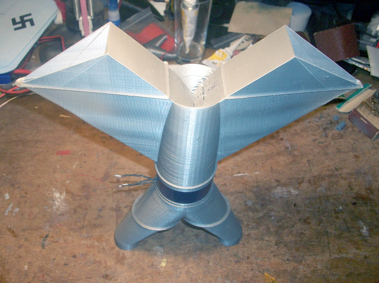
By comparison the EDF looks tiny!
The complete duct weighs 36.8 g. The EDF weighs 63.3 g so the complete assembly weighs 100.1 g.
For a 55 mm EDF on 3s it will be quite a big plane with a span of 43".
By comparison the EDF looks tiny!
The complete duct weighs 36.8 g. The EDF weighs 63.3 g so the complete assembly weighs 100.1 g.
For a 55 mm EDF on 3s it will be quite a big plane with a span of 43".
Attachments:
Thanks: Klipkopwildlife, crash happy
Please Log in or Create an account to join the conversation.
- Klipkopwildlife
-

- Offline
- Administrator
-

- I'm supposed to be retired!
09 May 2021 08:11 #5
by Klipkopwildlife
Do it now, you may never get another chance
Replied by Klipkopwildlife on topic Hawker Sea Hawk
Really showing what 3D printing can do, I remember how you've battled in the past to get decent shapes using ordinary materials.
Do it now, you may never get another chance
Please Log in or Create an account to join the conversation.
- Quorneng
-
Topic Author
- Offline
- Forum Master
-
Less
More
- Posts: 10058
- Thank you received: 19043
09 May 2021 14:41 - 09 May 2021 14:43 #6
by Quorneng
Replied by Quorneng on topic Hawker Sea Hawk
The next task is to make sure the complete duct assembly will actual fit in the proposed airframe. It has to fit pretty accurately at four points, at both the inlets and exhausts.

It looks to be an acceptable fit.
As the EDF has a 'straight through' airflow which with a bifurcated arrangement tends to result in the EDF being midway between the inlet and exhaust to give something like equal duct losses.
The double sided centrifugal compressor on the Nene had a very tortuous inlet path so it could be placed further forward with little loss in inlet performance but some benefit to the exhaust. This resulted in the jet was placed at about the point of the wing spar which gave a convenient strong mounting.
As on my Sea Hawk the EDF is ay the mid point it means the spar will be well ahead of it and have to go round the very fragile inlet duct. The spar will provide no direct support to the EDF.
Maybe I should consider moving the EDF forward, suffer any loss in the efficiency of the inlet path and simply copy the Sea Hawk's 16 pressure relief flaps (cheat holes?) on the top of the fuselage!
One advantage of 'playing' with CAD is it costs nothing but time to experiment!
We shall see.
It looks to be an acceptable fit.
As the EDF has a 'straight through' airflow which with a bifurcated arrangement tends to result in the EDF being midway between the inlet and exhaust to give something like equal duct losses.
The double sided centrifugal compressor on the Nene had a very tortuous inlet path so it could be placed further forward with little loss in inlet performance but some benefit to the exhaust. This resulted in the jet was placed at about the point of the wing spar which gave a convenient strong mounting.
As on my Sea Hawk the EDF is ay the mid point it means the spar will be well ahead of it and have to go round the very fragile inlet duct. The spar will provide no direct support to the EDF.
Maybe I should consider moving the EDF forward, suffer any loss in the efficiency of the inlet path and simply copy the Sea Hawk's 16 pressure relief flaps (cheat holes?) on the top of the fuselage!
One advantage of 'playing' with CAD is it costs nothing but time to experiment!
We shall see.
Attachments:
Last edit: 09 May 2021 14:43 by Quorneng.
Thanks: Eric, Klipkopwildlife, Flytilbroke, Ralpharr2001, crash happy
Please Log in or Create an account to join the conversation.
- Ralpharr2001
-

- Offline
- Elite Member
-

Less
More
- Posts: 524
- Thank you received: 1476
09 May 2021 16:29 #7
by Ralpharr2001
I'm currently unsupervised. I know it freaks me out as well, but the possibilities are endless!!
Replied by Ralpharr2001 on topic Hawker Sea Hawk
Very impressive work Q.
I'm currently unsupervised. I know it freaks me out as well, but the possibilities are endless!!
Thanks: Klipkopwildlife
Please Log in or Create an account to join the conversation.
- Quorneng
-
Topic Author
- Offline
- Forum Master
-
Less
More
- Posts: 10058
- Thank you received: 19043
10 May 2021 23:13 - 10 May 2021 23:14 #8
by Quorneng
Replied by Quorneng on topic Hawker Sea Hawk
I have been working on the plans today. No drawing them exactly but clearing the blobs and thin the line resulting from blown up the 3 view by a factor of nearly ten.
I did print a nose view to check the dimension of the intakes but it does rather show why I suggested it was a tiny EDF for the size of the plane.
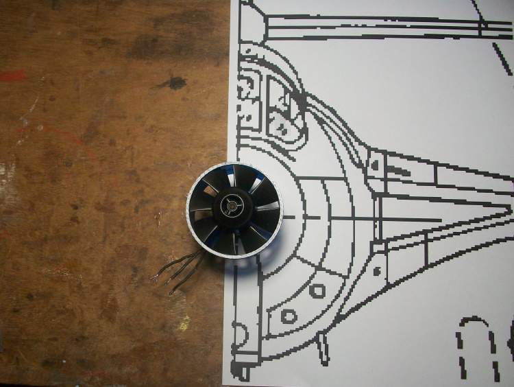
At least the scale intakes have a bigger area than the FSA.
I did print a nose view to check the dimension of the intakes but it does rather show why I suggested it was a tiny EDF for the size of the plane.
At least the scale intakes have a bigger area than the FSA.
Attachments:
Last edit: 10 May 2021 23:14 by Quorneng.
Thanks: Klipkopwildlife, crash happy
Please Log in or Create an account to join the conversation.
- Quorneng
-
Topic Author
- Offline
- Forum Master
-
Less
More
- Posts: 10058
- Thank you received: 19043
11 May 2021 16:27 - 11 May 2021 16:31 #9
by Quorneng
Replied by Quorneng on topic Hawker Sea Hawk
My first inlet duct had the inlet 'triangles' symmetrical' In fact the intakes in the Sea Hawk are not as they follow the wing dihedral coupled with the fact that the wing fairing is not symmetrical either. There is more fairing underneath than on top.
So the duct had to be modified to suit and reprinted which means about 5 hours! Drat and double drat.
Rather than just reprint the first design I elected to use a more compact arrangement that would position the EDF at the wing spar.
The first and second inlet ducts.
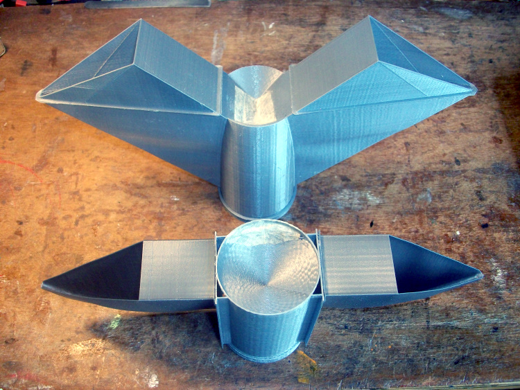
Although the more compact and shorter inlet (by 65 mm!) would possibly be less efficient the extra length after the EDF might allow a more efficient exhaust duct, however after the experience with the He 162 I am a bit nervous of inlet restrictions.
These shows the different geometry.
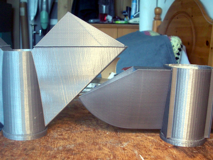
The actual inlet areas are the same. The longer one turns the air through 45 degrees, the other turns some of it through 90 degrees before it enters what is almost a plenum chamber.
No full power running yet but as far as I can tell both designs have about the same effect on the EDF compared to running without.
On that basis I would be rather happier to have the spar surround the EDF as it would give it support, it is a simple circle and is far less delicate than the duct.
I think the next step is to design & build the centre section of the wing spar, although it may end up just being a foam shear web, and then build the centre portion of the fuselage around it so 'burying' the EDF and the duct.
The rest of the airframe will then just be glued on.
So the duct had to be modified to suit and reprinted which means about 5 hours! Drat and double drat.
Rather than just reprint the first design I elected to use a more compact arrangement that would position the EDF at the wing spar.
The first and second inlet ducts.
Although the more compact and shorter inlet (by 65 mm!) would possibly be less efficient the extra length after the EDF might allow a more efficient exhaust duct, however after the experience with the He 162 I am a bit nervous of inlet restrictions.
These shows the different geometry.
The actual inlet areas are the same. The longer one turns the air through 45 degrees, the other turns some of it through 90 degrees before it enters what is almost a plenum chamber.
No full power running yet but as far as I can tell both designs have about the same effect on the EDF compared to running without.
On that basis I would be rather happier to have the spar surround the EDF as it would give it support, it is a simple circle and is far less delicate than the duct.
I think the next step is to design & build the centre section of the wing spar, although it may end up just being a foam shear web, and then build the centre portion of the fuselage around it so 'burying' the EDF and the duct.
The rest of the airframe will then just be glued on.
Attachments:
Last edit: 11 May 2021 16:31 by Quorneng.
Thanks: Klipkopwildlife, Flytilbroke, crash happy
Please Log in or Create an account to join the conversation.
- Quorneng
-
Topic Author
- Offline
- Forum Master
-
Less
More
- Posts: 10058
- Thank you received: 19043
12 May 2021 14:44 #10
by Quorneng
Replied by Quorneng on topic Hawker Sea Hawk
I decided to proceed with the shorter inlet duct and print a longer set of trousers to match but not all prints work first time.

Eventually got it all to work so the complete new set of ducts over the wing root plan.

Note the EDF is now exactly over the spar line.
The duct and EDF are now glued together so a nose down thrust test is possible.

On a storage level 3s it generated 310 g thrust and more to the point the thrust continued to increased right up to full power. This suggests the extra volt of a fully charged battery should generate still more thrust.
Just out of interest the total weight of the complete duct along with the ESC and the intended 1800 mAh 3s is just under 300g so provided the bare airframe is no more than 250 g? it should fly well enough although I would be happier if it could be made in true 2mm Depron.
The fuselage centre section incorporating the wing roots out to the wing fold line will be next.
Eventually got it all to work so the complete new set of ducts over the wing root plan.
Note the EDF is now exactly over the spar line.
The duct and EDF are now glued together so a nose down thrust test is possible.
On a storage level 3s it generated 310 g thrust and more to the point the thrust continued to increased right up to full power. This suggests the extra volt of a fully charged battery should generate still more thrust.
Just out of interest the total weight of the complete duct along with the ESC and the intended 1800 mAh 3s is just under 300g so provided the bare airframe is no more than 250 g? it should fly well enough although I would be happier if it could be made in true 2mm Depron.
The fuselage centre section incorporating the wing roots out to the wing fold line will be next.
Attachments:
Thanks: Eric, Klipkopwildlife, Flytilbroke, Ralpharr2001, crash happy
Please Log in or Create an account to join the conversation.
- Quorneng
-
Topic Author
- Offline
- Forum Master
-
Less
More
- Posts: 10058
- Thank you received: 19043
13 May 2021 21:24 #11
by Quorneng
Replied by Quorneng on topic Hawker Sea Hawk
Just because a short video of printing part of the long exhaust trouser.
Made a start on the fuselage centre section.

My usual planked stressed skin half shell over the plan style but rather harder with 5 mm foam sheets.
We shall see.
Made a start on the fuselage centre section.
My usual planked stressed skin half shell over the plan style but rather harder with 5 mm foam sheets.
We shall see.
Attachments:
Thanks: Klipkopwildlife, Ralpharr2001, paul d
Please Log in or Create an account to join the conversation.
- Quorneng
-
Topic Author
- Offline
- Forum Master
-
Less
More
- Posts: 10058
- Thank you received: 19043
14 May 2021 22:28 #12
by Quorneng
Replied by Quorneng on topic Hawker Sea Hawk
With a few more planks on it was rigid enough to be lifted from the plan. Then the fun part starts, trying to get the duct assembly to fit.
One advantage of the very soft underlay foam is it is easy to trim and just as easy to glue extra bits back on!
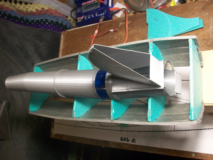
Obviously had to make sure it sat along the centre line of the duct.
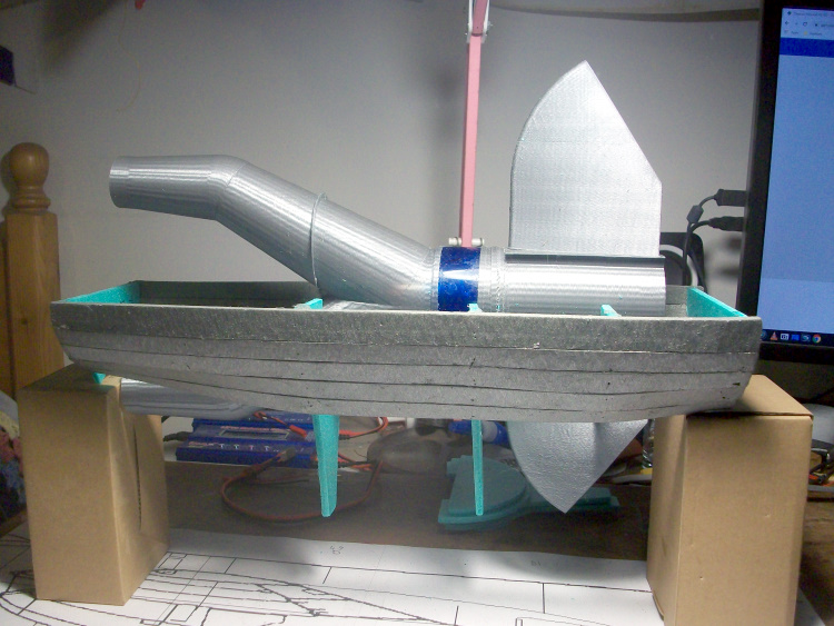
So far so good.
Next is to add & fit the other half of the formers. They were cut out as a pair with the first set but will need the same adjustment.
One advantage of the very soft underlay foam is it is easy to trim and just as easy to glue extra bits back on!
Obviously had to make sure it sat along the centre line of the duct.
So far so good.
Next is to add & fit the other half of the formers. They were cut out as a pair with the first set but will need the same adjustment.
Attachments:
Thanks: Klipkopwildlife, THE BLACKBIRD
Please Log in or Create an account to join the conversation.
- Quorneng
-
Topic Author
- Offline
- Forum Master
-
Less
More
- Posts: 10058
- Thank you received: 19043
16 May 2021 00:19 - 16 May 2021 00:20 #13
by Quorneng
Replied by Quorneng on topic Hawker Sea Hawk
Spent virtually all day slowly covering the fuselage centre section.
The LH root fairing.
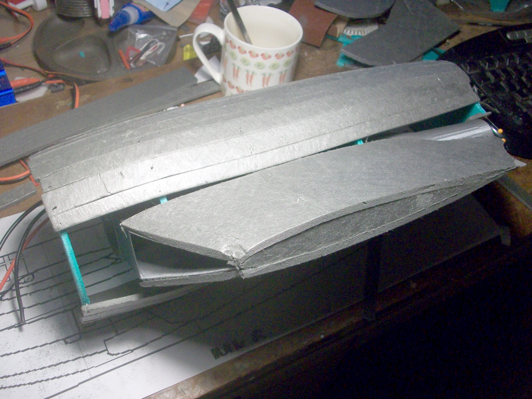
Note the motor wires are now extended. The ESC with an exposed heatsink will be placed in the cockpit wall just ahead of the RH inlet.
I can complete the upper skin but will have to leave access underneath to run the aileron and elevator servos wires.
The LH root fairing.
Note the motor wires are now extended. The ESC with an exposed heatsink will be placed in the cockpit wall just ahead of the RH inlet.
I can complete the upper skin but will have to leave access underneath to run the aileron and elevator servos wires.
Attachments:
Last edit: 16 May 2021 00:20 by Quorneng.
Thanks: Klipkopwildlife, THE BLACKBIRD, Ralpharr2001
Please Log in or Create an account to join the conversation.
- Quorneng
-
Topic Author
- Offline
- Forum Master
-
Less
More
- Posts: 10058
- Thank you received: 19043
16 May 2021 22:58 #14
by Quorneng
Replied by Quorneng on topic Hawker Sea Hawk
Quite a bit more fiddley planking.


The other side is not quite so far advanced. That's for tomorrow.
Then some filler and light sanding. It will be interesting to see what sort of surface this soft foam ends up with.
I am not over enamoured when planking in 3 and 2 mm Depron but working with this 5 mm stuff is a bit of a nightmare.
The other side is not quite so far advanced. That's for tomorrow.
Then some filler and light sanding. It will be interesting to see what sort of surface this soft foam ends up with.
I am not over enamoured when planking in 3 and 2 mm Depron but working with this 5 mm stuff is a bit of a nightmare.
Attachments:
Thanks: Klipkopwildlife, THE BLACKBIRD
Please Log in or Create an account to join the conversation.
- paul d
-
- Offline
- Forum Veteran
-

Less
More
- Posts: 2074
- Thank you received: 2292
17 May 2021 07:09 #15
by paul d
balsa is best.
Replied by paul d on topic Hawker Sea Hawk
That foam looks very soft, looking good though.
balsa is best.
Thanks: Klipkopwildlife
Please Log in or Create an account to join the conversation.
Time to create page: 0.422 seconds