
Reducing servo throw
- Klipkopwildlife
-
 Topic Author
- Offline
- Administrator
-

- I'm supposed to be retired!
I need all 9 channels!
Anybody any ideas? Is there an after market product that I can use?
Do it now, you may never get another chance
Please Log in or Create an account to join the conversation.
- Eric
-

- Offline
- Moderator
-

- Posts: 15406
- Thank you received: 14306
The two ranges quoted for the gadget (you don't say what it is) might just be the switching limits, and it will happily take less and more pulsewidth.
if you are calm and collected when all about you are going berserk - you've missed something important!
Please Log in or Create an account to join the conversation.
- Klipkopwildlife
-
Topic Author
- Offline
- Administrator
-
- I'm supposed to be retired!
Since this aircraft is to be used for Game counting by inexperienced persons, and I expect this aircraft to be frequently Out Of Sight, Stabilised flight is quite necessary, Fixed altitude is warned against in the manual since if you lose power for any reason the FY-21AP will stall the aircraft into the ground!
Do it now, you may never get another chance
Please Log in or Create an account to join the conversation.
- Eric
-
- Offline
- Moderator
-
- Posts: 15406
- Thank you received: 14306
Off the top of my head, i don't know of any solution - (see my PM) - so I'll shut up and see if anyone else has any ideas.
if you are calm and collected when all about you are going berserk - you've missed something important!
Please Log in or Create an account to join the conversation.
- Phil Wood
-

- Offline
- Inactivated User
-

You'd have to do a little modification to the Tx but it's quite easy.
On the switch you'd have to solder a couple of small resistors or a preset pot ... so that the switch will then flick between servo center & one end point.
Try to post a pic of the insides (close up of the switch) ... & I'll edit the pic to show you what's needed.
You could even change the switch for a pot & have all channels proportional.

Pol.
I just own the forum .... you guys make it great thanks.
Please Log in or Create an account to join the conversation.
- Eric
-
- Offline
- Moderator
-
- Posts: 15406
- Thank you received: 14306
 should have thought of that !
 if you are calm and collected when all about you are going berserk - you've missed something important!
Please Log in or Create an account to join the conversation.
- Klipkopwildlife
-
Topic Author
- Offline
- Administrator
-
- I'm supposed to be retired!
Do it now, you may never get another chance
Please Log in or Create an account to join the conversation.
- Klipkopwildlife
-
Topic Author
- Offline
- Administrator
-
- I'm supposed to be retired!
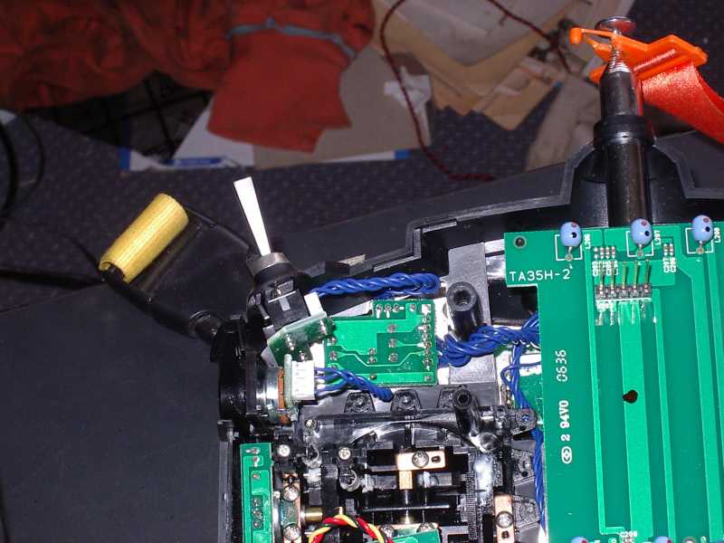
That's just with the back off
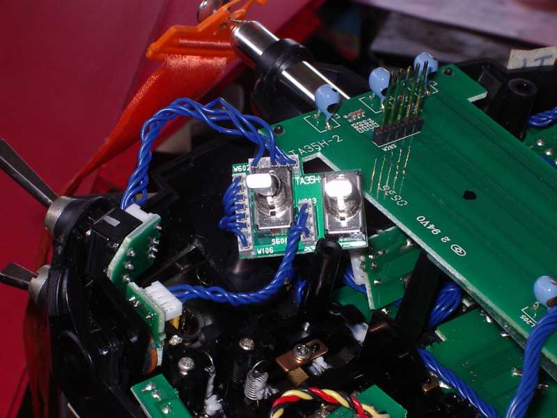
Two of the switches out and turned around
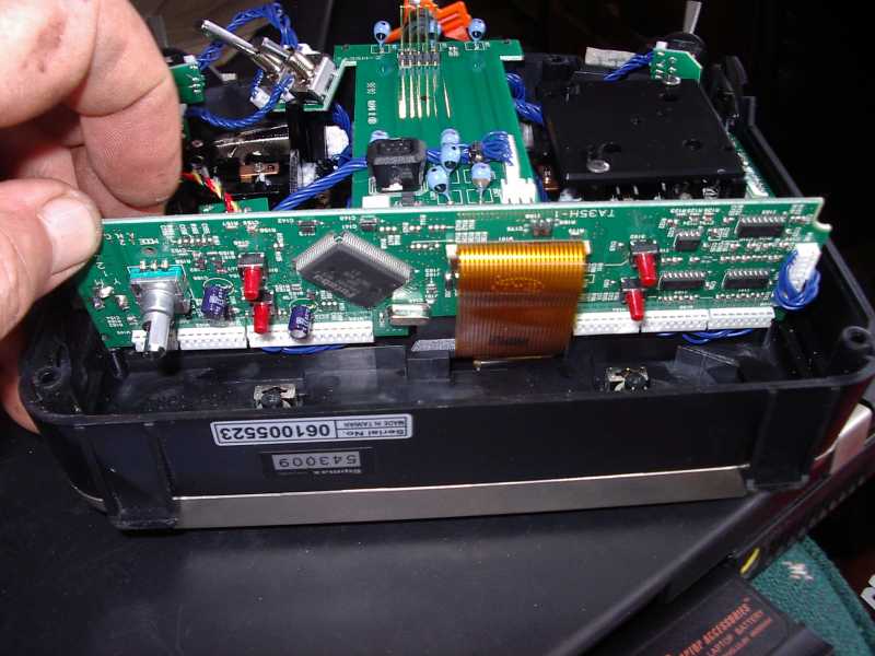
Here I've released the PC board, you can see all inputs have a diode feeder.
Do it now, you may never get another chance
Please Log in or Create an account to join the conversation.
- Klipkopwildlife
-
Topic Author
- Offline
- Administrator
-
- I'm supposed to be retired!
Do it now, you may never get another chance
Please Log in or Create an account to join the conversation.
- Eric
-
- Offline
- Moderator
-
- Posts: 15406
- Thank you received: 14306
if you are calm and collected when all about you are going berserk - you've missed something important!
Please Log in or Create an account to join the conversation.
- Klipkopwildlife
-
Topic Author
- Offline
- Administrator
-
- I'm supposed to be retired!
Do it now, you may never get another chance
Please Log in or Create an account to join the conversation.
- Phil Wood
-
- Offline
- Inactivated User
-
Klipkopwildlife wrote: It would appear that the switches are bussed direct to the main computer, there appear to be no on board resistors, except the pots for the continuously variable channels. These are called VRa through VRe and can be assigned to channels 5 through 8, but not 9! The switches (SWa through SWg, 4 on/off and 2 off/half/full) can be assigned to channels 5 through 9. But, here's the rub, if I assign a 3 position to channels 5 through 8 I get off/half/full, but assigning a 3 position to channel 9 gives me off/full/full
Bear with me on this one Klippy, you know I'm not up to full speed after my heart op' yet but I'll give it my best shot.
The general industry accepted standard in the RC world is that a 1.5 millisecond pulse will correspond with servo dead center.
The Tx sends out a series of these pulses followed by a synchronizing pulse that re-sets the whole system. ... The number of pulses equals the number of channels on the Tx.
The Rx has a decoder that splits these pulses into the appropriate channel & sends them to the servo.
If the pulse gets shorter then the servo moves one way ... a longer pulse moves it the other way.
The radio transmitter section of the Tx will run off whatever the battery voltage is but the computer brain will probably run off a stabilized 5V line produced by a voltage regulator.
If you measure the voltages on either side of the stick pots you'll probably find 5V at one end and 0V at the other ... the center terminal will be somewhere in between depending on stick position ...... 2.5V will tell the computer chip to send a 1.5ms pulse..... "Typical potential divider".
You obviously have sufficient knowledge to look for these voltages.
It is probable (but not certain) that a nine channel set will have all channels proportional ... it's cheaper for them to photo etch an Identical channel onto a piece of silicon than it is to design a whole new chip.
On a typical set that has a retract switch you can often remove the switch & replace it with a pot thus turning it into a proportional channel. ... 0V to the comp may be retracts up & 5V may be retracts down .... in theory you could use a 3 way switch & have the center position give 2V to the comp chip & the retracts would only half extend & let you land like Garry!

There is the possibility that the encoder in your Tx is 8 channel proportional & 1 switched but God only knows why they would have done this.
Have a play around & let me know if you understand what I mean about the voltage from the center pin of the stick pot's .... I'm pretty sure you will.
Then we'll figure out if channel 9 is proportional.

Pol.
I just own the forum .... you guys make it great thanks.
Please Log in or Create an account to join the conversation.
- Klipkopwildlife
-
Topic Author
- Offline
- Administrator
-
- I'm supposed to be retired!
Do it now, you may never get another chance
Please Log in or Create an account to join the conversation.
- Phil Wood
-
- Offline
- Inactivated User
-
If this isn't the case then we may be dealing with circuitry that I'm not familiar with.
You can then check if these voltages apply on either side of the switch contacts .... the only difference should be is that there'll be no variable voltage on the output to the computer ... it'll just be switched.
Once you've found the wire that is the output to the comp you could always just disconnect this from the switch, ..... attach it to the center of one of the stick pots, & check that channel 9 is proportional.
(Disconnect the other wire first)
pol.
I just own the forum .... you guys make it great thanks.
Please Log in or Create an account to join the conversation.
- Klipkopwildlife
-
Topic Author
- Offline
- Administrator
-
- I'm supposed to be retired!

Do it now, you may never get another chance
Please Log in or Create an account to join the conversation.