
- Posts: 10058
- Thank you received: 19043
Douglas X3 Stiletto
- Quorneng
-
 Topic Author
- Offline
- Forum Master
-

Less
More
20 Dec 2023 23:43 #1
by Quorneng
Douglas X3 Stiletto was created by Quorneng
On another forum there was a discussion about the difficulty of building an RC EDF Douglas X3.

It set me thinking.
My "go to" parameters for a lightweight EDF are a span 40" (1020 mm) and a wing loading of not more than 6 oz/sqft.
So using this 3 view.

And setting the span to 40" gives a length of 117.8"" (3.0 m).
The wing area would be 3.6 sqft.
To achieve a 6 oz/sqft wing loading it would have to weigh no more than 22 oz (624g).
Using lightweight Depron techniques I can build to that weight, my F6 Hawker Hunter with a 50 mm EDF is only 530g ready to go
Of more concern would be the nearly 10ft long fuselage!

Actually without the nose pilot it would be "only" 9ft long.
On the other hand even our high Victorian ceilings are only 8ft 6in so it would have to be a bit smaller to be able to "hang on the wall" for storage
I can only hope common sense prevails before I even consider starting such a build! .
It set me thinking.
My "go to" parameters for a lightweight EDF are a span 40" (1020 mm) and a wing loading of not more than 6 oz/sqft.
So using this 3 view.
And setting the span to 40" gives a length of 117.8"" (3.0 m).
The wing area would be 3.6 sqft.
To achieve a 6 oz/sqft wing loading it would have to weigh no more than 22 oz (624g).
Using lightweight Depron techniques I can build to that weight, my F6 Hawker Hunter with a 50 mm EDF is only 530g ready to go
Of more concern would be the nearly 10ft long fuselage!
Actually without the nose pilot it would be "only" 9ft long.
On the other hand even our high Victorian ceilings are only 8ft 6in so it would have to be a bit smaller to be able to "hang on the wall" for storage
I can only hope common sense prevails before I even consider starting such a build! .
Attachments:
Thanks: Eric, Klipkopwildlife, THE BLACKBIRD
Please Log in or Create an account to join the conversation.
- Flytilbroke
-

- Offline
- Platinum Member
-

- Not Tired, long retired "Bob"
Less
More
- Posts: 1981
- Thank you received: 1978
21 Dec 2023 07:39 #2
by Flytilbroke
Have a nice Day, unless I don't like you.
Replied by Flytilbroke on topic Douglas X3 Stiletto
Wow. It is NOT April the first........
Have a nice Day, unless I don't like you.
Thanks: Klipkopwildlife, THE BLACKBIRD
Please Log in or Create an account to join the conversation.
- Eric
-

- Offline
- Moderator
-

Less
More
- Posts: 15406
- Thank you received: 14306
21 Dec 2023 07:42 - 21 Dec 2023 07:47 #3
by Eric
if you are calm and collected when all about you are going berserk - you've missed something important!
Replied by Eric on topic Douglas X3 Stiletto
Quite a challenge! You could always cut a hole in the ceiling!

Nose pilot? Was that meant to be nose pitot?
-
Seriously, I don't see the point (sorry!) It was designed to go very fast, very high up, in a straight line. If it got off the ground, in model form, it would become BVLOS in seconds!
-
It's on a par with those extra-large models of passenger jets, that fly very unrealistically in little circles round the 'patch', like control-line Cessna 172 club trainers!
-
and you would need a bigger car!
Nose pilot? Was that meant to be nose pitot?
-
Seriously, I don't see the point (sorry!) It was designed to go very fast, very high up, in a straight line. If it got off the ground, in model form, it would become BVLOS in seconds!
-
It's on a par with those extra-large models of passenger jets, that fly very unrealistically in little circles round the 'patch', like control-line Cessna 172 club trainers!
-
and you would need a bigger car!
if you are calm and collected when all about you are going berserk - you've missed something important!
Last edit: 21 Dec 2023 07:47 by Eric. Reason: added a comment
Thanks: Klipkopwildlife, Flytilbroke, Quorneng, THE BLACKBIRD
Please Log in or Create an account to join the conversation.
- Quorneng
-
Topic Author
- Offline
- Forum Master
-
Less
More
- Posts: 10058
- Thank you received: 19043
21 Dec 2023 15:51 - 21 Dec 2023 15:53 #4
by Quorneng
Replied by Quorneng on topic Douglas X3 Stiletto
It is not quite as daft as it might sound.
My Depron Concorde has a span of 36" and is 7' 4" long but being a delta it does have quite a bit of wing area.

If I reduced the X-3 to 36" span it would be 99" long. Still ridiculous but it would at least fit on the wall!. Even so I have no wall space left although that did not stop me building the Lippisch and the Swiss DH Venom.
It would have a wing area of 2.9 sqft and at a 6 oz/sqft wing loading it would have to weigh no more than 17.5 oz (496g). Still just in the realms of possibility.
Two big issues remain.
So far I have yet to find any fuselage cross sections. With so little yet simple wing the fuselage shape is the X-3.
It would have a "negative" crash resistance. Repairs after each & every flight?
Maybe an X-3 is as daft as it sounds.
.
My Depron Concorde has a span of 36" and is 7' 4" long but being a delta it does have quite a bit of wing area.
If I reduced the X-3 to 36" span it would be 99" long. Still ridiculous but it would at least fit on the wall!. Even so I have no wall space left although that did not stop me building the Lippisch and the Swiss DH Venom.
It would have a wing area of 2.9 sqft and at a 6 oz/sqft wing loading it would have to weigh no more than 17.5 oz (496g). Still just in the realms of possibility.
Two big issues remain.
So far I have yet to find any fuselage cross sections. With so little yet simple wing the fuselage shape is the X-3.
It would have a "negative" crash resistance. Repairs after each & every flight?
Maybe an X-3 is as daft as it sounds.
.
Last edit: 21 Dec 2023 15:53 by Quorneng.
Thanks: Eric, Klipkopwildlife, THE BLACKBIRD
Please Log in or Create an account to join the conversation.
- Quorneng
-
Topic Author
- Offline
- Forum Master
-
Less
More
- Posts: 10058
- Thank you received: 19043
05 Jan 2024 11:15 - 05 Jan 2024 11:16 #5
by Quorneng
Replied by Quorneng on topic Douglas X3 Stiletto
I have still not found any fuselage cross sections for the Stiletto so I have ordered a 1/48 plastic kit!
Of course there is no guarantee it will be truly accurate but then many 3 views aren't that good either!
My first Depron RC, a Skyray, was scaled up from a 1/72 plastic kit as down loading images from the internet was not as good then as it is now.

Of course there is no guarantee it will be truly accurate but then many 3 views aren't that good either!
My first Depron RC, a Skyray, was scaled up from a 1/72 plastic kit as down loading images from the internet was not as good then as it is now.
Last edit: 05 Jan 2024 11:16 by Quorneng.
Thanks: Eric, Klipkopwildlife, Flytilbroke
Please Log in or Create an account to join the conversation.
- Quorneng
-
Topic Author
- Offline
- Forum Master
-
Less
More
- Posts: 10058
- Thank you received: 19043
08 Jan 2024 17:14 #6
by Quorneng
Replied by Quorneng on topic Douglas X3 Stiletto
The plastic kit has arrived.
Its by Lindberg.
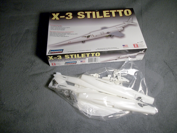
A fairly simple kit with not that many parts. The wing and tail plane are "one piece" parts. The fuselage has 5 parts although a few more if you include the UC doors but it does look to be nicely moulded.
Now to start working out how big to make it and the shape of the duct for a single EDF.
It will be back to a bifurcated inlet and exhaust as per the Sea Hawk!
Its by Lindberg.
A fairly simple kit with not that many parts. The wing and tail plane are "one piece" parts. The fuselage has 5 parts although a few more if you include the UC doors but it does look to be nicely moulded.
Now to start working out how big to make it and the shape of the duct for a single EDF.
It will be back to a bifurcated inlet and exhaust as per the Sea Hawk!
Attachments:
Thanks: Eric, Klipkopwildlife, Flytilbroke, THE BLACKBIRD
Please Log in or Create an account to join the conversation.
- Quorneng
-
Topic Author
- Offline
- Forum Master
-
Less
More
- Posts: 10058
- Thank you received: 19043
09 Jan 2024 15:16 #7
by Quorneng
Replied by Quorneng on topic Douglas X3 Stiletto
Nearly gone crazy but I have worked all day just playing with MS paint!.
First to 'clean up' the 3 view to remove all excess detail and ensure that all lines are properly black and just 1 pixel wide so it can be blown up to what ever size it needs to be .
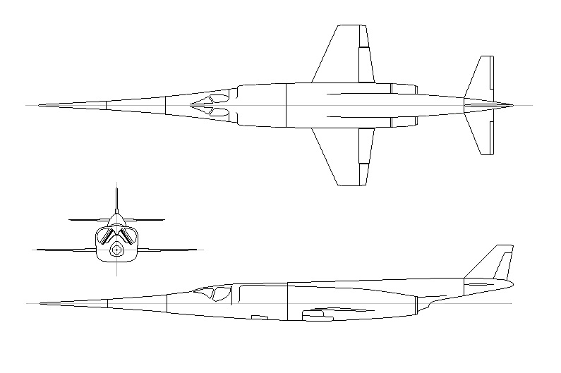
Also using 'cut and paste' to ensure both the left and right of an image are the same. Then make sure the 3 views actually line up with each other!
It quickly became obvious that the Stiletto inlets were very small compared to the exhausts. By pinching every available mm and eliminating the quite significant inlet 'bleed' ducts I managed to increase the effective inlet area by about 40% without altering the fuselage external profile..

With a bit of "eyeball" the total area of an equivalent circular duct was determined. I like the inlet duct to be 1.2 times the FSA (Fan Swept Area). This allowed the relative diameter of the fan to be determined. There are two exhausts whose combined area should total 90% of the FSA so each exhaust is a circle of 45% FSA.
I had now determined the key parameters of the duct.
Now on to a possible duct configuration
With the wings so far back, a short tail and long nose the EDF was going to have to be as far back as possible but still allow a reasonable bifurcated exhaust.
A "guestimate" of the CoG indicated the battery was going to be in between the inlet ducts and likely quite a bit behind the actual inlets. Thus the 'inefficient' inlet bifurcation was going to have to be quite long.
Overall I was beginning to think maybe an EDF Stiletto was not such a good idea.
Anyway I have sketched out on the 3 view drawing how the ducting might go.

Of course this is only in plan view. In reality the inlets are well above the line of the EDF & exhausts so the inlet will have to take that into account as well. It will be a nightmare to CAD for printing!
By this time it was 3pm, I had not had lunch and my brain hurt!
.
First to 'clean up' the 3 view to remove all excess detail and ensure that all lines are properly black and just 1 pixel wide so it can be blown up to what ever size it needs to be .
Also using 'cut and paste' to ensure both the left and right of an image are the same. Then make sure the 3 views actually line up with each other!
It quickly became obvious that the Stiletto inlets were very small compared to the exhausts. By pinching every available mm and eliminating the quite significant inlet 'bleed' ducts I managed to increase the effective inlet area by about 40% without altering the fuselage external profile..
With a bit of "eyeball" the total area of an equivalent circular duct was determined. I like the inlet duct to be 1.2 times the FSA (Fan Swept Area). This allowed the relative diameter of the fan to be determined. There are two exhausts whose combined area should total 90% of the FSA so each exhaust is a circle of 45% FSA.
I had now determined the key parameters of the duct.
Now on to a possible duct configuration
With the wings so far back, a short tail and long nose the EDF was going to have to be as far back as possible but still allow a reasonable bifurcated exhaust.
A "guestimate" of the CoG indicated the battery was going to be in between the inlet ducts and likely quite a bit behind the actual inlets. Thus the 'inefficient' inlet bifurcation was going to have to be quite long.
Overall I was beginning to think maybe an EDF Stiletto was not such a good idea.
Anyway I have sketched out on the 3 view drawing how the ducting might go.
Of course this is only in plan view. In reality the inlets are well above the line of the EDF & exhausts so the inlet will have to take that into account as well. It will be a nightmare to CAD for printing!
By this time it was 3pm, I had not had lunch and my brain hurt!
.
Attachments:
Thanks: Eric, Klipkopwildlife, Flytilbroke, THE BLACKBIRD
Please Log in or Create an account to join the conversation.
- Quorneng
-
Topic Author
- Offline
- Forum Master
-
Less
More
- Posts: 10058
- Thank you received: 19043
10 Jan 2024 13:55 #8
by Quorneng
Replied by Quorneng on topic Douglas X3 Stiletto
Started playing with FreeCAD and "lofting" to get an idea of what the duct might look like and how to actually design it!
I don't have a spare 50 mm EDF so there is no point in actually printing anything as they have to fit the EDF shell exactly and also match the EDF internal diameter so I created a dummy EDF of the right diameter and length, according to the web site.
There will be 7 printed parts (LW-PLA) as well as the EDF.
In CAD it will look something like this in side view .

And like this from the top.

Oh! and by the way it will be 1500 mm long (59") with a span of just 481 mm (18.9")
If it ends up weighing more than 350g (12oz) it will never fly!
I don't have a spare 50 mm EDF so there is no point in actually printing anything as they have to fit the EDF shell exactly and also match the EDF internal diameter so I created a dummy EDF of the right diameter and length, according to the web site.
There will be 7 printed parts (LW-PLA) as well as the EDF.
In CAD it will look something like this in side view .
And like this from the top.
Oh! and by the way it will be 1500 mm long (59") with a span of just 481 mm (18.9")
If it ends up weighing more than 350g (12oz) it will never fly!
Attachments:
Thanks: Eric, Klipkopwildlife
Please Log in or Create an account to join the conversation.
- Quorneng
-
Topic Author
- Offline
- Forum Master
-
Less
More
- Posts: 10058
- Thank you received: 19043
11 Jan 2024 17:32 #9
by Quorneng
Replied by Quorneng on topic Douglas X3 Stiletto
The duct layout I has chosen has some issues, particularly the long bifurcated inlet as two small ducts are less efficient than a single duct of the same area. I originally chose the long inlet bifurcation so I could place the flight battery between them. It occurred to me that if the battery could be placed under the duct the bifurcation could be shortened leaving the rest of the inlet to match the EDF casing diameter.
A further issue was the EDF location actually interfered with the wing. The Stiletto wing is so thin a single piece straight through layout would be preferred.. By inclining the EDF at 15 degrees it clears the wing with no sacrifice to the duct layout..

One advantage of a CAD 'lofted' duct is that in principle you only have to alter the XYZ coordinates of any of the duct cross sections and a single button press then recreates the duct, however with 7 individual duct sections it not quite a simple as that.
As a trial I have printed out the exhaust bifurcation section of the original duct layout.

The ends of the tail pipes are 'nozzles' together reducing to 90% of the FSA..
Commendably light complete it weight 4.4g.
Slow but finding any 'weaknesses' at this stage could prevent abject failure. .
A further issue was the EDF location actually interfered with the wing. The Stiletto wing is so thin a single piece straight through layout would be preferred.. By inclining the EDF at 15 degrees it clears the wing with no sacrifice to the duct layout..
One advantage of a CAD 'lofted' duct is that in principle you only have to alter the XYZ coordinates of any of the duct cross sections and a single button press then recreates the duct, however with 7 individual duct sections it not quite a simple as that.
As a trial I have printed out the exhaust bifurcation section of the original duct layout.
The ends of the tail pipes are 'nozzles' together reducing to 90% of the FSA..
Commendably light complete it weight 4.4g.
Slow but finding any 'weaknesses' at this stage could prevent abject failure. .
Attachments:
Thanks: Eric, Klipkopwildlife, Flytilbroke, THE BLACKBIRD
Please Log in or Create an account to join the conversation.
- Quorneng
-
Topic Author
- Offline
- Forum Master
-
Less
More
- Posts: 10058
- Thank you received: 19043
12 Jan 2024 22:52 - 12 Jan 2024 22:55 #10
by Quorneng
Replied by Quorneng on topic Douglas X3 Stiletto
Having created a CAD image of the first design duct I have now created the same for the second duct design.
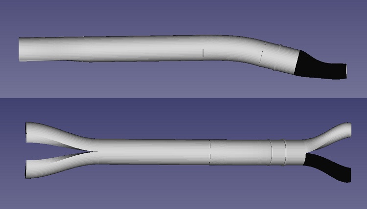
It certainly reduces the bifurcated length hopefully reducing the inlet losses and it leaves room for the wing to pass through the fuselage.
More for my own interest I compared the two designs side by side.

The fact that the left hand exhaust nozzle is black yet the right one is not is I believe down to the way I created it. It is purely a CAD "lighting" issue and makes no difference to CURA slicing and printing.
I am still waiting for the 50 mm EDF. then I can adjust the duct components either side of it fit properly to it.
Making up a full size plan is next.
So far I have only invested time as the 50 mm EDF could be used on anything so I can still "call it a day'" if it starts to look too silly.
 .
.
It certainly reduces the bifurcated length hopefully reducing the inlet losses and it leaves room for the wing to pass through the fuselage.
More for my own interest I compared the two designs side by side.
The fact that the left hand exhaust nozzle is black yet the right one is not is I believe down to the way I created it. It is purely a CAD "lighting" issue and makes no difference to CURA slicing and printing.
I am still waiting for the 50 mm EDF. then I can adjust the duct components either side of it fit properly to it.
Making up a full size plan is next.
So far I have only invested time as the 50 mm EDF could be used on anything so I can still "call it a day'" if it starts to look too silly.
Attachments:
Last edit: 12 Jan 2024 22:55 by Quorneng.
Thanks: Eric, Klipkopwildlife, Flytilbroke, THE BLACKBIRD
Please Log in or Create an account to join the conversation.
- THE BLACKBIRD
-

- Offline
- Forum Master
-
Less
More
- Posts: 6781
- Thank you received: 10722
13 Jan 2024 08:38 #11
by THE BLACKBIRD
Replied by THE BLACKBIRD on topic Douglas X3 Stiletto
Thats going to be a long crumperly nose on it, you will be repairing a long way back
Thanks: Klipkopwildlife
Please Log in or Create an account to join the conversation.
- Quorneng
-
Topic Author
- Offline
- Forum Master
-
Less
More
- Posts: 10058
- Thank you received: 19043
13 Jan 2024 13:00 #12
by Quorneng
Replied by Quorneng on topic Douglas X3 Stiletto
BB
Yes indeed. I might have to make some of it "knock off" but even so it will require very careful nose high landings.
It might also help to make the elevators a bit over scale too.
Yes indeed. I might have to make some of it "knock off" but even so it will require very careful nose high landings.
It might also help to make the elevators a bit over scale too.
Thanks: Klipkopwildlife, Flytilbroke
Please Log in or Create an account to join the conversation.
- Quorneng
-
Topic Author
- Offline
- Forum Master
-
Less
More
- Posts: 10058
- Thank you received: 19043
14 Jan 2024 23:03 - 14 Jan 2024 23:04 #13
by Quorneng
Replied by Quorneng on topic Douglas X3 Stiletto
My plan to have the EDF canted upward at 15 degrees has met a serious problem. Two of the lofted parts that join up to the EDF have inclined faces to match. You can loft this is Free Cad no problem but unfortunately in CURA you can't print a lofted article with an inclined face.
f the article was created by geometric parameters it would be no problem but I cannot even conceive how to make such complex shapes.
This is one of the parts in question.

There is something in a lofted part that CURA just does not recognise. The base and top planes must be parallel.
My first duct design was OK because all the lofted parts had parallel ends.
I shall have to think some more!
f the article was created by geometric parameters it would be no problem but I cannot even conceive how to make such complex shapes.
This is one of the parts in question.
There is something in a lofted part that CURA just does not recognise. The base and top planes must be parallel.
My first duct design was OK because all the lofted parts had parallel ends.
I shall have to think some more!
Attachments:
Last edit: 14 Jan 2024 23:04 by Quorneng.
Thanks: Klipkopwildlife, THE BLACKBIRD
Please Log in or Create an account to join the conversation.
- Klipkopwildlife
-

- Offline
- Administrator
-

- I'm supposed to be retired!
15 Jan 2024 03:19 #14
by Klipkopwildlife
Do it now, you may never get another chance
Replied by Klipkopwildlife on topic Douglas X3 Stiletto
Print with parallel ends then cut the end to the right angle?
Do it now, you may never get another chance
Thanks: THE BLACKBIRD
Please Log in or Create an account to join the conversation.
- Eric
-
- Offline
- Moderator
-
Less
More
- Posts: 15406
- Thank you received: 14306
15 Jan 2024 07:51 #15
by Eric
if you are calm and collected when all about you are going berserk - you've missed something important!
Replied by Eric on topic Douglas X3 Stiletto
Knock-off nose - held on by a couple of neo magnets?
if you are calm and collected when all about you are going berserk - you've missed something important!
Thanks: Klipkopwildlife, THE BLACKBIRD
Please Log in or Create an account to join the conversation.
Time to create page: 0.329 seconds