
- Posts: 10058
- Thank you received: 19043
Douglas X3 Stiletto
- Quorneng
-
 Topic Author
- Offline
- Forum Master
-

Less
More
16 Jan 2024 00:35 #16
by Quorneng
This is my mk3 duct.

Each of the 7 sections have parallel ends so avoiding the loft limitation.
The duct is inline with the intakes and runs in the upper part of the fuselage until aft of the EDF where the exhaust nozzle bifurcates and S bends to the bottom of the fuselage. This leaves plenty of room for the one piece wing and the LiPo to be placed under the duct.
I have test printed one half of the exhaust nozzle with the last of my LW-PLA. it printed OK and weighs just 1.8g.

I am hoping the complete duct in LW-PLA will weigh about 40g.
When the inlet and exhaust duct sections are glued to the EDF it will be 234mm long. It will then act as the "spine" around which the fuselage will be built.
The duct will only be finalised and printed when the EDF arrives from China.
Another kg roll of LW-PLA is due from Amazon tomorrow.
.
Replied by Quorneng on topic Douglas X3 Stiletto
Unfortunately each section is not simply a butt joint to its neighbour but will have a close fitting overlap joint printed at the same time so a cut off end is not practicable.Print with parallel ends then cut the end to the right angle?
This is my mk3 duct.
Each of the 7 sections have parallel ends so avoiding the loft limitation.
The duct is inline with the intakes and runs in the upper part of the fuselage until aft of the EDF where the exhaust nozzle bifurcates and S bends to the bottom of the fuselage. This leaves plenty of room for the one piece wing and the LiPo to be placed under the duct.
I have test printed one half of the exhaust nozzle with the last of my LW-PLA. it printed OK and weighs just 1.8g.
I am hoping the complete duct in LW-PLA will weigh about 40g.
When the inlet and exhaust duct sections are glued to the EDF it will be 234mm long. It will then act as the "spine" around which the fuselage will be built.
The duct will only be finalised and printed when the EDF arrives from China.
Another kg roll of LW-PLA is due from Amazon tomorrow.
.
Attachments:
Thanks: Klipkopwildlife, THE BLACKBIRD
Please Log in or Create an account to join the conversation.
- Quorneng
-
Topic Author
- Offline
- Forum Master
-
Less
More
- Posts: 10058
- Thank you received: 19043
18 Jan 2024 15:23 #17
by Quorneng
Replied by Quorneng on topic Douglas X3 Stiletto
I have printed out the mk3 duct in LW-PLA with a dummy EDF in PLA. The slow boat from China is expected end Jan!

It has come out a good bit lighter than I expected, just 16g.rather than my feared 40g.
The only concern is the bifurcated inlets. I expect that the flat areas will need significant support to prevent them collapsing. The rest of the inlet duct is circular so should be OK.
When the duct is Installed in the plane I will add a bit of a non scale bell mouth to each inlet to hopefully limit inlet losses. The full size had sharp edged supersonic inlets.
It has come out a good bit lighter than I expected, just 16g.rather than my feared 40g.
The only concern is the bifurcated inlets. I expect that the flat areas will need significant support to prevent them collapsing. The rest of the inlet duct is circular so should be OK.
When the duct is Installed in the plane I will add a bit of a non scale bell mouth to each inlet to hopefully limit inlet losses. The full size had sharp edged supersonic inlets.
Attachments:
Thanks: Klipkopwildlife
Please Log in or Create an account to join the conversation.
- Quorneng
-
Topic Author
- Offline
- Forum Master
-
Less
More
- Posts: 10058
- Thank you received: 19043
25 Jan 2024 19:55 #18
by Quorneng
Replied by Quorneng on topic Douglas X3 Stiletto
At last the 50mm EDF has arrived.
My dummy EDF proved to be no quite the right size so I had to do some reprinting to get the ducts to fit the EDF exactly.

Initially I just glued on the exhaust part of the duct and ran it on a partially charged 4s. It drew 261W. It certainly pushed quite hard but holding tan EDF at full power 'in hand' is not exactly to be recommended.
At this point I felt like the combined exhaust nozzle area looked rather small compared to that of the FSA so I rechecked my calculations. Instead of the intended total to be 90% of the FSA it was actually just 55%. Oops!. Some CAD changes and reprinting required. Just as well the LW=PLA reel has arrived.
On the plus side the inlet duct looks OK.
Hopefully when it is all done right yjr complete duct will achieve my "close the door" test.
My dummy EDF proved to be no quite the right size so I had to do some reprinting to get the ducts to fit the EDF exactly.
Initially I just glued on the exhaust part of the duct and ran it on a partially charged 4s. It drew 261W. It certainly pushed quite hard but holding tan EDF at full power 'in hand' is not exactly to be recommended.
At this point I felt like the combined exhaust nozzle area looked rather small compared to that of the FSA so I rechecked my calculations. Instead of the intended total to be 90% of the FSA it was actually just 55%. Oops!. Some CAD changes and reprinting required. Just as well the LW=PLA reel has arrived.
On the plus side the inlet duct looks OK.
Hopefully when it is all done right yjr complete duct will achieve my "close the door" test.
Attachments:
Thanks: Eric, Klipkopwildlife, THE BLACKBIRD
Please Log in or Create an account to join the conversation.
- Quorneng
-
Topic Author
- Offline
- Forum Master
-
Less
More
- Posts: 10058
- Thank you received: 19043
26 Jan 2024 12:29 #19
by Quorneng
Replied by Quorneng on topic Douglas X3 Stiletto
The effect of my miscalculation is quite significant.

The "correct" size exhaust is on the right.
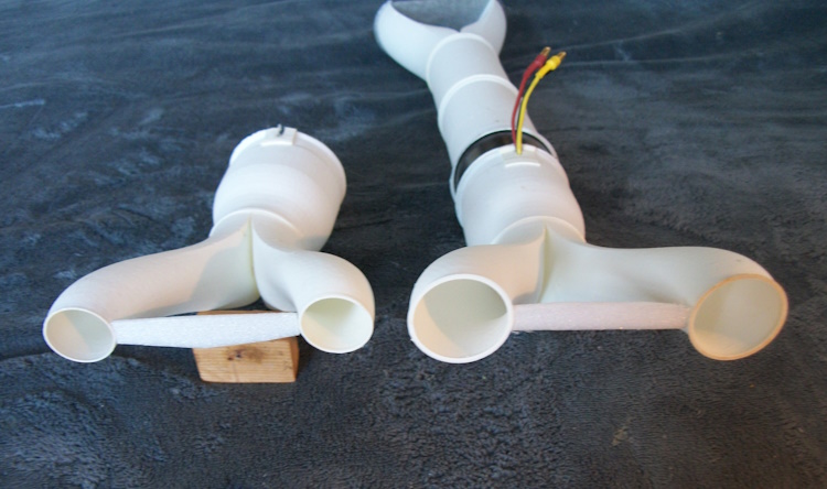
I did do a "close the door" test using the small exhaust. It did just but only with a fully charged 4s.
Video of the test with the bigger exhaust in due course..
I have no way of actually measuring the thrust at this stage so what ever it ends up at I will just have to live with!
The "correct" size exhaust is on the right.
I did do a "close the door" test using the small exhaust. It did just but only with a fully charged 4s.
Video of the test with the bigger exhaust in due course..
I have no way of actually measuring the thrust at this stage so what ever it ends up at I will just have to live with!
Attachments:
Thanks: Eric, Klipkopwildlife, THE BLACKBIRD
Please Log in or Create an account to join the conversation.
- Quorneng
-
Topic Author
- Offline
- Forum Master
-
Less
More
- Posts: 10058
- Thank you received: 19043
26 Jan 2024 22:59 - 26 Jan 2024 23:03 #20
by Quorneng
Replied by Quorneng on topic Douglas X3 Stiletto
Here is the test video.
These 50 mm EDFs are superbly balanced indeed the instructions state that if you remove the fan screw they will not accept a returns!
In the course of testing I discovered that the left hand exhaust produces close to 11% more thrust than the right!.
As far as I can tell each exhaust is geometrically identical and are fed by exactly half the duct area from the EDF. Furthermore the EDF itself is exactly in the middle of the duct.
Very strange!
I do wonder if the fact the airflow is rotating as it leaves the fan coupled with the "S" bend downward in both ducts means that one is effected more than the other, Maybe my original concept of putting the S bend in the inlet duct would solve the problem.
I might have to do quite a bit more printing to find out..
These 50 mm EDFs are superbly balanced indeed the instructions state that if you remove the fan screw they will not accept a returns!
In the course of testing I discovered that the left hand exhaust produces close to 11% more thrust than the right!.
As far as I can tell each exhaust is geometrically identical and are fed by exactly half the duct area from the EDF. Furthermore the EDF itself is exactly in the middle of the duct.
Very strange!
I do wonder if the fact the airflow is rotating as it leaves the fan coupled with the "S" bend downward in both ducts means that one is effected more than the other, Maybe my original concept of putting the S bend in the inlet duct would solve the problem.
I might have to do quite a bit more printing to find out..
Last edit: 26 Jan 2024 23:03 by Quorneng. Reason: Spelling
Thanks: Eric, Klipkopwildlife
Please Log in or Create an account to join the conversation.
- Quorneng
-
Topic Author
- Offline
- Forum Master
-
Less
More
- Posts: 10058
- Thank you received: 19043
27 Jan 2024 22:42 #21
by Quorneng
Replied by Quorneng on topic Douglas X3 Stiletto
Puzzled by the asymmetric thrust I reprinted the exhaust whole exhaust duct still with same bifurcation but with the exhaust nozzle inline with the EDF centre line.

The same test as before showed each nozzle created exactly the same thrust when directed onto a weight scale to a gram!
This means I would need to place the EDF low down in the fuselage inline with the exhausts which would place the duct inline with the wing.
.To allow this the wing would have to pass around the duct, probably both above and below. Perfectly possible but it would concentrate the bending forces into a relatively small and thus heavy component.
I have compared the proposed size X3 wing area against that of my foam Hawker Hunter, which uses the same EDF, I have concluded the X3 needs to be at least 20% bigger to avoid a near double wing loading.
There are other advantages going down this route.
a) The EDF will be relatively smaller in the fuselage so the wing can pass under the duct with only a slight joggle
b) The inlets are bigger allowing the whole inlet duct to be a generous 1.3 times the FSA.
c) As all the heavy bits will be the same and the airframe made from the same 3mm Depron the overall weigh increase will only be a small fraction of the wing area increase..
The downside is it will be nearly 6ft long with a span of just under 2ft.

A rough estimate based on the "heavy" components I have indicate an all up weight close to 400g is possible. This would give the "bigger" X-3 a wing loading not that much higher than the relatively slow flying Hunter.
Back to the drawing board and the printer!
The same test as before showed each nozzle created exactly the same thrust when directed onto a weight scale to a gram!
This means I would need to place the EDF low down in the fuselage inline with the exhausts which would place the duct inline with the wing.
.To allow this the wing would have to pass around the duct, probably both above and below. Perfectly possible but it would concentrate the bending forces into a relatively small and thus heavy component.
I have compared the proposed size X3 wing area against that of my foam Hawker Hunter, which uses the same EDF, I have concluded the X3 needs to be at least 20% bigger to avoid a near double wing loading.
There are other advantages going down this route.
a) The EDF will be relatively smaller in the fuselage so the wing can pass under the duct with only a slight joggle
b) The inlets are bigger allowing the whole inlet duct to be a generous 1.3 times the FSA.
c) As all the heavy bits will be the same and the airframe made from the same 3mm Depron the overall weigh increase will only be a small fraction of the wing area increase..
The downside is it will be nearly 6ft long with a span of just under 2ft.
A rough estimate based on the "heavy" components I have indicate an all up weight close to 400g is possible. This would give the "bigger" X-3 a wing loading not that much higher than the relatively slow flying Hunter.
Back to the drawing board and the printer!
Attachments:
Thanks: Klipkopwildlife
Please Log in or Create an account to join the conversation.
- Eric
-

- Offline
- Moderator
-

Less
More
- Posts: 15406
- Thank you received: 14306
27 Jan 2024 23:13 #22
by Eric
if you are calm and collected when all about you are going berserk - you've missed something important!
Replied by Eric on topic Douglas X3 Stiletto
nearly 6ft long with a span of just under 2ft.
It will have the pitch response of a laden coal barge, but roll like a drill-bit!

It will have the pitch response of a laden coal barge, but roll like a drill-bit!
if you are calm and collected when all about you are going berserk - you've missed something important!
Thanks: Klipkopwildlife, Quorneng
Please Log in or Create an account to join the conversation.
- Quorneng
-
Topic Author
- Offline
- Forum Master
-
Less
More
- Posts: 10058
- Thank you received: 19043
31 Jan 2024 13:44 #23
by Quorneng
Replied by Quorneng on topic Douglas X3 Stiletto
Still working on the duct layout. This shows the thinking with the exhaust ducts.
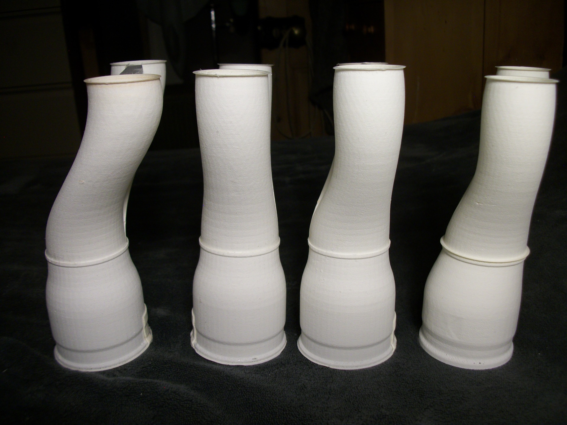
First left is the off set duct to get the EDF above of the wing. It generated less thrust on the right nozzle (looking from the front) then the left.
2nd left is the zero off set test duct. It showed equal thrust left and right but it would put the EDF right in the middle of the wing.
Increasing the overall size of the X3 indicated that it would only take a slight off set for the EDF to clear the wing.
3rd from the left is a test duct where the nozzles are off set so their underside is level with the duct inlet.
4th from the left has the duct from to the bifurcate duct entrance is level with the underside of the EDF case. All the bottom of the complete exhaust are at the same level keeping the EDF high wit the minimum of duct offset. Hopefully this layout will not suffer the same unequal thrust but it has not been tested yet.
If it does show un equal thrust then its back to designing a wing spar arrangement that goes around the EDF.
After all this it had better fly!
First left is the off set duct to get the EDF above of the wing. It generated less thrust on the right nozzle (looking from the front) then the left.
2nd left is the zero off set test duct. It showed equal thrust left and right but it would put the EDF right in the middle of the wing.
Increasing the overall size of the X3 indicated that it would only take a slight off set for the EDF to clear the wing.
3rd from the left is a test duct where the nozzles are off set so their underside is level with the duct inlet.
4th from the left has the duct from to the bifurcate duct entrance is level with the underside of the EDF case. All the bottom of the complete exhaust are at the same level keeping the EDF high wit the minimum of duct offset. Hopefully this layout will not suffer the same unequal thrust but it has not been tested yet.
If it does show un equal thrust then its back to designing a wing spar arrangement that goes around the EDF.
After all this it had better fly!
Attachments:
Thanks: Eric, Klipkopwildlife, Flytilbroke
Please Log in or Create an account to join the conversation.
- Eric
-
- Offline
- Moderator
-
Less
More
- Posts: 15406
- Thank you received: 14306
31 Jan 2024 15:01 #24
by Eric
if you are calm and collected when all about you are going berserk - you've missed something important!
Replied by Eric on topic Douglas X3 Stiletto
Translation, please! -
4th from the left has the duct from to the bifurcate duct entrance is level with the underside of the EDF case.
4th from the left has the duct from to the bifurcate duct entrance is level with the underside of the EDF case.
if you are calm and collected when all about you are going berserk - you've missed something important!
Thanks: Klipkopwildlife
Please Log in or Create an account to join the conversation.
- Quorneng
-
Topic Author
- Offline
- Forum Master
-
Less
More
- Posts: 10058
- Thank you received: 19043
31 Jan 2024 19:48 #25
by Quorneng
Replied by Quorneng on topic Douglas X3 Stiletto
Perhaps this picture better describes the intention of exhaust mk4.
 duct.
duct.
The exhaust nozzles are sae low in the X3 fuselage so to avoid something sticking out of the underneath of the fuselage the bottom edge of the nozzles. exhaust duct and EDF are at the same level but hopefully a layout close enough to the duct all on the EDF centre line to avoid the left exhaust nozzle giving less thrust than the right..
The exhaust nozzles are sae low in the X3 fuselage so to avoid something sticking out of the underneath of the fuselage the bottom edge of the nozzles. exhaust duct and EDF are at the same level but hopefully a layout close enough to the duct all on the EDF centre line to avoid the left exhaust nozzle giving less thrust than the right..
Attachments:
Thanks: Klipkopwildlife
Please Log in or Create an account to join the conversation.
- Quorneng
-
Topic Author
- Offline
- Forum Master
-
Less
More
- Posts: 10058
- Thank you received: 19043
01 Feb 2024 19:41 #26
by Quorneng
Replied by Quorneng on topic Douglas X3 Stiletto
To my surprise and disappointment the duct demonstrated asymmetric thrust nearly as badly as the first one!
So its on the printing the final "inline" exhaust duct along with the final inlet duct with the overall length and inlet size to match the "bigger" Stiletto.
Once that is done then create some sort of spar arrangement to go round the duct.
So its on the printing the final "inline" exhaust duct along with the final inlet duct with the overall length and inlet size to match the "bigger" Stiletto.
Once that is done then create some sort of spar arrangement to go round the duct.
Thanks: Klipkopwildlife
Please Log in or Create an account to join the conversation.
- Eric
-
- Offline
- Moderator
-
Less
More
- Posts: 15406
- Thank you received: 14306
01 Feb 2024 20:35 #27
by Eric
if you are calm and collected when all about you are going berserk - you've missed something important!
Replied by Eric on topic Douglas X3 Stiletto
Perhaps you could put a small 'choke' in the duct with the greater flow, to alter the balance and maybe get them more symmetrical?
if you are calm and collected when all about you are going berserk - you've missed something important!
Please Log in or Create an account to join the conversation.
- Quorneng
-
Topic Author
- Offline
- Forum Master
-
Less
More
- Posts: 10058
- Thank you received: 19043
01 Feb 2024 22:50 #28
by Quorneng
Replied by Quorneng on topic Douglas X3 Stiletto
A small choke could equalise the thrusts but I not sure yet whether I can afford to loose any thrust at this stage. I still prefer the duct in a line solution..
I did run the EDF by itself "in hand" and it is certainly became apparent that the ducts are costing quite a bit of thrust If you can tell the difference it is probably quite significant maybe 30%? I really don't want to loose any more!
This is what the" Inline" duct will look like set again the big X3 plan.

The EDF itself is very close to the bottom of the fuselage but it does fit. It also shows that quite a bit of the duct obstructs the wing.
The exhaust nozzles will be quite a bit under scale size on the big x3. The upside is the inlets will have an area that is a genuine 1.2 times the FSA.
The EDF is claimed to give 750g thrust on a 4s, maybe 400g on a 3s.. Then loose 25% in the ducting so 300g. My guesstimate weight is 350g with a 1500mAh 3s. Not much to spare!
I did run the EDF by itself "in hand" and it is certainly became apparent that the ducts are costing quite a bit of thrust If you can tell the difference it is probably quite significant maybe 30%? I really don't want to loose any more!
This is what the" Inline" duct will look like set again the big X3 plan.
The EDF itself is very close to the bottom of the fuselage but it does fit. It also shows that quite a bit of the duct obstructs the wing.
The exhaust nozzles will be quite a bit under scale size on the big x3. The upside is the inlets will have an area that is a genuine 1.2 times the FSA.
The EDF is claimed to give 750g thrust on a 4s, maybe 400g on a 3s.. Then loose 25% in the ducting so 300g. My guesstimate weight is 350g with a 1500mAh 3s. Not much to spare!
Attachments:
Thanks: Eric, Klipkopwildlife, Flytilbroke
Please Log in or Create an account to join the conversation.
- Quorneng
-
Topic Author
- Offline
- Forum Master
-
Less
More
- Posts: 10058
- Thank you received: 19043
04 Feb 2024 15:41 #29
by Quorneng
Replied by Quorneng on topic Douglas X3 Stiletto
What is hopefully the final mk5 version duct for the bigger X3 with a 2ft rule for comparison.

In this view it is upside down (inlet at the bottom) as the glue is still drying.
The only bit still to design and print are the inlet bell mouths. The inlet area is fairly generous on the bigger X3 but every little helps.
I hope to create a method of measuring the thrust before I actually start construction.
In this view it is upside down (inlet at the bottom) as the glue is still drying.
The only bit still to design and print are the inlet bell mouths. The inlet area is fairly generous on the bigger X3 but every little helps.
I hope to create a method of measuring the thrust before I actually start construction.
Attachments:
Thanks: Eric, Klipkopwildlife
Please Log in or Create an account to join the conversation.
- Quorneng
-
Topic Author
- Offline
- Forum Master
-
Less
More
- Posts: 10058
- Thank you received: 19043
05 Feb 2024 16:17 - 05 Feb 2024 16:22 #30
by Quorneng
Replied by Quorneng on topic Douglas X3 Stiletto
Well its looks like I will have to reprint the inlet part of the duct as I hade a miscalculation on the positions on the inlets them selves.
 Not much filament needed but the printing does take about 5 hours.
More as a test I designed two inlet bell mouths. They are separate items that are glued on.

I originally designed them as individual CAD files for left and right. Their rather complex shape made it hard to get them an exact mirror image then I remembered CURA has a "mirror image" facility. Perfect left and right copies on the click of the mouse. Drat!
Then I could have done exactly the same for the left and right inlet ducts themselves and saved myself several hours.. Double Drat!
I now have a dimensionally correct single "master" inlet duct that will be printed and then mirrored for perfect left and right items.
Anyway I have run the duct as is on a fully charged big 3s to see what happens.
It certainly passed my "blow the door shut" test.
Maybe it is time to actually start building the airframe.
More as a test I designed two inlet bell mouths. They are separate items that are glued on.
I originally designed them as individual CAD files for left and right. Their rather complex shape made it hard to get them an exact mirror image then I remembered CURA has a "mirror image" facility. Perfect left and right copies on the click of the mouse. Drat!
Then I could have done exactly the same for the left and right inlet ducts themselves and saved myself several hours.. Double Drat!
I now have a dimensionally correct single "master" inlet duct that will be printed and then mirrored for perfect left and right items.
Anyway I have run the duct as is on a fully charged big 3s to see what happens.
It certainly passed my "blow the door shut" test.
Maybe it is time to actually start building the airframe.
Attachments:
Last edit: 05 Feb 2024 16:22 by Quorneng.
Thanks: Eric, Klipkopwildlife, Flytilbroke
Please Log in or Create an account to join the conversation.
Time to create page: 0.296 seconds