
- Posts: 9436
- Thank you received: 19043
DH SEA VIXEN for 40 mm EDFs
- Quorneng
-
 Topic Author
- Offline
- Forum Master
-

Less
More
12 Jul 2017 10:45 - 12 Jul 2017 10:45 #16
by Quorneng
Replied by Quorneng on topic DH SEA VIXEN for 40 mm EDFs
With the other side formers glued in a start can be made on the planking.
First a beam is temporarily glued across the back to keep it all square.
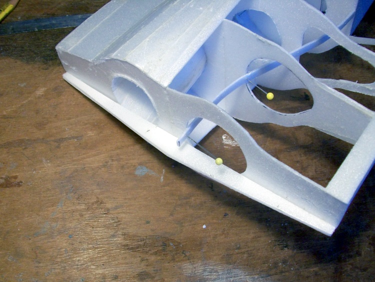
The first few planks simply help to stabilise the formers.
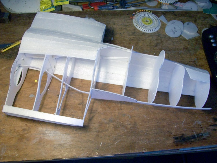
To give the best access the duct will be planked first. Creating an "S" shaped tube that changes section from a circle to a triangle along its length and on the inside of the formers makes for a very tedious job.
First a beam is temporarily glued across the back to keep it all square.
The first few planks simply help to stabilise the formers.
To give the best access the duct will be planked first. Creating an "S" shaped tube that changes section from a circle to a triangle along its length and on the inside of the formers makes for a very tedious job.
Last edit: 12 Jul 2017 10:45 by Quorneng.
Thanks: Phil Wood, Klipkopwildlife, blue123, Ralpharr2001, boz, Firewood, Squirrelnet
Please Log in or Create an account to join the conversation.
- Firewood
-

- Offline
- Elite Member
-

Less
More
- Posts: 219
- Thank you received: 268
12 Jul 2017 12:19 #17
by Firewood
I'm so clever that sometimes I don't understand a single word of what I'm saying.
Replied by Firewood on topic DH SEA VIXEN for 40 mm EDFs
Very impressive 
I'm so clever that sometimes I don't understand a single word of what I'm saying.
Please Log in or Create an account to join the conversation.
- Quorneng
-
Topic Author
- Offline
- Forum Master
-
Less
More
- Posts: 9436
- Thank you received: 19043
13 Jul 2017 19:29 - 13 Jul 2017 19:29 #18
by Quorneng
Replied by Quorneng on topic DH SEA VIXEN for 40 mm EDFs
Before the outer skin can progress the RH inlet duct has to be planked.
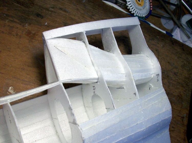
Actually slower to do that the first as the rather delicate structure has to be handled whereas for the first half was held firmly on the building board.
Actually slower to do that the first as the rather delicate structure has to be handled whereas for the first half was held firmly on the building board.
Last edit: 13 Jul 2017 19:29 by Quorneng.
Thanks: Phil Wood, Klipkopwildlife, boz, Firewood
Please Log in or Create an account to join the conversation.
- Quorneng
-
Topic Author
- Offline
- Forum Master
-
Less
More
- Posts: 9436
- Thank you received: 19043
14 Jul 2017 23:05 #19
by Quorneng
Replied by Quorneng on topic DH SEA VIXEN for 40 mm EDFs
With the EDF part added to the fuselage a trial 'positioning' fit of the wings.

The above bits weigh 5.1 oz (144 g).
The next step is to install the ESCs and wire them up to the EDFs to allow the majority of the fuselage planking to be completed as in its current form it is difficult to handle without damage, however enough access will still have to be left to run the elevator servo wire.
The wings will then be fitted followed by the booms (they fit on the wings) and tail. Only then can the battery position be determined allowing the cockpit area to be completed.
Well that the 'new' plan.
Thanks: Phil Wood, Klipkopwildlife, blue123, boz, Firewood, Squirrelnet
Please Log in or Create an account to join the conversation.
- Quorneng
-
Topic Author
- Offline
- Forum Master
-
Less
More
- Posts: 9436
- Thank you received: 19043
16 Jul 2017 12:17 #20
by Quorneng
Replied by Quorneng on topic DH SEA VIXEN for 40 mm EDFs
The complex shape of the planking is slow going but at least the underside is more or less complete.

Some of the top planking still to do for strength and then wire up the motors and ESCs.
Some of the top planking still to do for strength and then wire up the motors and ESCs.
Thanks: Phil Wood, Eric, Klipkopwildlife, blue123, Ralpharr2001, boz, Firewood, Squirrelnet
Please Log in or Create an account to join the conversation.
- Quorneng
-
Topic Author
- Offline
- Forum Master
-
Less
More
- Posts: 9436
- Thank you received: 19043
16 Jul 2017 22:47 #21
by Quorneng
Replied by Quorneng on topic DH SEA VIXEN for 40 mm EDFs
The motors wired up to the ESCs using "magnet" wire to save weight.

The ESCs are temporarily connected for testing..
The "bare" heat sinks of the ESCs are mounted flush in the intakes to ensure good cooling but without creating drag..

With a bit more planking for structural integrity it should be possible to do thrust test 'nose down' on the scales.
The ESCs are temporarily connected for testing..
The "bare" heat sinks of the ESCs are mounted flush in the intakes to ensure good cooling but without creating drag..
With a bit more planking for structural integrity it should be possible to do thrust test 'nose down' on the scales.
Thanks: Klipkopwildlife, blue123, Ralpharr2001, boz, Firewood, Squirrelnet
Please Log in or Create an account to join the conversation.
- Quorneng
-
Topic Author
- Offline
- Forum Master
-
Less
More
- Posts: 9436
- Thank you received: 19043
17 Jul 2017 14:19 #22
by Quorneng
Replied by Quorneng on topic DH SEA VIXEN for 40 mm EDFs
With the ESC temporarily connected to a big 2s LiPo and controlled by a servo tester the first test run of the 40 mm EDFs.
At 240 W input it is an incredibly inefficient and noisy way of creating 'not a lot' of thrust! :woohoo:
But at least you will be able to hear it
At 240 W input it is an incredibly inefficient and noisy way of creating 'not a lot' of thrust! :woohoo:
But at least you will be able to hear it
Thanks: Phil Wood, Klipkopwildlife, blue123, one tenor, Firewood
Please Log in or Create an account to join the conversation.
- boz
-

- Offline
- Platinum Member
-

Less
More
- Posts: 1176
- Thank you received: 1420
17 Jul 2017 17:03 #23
by boz
Replied by boz on topic DH SEA VIXEN for 40 mm EDFs
"Wow" your right, ear defenders a must, :woohoo:
Please Log in or Create an account to join the conversation.
- Eric
-

- Offline
- Moderator
-

Less
More
- Posts: 13726
- Thank you received: 14467
17 Jul 2017 18:42 #24
by Eric
if you are calm and collected when all about you are going berserk - you've missed something important!
Replied by Eric on topic DH SEA VIXEN for 40 mm EDFs
There's enough draft to blow the cupboard door about!
Don't forget - with edf's, the faster the model moves through the air, the more draft you get - when static like that, the fan blades are stalling at higher rpm's, because they are quite high pitched.
Don't forget - with edf's, the faster the model moves through the air, the more draft you get - when static like that, the fan blades are stalling at higher rpm's, because they are quite high pitched.
if you are calm and collected when all about you are going berserk - you've missed something important!
Thanks: boz, Firewood
Please Log in or Create an account to join the conversation.
- Quorneng
-
Topic Author
- Offline
- Forum Master
-
Less
More
- Posts: 9436
- Thank you received: 19043
18 Jul 2017 19:30 - 18 Jul 2017 19:44 #25
by Quorneng
Replied by Quorneng on topic DH SEA VIXEN for 40 mm EDFs
Slowly creeping forward, the wings attached.

Now comes the fun bit - building the booms and then attaching them to the wings.
No idea yet how to do any of it so quite a bit of "make it up as you go along" will be required..
Eric
Not quite sure about the EDF blades stalling.
I seem to recall there is a critical pitch angle for a prop below which it cannot stall even in still air.
The EDF blades may be above that pitch angle but providing the inlet is not too restrictive the blades are not operating in still air as it is already travelling at speed down the inlet duct even when the plane is stationary.
Last edit: 18 Jul 2017 19:44 by Quorneng.
Thanks: Eric, Klipkopwildlife, boz, Firewood, Crashrr
Please Log in or Create an account to join the conversation.
- Quorneng
-
Topic Author
- Offline
- Forum Master
-
Less
More
- Posts: 9436
- Thank you received: 19043
22 Jul 2017 14:41 #26
by Quorneng
Replied by Quorneng on topic DH SEA VIXEN for 40 mm EDFs
The booms are proving to be very slow going.
They will be made in two sections. The boom and a fin section.
Rather too long and thin to plank, let alone in 2 mm, with an awful lot of bits but I have more or less completed one boom. Light enough at 7.2 g although I am not completely happy with it.

Now all I have to do is make another, hopefully better, whilst the techniques used are still fresh in my mind.
They will be made in two sections. The boom and a fin section.
Rather too long and thin to plank, let alone in 2 mm, with an awful lot of bits but I have more or less completed one boom. Light enough at 7.2 g although I am not completely happy with it.
Now all I have to do is make another, hopefully better, whilst the techniques used are still fresh in my mind.
Thanks: Klipkopwildlife, boz, Firewood
Please Log in or Create an account to join the conversation.
- Quorneng
-
Topic Author
- Offline
- Forum Master
-
Less
More
- Posts: 9436
- Thank you received: 19043
23 Jul 2017 10:43 - 23 Jul 2017 10:44 #27
by Quorneng
Replied by Quorneng on topic DH SEA VIXEN for 40 mm EDFs
The first half of the second boom under construction.

The 'outline' of the boom to which the formers are glued is temporary and is removed once it is lifted.
The 'outline' of the boom to which the formers are glued is temporary and is removed once it is lifted.
Last edit: 23 Jul 2017 10:44 by Quorneng.
Thanks: Klipkopwildlife, blue123, boz, Firewood
Please Log in or Create an account to join the conversation.
- Quorneng
-
Topic Author
- Offline
- Forum Master
-
Less
More
- Posts: 9436
- Thank you received: 19043
25 Jul 2017 21:56 - 25 Jul 2017 21:57 #28
by Quorneng
Replied by Quorneng on topic DH SEA VIXEN for 40 mm EDFs
At last a bit of progress.
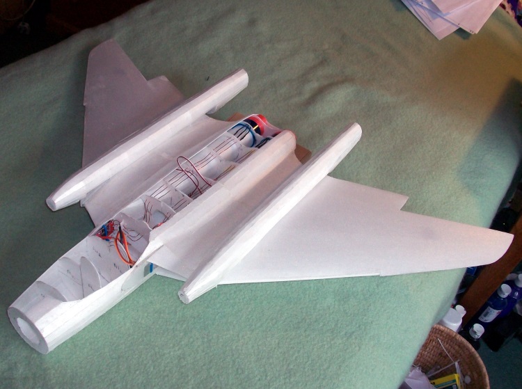
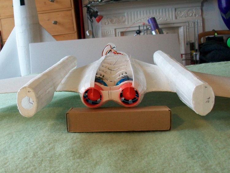
The hole through the left hand boom is for the elevator servo wire.
They are only 'positioned' in place but are pretty much symmetrical.
The tail fin sections will be added to each boom before they are glued to the wings.
The tail plane will then be made to simply 'fit the gap' between the fins!
The hole through the left hand boom is for the elevator servo wire.
They are only 'positioned' in place but are pretty much symmetrical.
The tail fin sections will be added to each boom before they are glued to the wings.
The tail plane will then be made to simply 'fit the gap' between the fins!
Last edit: 25 Jul 2017 21:57 by Quorneng.
Thanks: Klipkopwildlife, blue123, boz, Firewood
Please Log in or Create an account to join the conversation.
- Quorneng
-
Topic Author
- Offline
- Forum Master
-
Less
More
- Posts: 9436
- Thank you received: 19043
28 Jul 2017 14:30 - 28 Jul 2017 14:31 #29
by Quorneng
Replied by Quorneng on topic DH SEA VIXEN for 40 mm EDFs
The first fin assembly added to a boom.
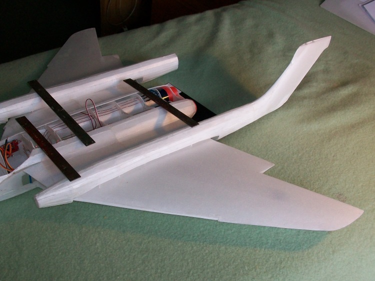
Still only resting in place.
As weight at the back is so critical the fin, like the wing, is basically a hollow 2 mm Depron structure but it does require rather more individual planks to create the smooth shape change from the oval boom to the aerofoil fin section.
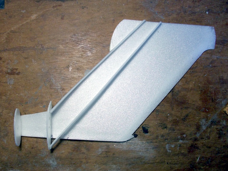
Still only resting in place.
As weight at the back is so critical the fin, like the wing, is basically a hollow 2 mm Depron structure but it does require rather more individual planks to create the smooth shape change from the oval boom to the aerofoil fin section.
Last edit: 28 Jul 2017 14:31 by Quorneng.
Thanks: Klipkopwildlife, blue123, Ralpharr2001, boz, Firewood
Please Log in or Create an account to join the conversation.
- Klipkopwildlife
-

- Offline
- Administrator
-

- I'm supposed to be retired!
29 Jul 2017 08:19 #30
by Klipkopwildlife
Do it now, you may never get another chance
Replied by Klipkopwildlife on topic DH SEA VIXEN for 40 mm EDFs
I watch in awe Stephen! At this scale I would be worried about size and orientation while flying, I have trouble with my Blizzard and that's 'only' 1.4Metres
Do it now, you may never get another chance
Thanks: boz
Please Log in or Create an account to join the conversation.
Time to create page: 0.772 seconds