
- Posts: 9436
- Thank you received: 19043
P1081 The 'straight through' swept wing Sea Hawk
- Quorneng
-
 Topic Author
- Offline
- Forum Master
-

Less
More
27 Jul 2021 23:23 #1
by Quorneng
P1081 The 'straight through' swept wing Sea Hawk was created by Quorneng
I found this picture of the P1081.

Clearly shows the new tail end attached to what was the second P1052. Must have only just been rolled out as it is unpainted.
When I started looking at the 3 view 'loosing' the twin exhausts means there were quite a few changes to the whole wing root. They even made the intakes a little bit smaller.
I don't have a 'spare' 55 mm EDF so I have had to order one from AliExpress to be delivered from Canada!
Spent a ridiculous amount of time redesigning the inlet duct to take into account the smaller inlets.
A CAD view of the new inlet duct.

CURA say it will take 3 hrs 8 minutes to print. :woohoo:
It should be a little bit more efficient than the P1052's inlet as each duct is at 39 degrees to the centre line rather than 45 previously.
The simple exhaust duct should be more efficient as well but I can't do much with that until the new EDF arrives.
Clearly shows the new tail end attached to what was the second P1052. Must have only just been rolled out as it is unpainted.
When I started looking at the 3 view 'loosing' the twin exhausts means there were quite a few changes to the whole wing root. They even made the intakes a little bit smaller.
I don't have a 'spare' 55 mm EDF so I have had to order one from AliExpress to be delivered from Canada!
Spent a ridiculous amount of time redesigning the inlet duct to take into account the smaller inlets.
A CAD view of the new inlet duct.
CURA say it will take 3 hrs 8 minutes to print. :woohoo:
It should be a little bit more efficient than the P1052's inlet as each duct is at 39 degrees to the centre line rather than 45 previously.
The simple exhaust duct should be more efficient as well but I can't do much with that until the new EDF arrives.
Thanks: Klipkopwildlife, Flytilbroke, THE BLACKBIRD
Please Log in or Create an account to join the conversation.
- Quorneng
-
Topic Author
- Offline
- Forum Master
-
Less
More
- Posts: 9436
- Thank you received: 19043
29 Jul 2021 14:09 #2
by Quorneng
Replied by Quorneng on topic P1081 The 'straight through' swept wing Sea Hawk
The inlet duct printed.
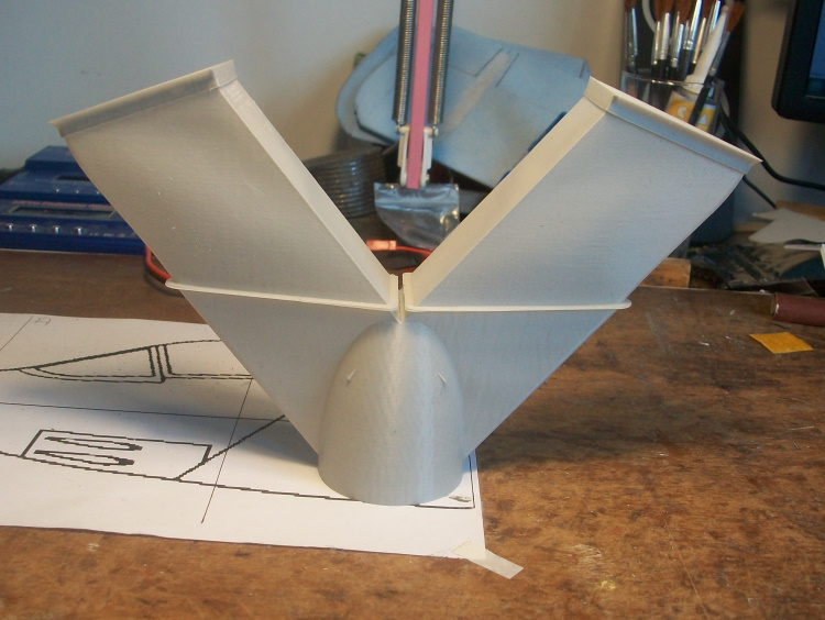
Including the inlet bell mouths it is made up of 5 parts. The large flat areas may need some additional stiffening ribs adding.
The long exhaust duct will most likely also be made up of several sections.
As the total duct will make up about 2/3 of the fuselage length I may adopt the technique I used on the Gnat using the duct as a 'spine' and simply adding the fuselage formers to it. It can then be carefully planked. Only the nose section would be built as before.
Apparently the P1081 used an all moving tail plane so I might consider doing the same. I would avoid the issue from the angled elevator hinge lines.
Thanks: Eric, Klipkopwildlife, Flytilbroke, THE BLACKBIRD
Please Log in or Create an account to join the conversation.
- Quorneng
-
Topic Author
- Offline
- Forum Master
-
Less
More
- Posts: 9436
- Thank you received: 19043
29 Jul 2021 21:23 - 29 Jul 2021 21:24 #3
by Quorneng
Replied by Quorneng on topic P1081 The 'straight through' swept wing Sea Hawk
A test to add a k to the title
An edit to remove the k
An edit to remove the k
Last edit: 29 Jul 2021 21:24 by Quorneng.
Please Log in or Create an account to join the conversation.
- Quorneng
-
Topic Author
- Offline
- Forum Master
-
Less
More
- Posts: 9436
- Thank you received: 19043
30 Jul 2021 21:04 #4
by Quorneng
Replied by Quorneng on topic P1081 The 'straight through' swept wing Sea Hawk
Not much to show. The inlet flat surfaces have stiffeners added.

The ring in front is a test print of two short exhaust tube sections that have been glued together to check they fit.
The actual exhaust tube will be made up of 5 sections each 109 mm long, 4 identical and one modified to fit the rear of the EDF.
I could print fewer longer sections but I am conscious that the duct has to be rigid enough to act as spine to build the fuselage around.
The fuselage side view.
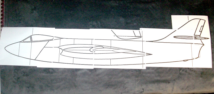
In conjunction with the plan view I will have to work out where the fuselage formers need to be and what shape they are.
One advantage of building over a rigid spine is can check using the Mk1 eyeball the 'line' of the formers and adjust if required before the skin planks go on. Hopefully it leads to a smoother fuselage profile.
The ring in front is a test print of two short exhaust tube sections that have been glued together to check they fit.
The actual exhaust tube will be made up of 5 sections each 109 mm long, 4 identical and one modified to fit the rear of the EDF.
I could print fewer longer sections but I am conscious that the duct has to be rigid enough to act as spine to build the fuselage around.
The fuselage side view.
In conjunction with the plan view I will have to work out where the fuselage formers need to be and what shape they are.
One advantage of building over a rigid spine is can check using the Mk1 eyeball the 'line' of the formers and adjust if required before the skin planks go on. Hopefully it leads to a smoother fuselage profile.
Thanks: Klipkopwildlife
Please Log in or Create an account to join the conversation.
- paul d
-
- Offline
- Forum Veteran
-

Less
More
- Posts: 2074
- Thank you received: 2292
31 Jul 2021 07:23 #5
by paul d
balsa is best.
Replied by paul d on topic P1081 The 'straight through' swept wing Sea Hawk
Nice work...as normal!
balsa is best.
Thanks: Klipkopwildlife
Please Log in or Create an account to join the conversation.
- Quorneng
-
Topic Author
- Offline
- Forum Master
-
Less
More
- Posts: 9436
- Thank you received: 19043
02 Aug 2021 22:55 - 02 Aug 2021 22:57 #6
by Quorneng
Replied by Quorneng on topic P1081 The 'straight through' swept wing Sea Hawk
Still waiting for the EDF to arrive. According to 'tracking' it is now in the country.
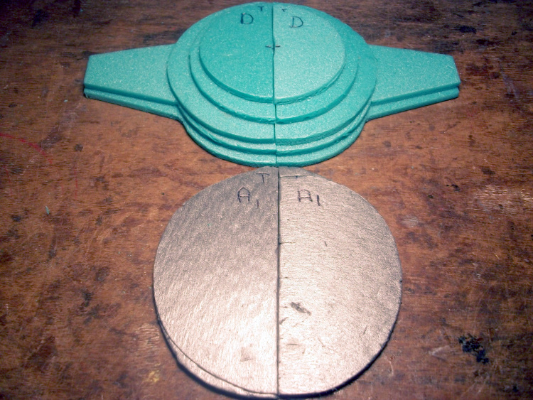
The stack of fuselage formers that will have their centres cut out appropriately to 'surround' the complete duct.
This is sitting on my lap as I type this.
"Noodle" The living embodiment of a 'lap' dog .
The stack of fuselage formers that will have their centres cut out appropriately to 'surround' the complete duct.
This is sitting on my lap as I type this.
"Noodle" The living embodiment of a 'lap' dog .
Last edit: 02 Aug 2021 22:57 by Quorneng.
Thanks: Klipkopwildlife
Please Log in or Create an account to join the conversation.
- Quorneng
-
Topic Author
- Offline
- Forum Master
-
Less
More
- Posts: 9436
- Thank you received: 19043
05 Aug 2021 15:28 - 05 Aug 2021 15:31 #7
by Quorneng
Replied by Quorneng on topic P1081 The 'straight through' swept wing Sea Hawk
At last the 55 mm EDF has arrived.

Typical QX job with the motor a bit 'stuck out the back' and with the motor leads arranged sideways in the air flow. :ohmy: At least with the AOC EDFs the motor wires are contained inside one of the three streamlined bearing support legs.
So spent some time printing fairings for both in front and behind the motor as well as trying to minimise the area of the motor wires.
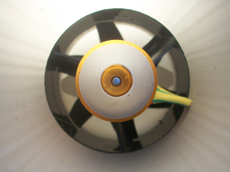
The EDF, minus its bell mouth (it had to be cut off) between the inlet duct and the first of five exhaust sections. Each takes 55 minutes to print. :woohoo:
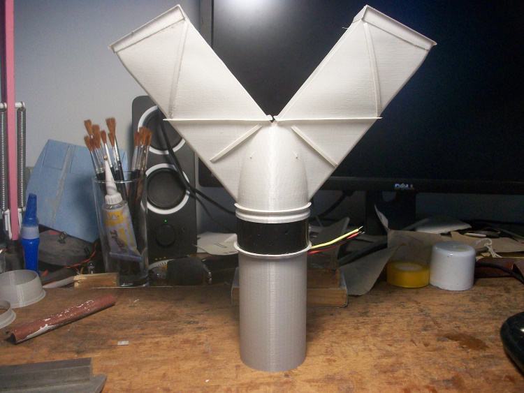
Typical QX job with the motor a bit 'stuck out the back' and with the motor leads arranged sideways in the air flow. :ohmy: At least with the AOC EDFs the motor wires are contained inside one of the three streamlined bearing support legs.
So spent some time printing fairings for both in front and behind the motor as well as trying to minimise the area of the motor wires.
The EDF, minus its bell mouth (it had to be cut off) between the inlet duct and the first of five exhaust sections. Each takes 55 minutes to print. :woohoo:
Last edit: 05 Aug 2021 15:31 by Quorneng.
Thanks: Klipkopwildlife
Please Log in or Create an account to join the conversation.
- paul d
-
- Offline
- Forum Veteran
-
Less
More
- Posts: 2074
- Thank you received: 2292
05 Aug 2021 16:16 #8
by paul d
balsa is best.
Replied by paul d on topic P1081 The 'straight through' swept wing Sea Hawk
Nice work but surely your blocking the cooling airflow through the motor?
balsa is best.
Thanks: Klipkopwildlife
Please Log in or Create an account to join the conversation.
- Quorneng
-
Topic Author
- Offline
- Forum Master
-
Less
More
- Posts: 9436
- Thank you received: 19043
05 Aug 2021 19:12 #9
by Quorneng
Replied by Quorneng on topic P1081 The 'straight through' swept wing Sea Hawk
Paul
Sorry that 'end on' picture is not clear.
It is a truncated cone on the end of the motor.
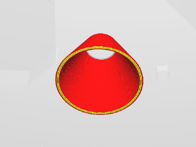
The aperture at the end of the cone has a bigger area than the 6 air inlets at the front of the motor so cooling should not be compromised.
My own view is that the original squared off end to the motor would actually create less 'suction' through the motor than the streamline airflow off the end of the cone. In addition there is less disturbance to the EDF airflow = more thrust.
Likely a waste of time as any improvement will be completely un measurable!
Sorry that 'end on' picture is not clear.
It is a truncated cone on the end of the motor.
The aperture at the end of the cone has a bigger area than the 6 air inlets at the front of the motor so cooling should not be compromised.
My own view is that the original squared off end to the motor would actually create less 'suction' through the motor than the streamline airflow off the end of the cone. In addition there is less disturbance to the EDF airflow = more thrust.
Likely a waste of time as any improvement will be completely un measurable!
Thanks: Eric, Klipkopwildlife
Please Log in or Create an account to join the conversation.
- paul d
-
- Offline
- Forum Veteran
-
Less
More
- Posts: 2074
- Thank you received: 2292
05 Aug 2021 19:40 #10
by paul d
balsa is best.
Replied by paul d on topic P1081 The 'straight through' swept wing Sea Hawk
Oh I see! very clever!
balsa is best.
Thanks: Klipkopwildlife
Please Log in or Create an account to join the conversation.
- Quorneng
-
Topic Author
- Offline
- Forum Master
-
Less
More
- Posts: 9436
- Thank you received: 19043
05 Aug 2021 20:20 #11
by Quorneng
Replied by Quorneng on topic P1081 The 'straight through' swept wing Sea Hawk
The completed but seriously long duct over the fuselage plan.

Given that the EDF is almost exactly where the RR Nene was in the original you can imagine that long duct gave little benefit over the Sea Hawk's much shorter bifurcated one.
I have yet to find out how much extra thrust was actually generated by the after burner installation.
The P1081 did not survive. It crash killing Hawker's test pilot Squadron Leader Wade in April 1951.
I can now start actually building the P1081. :ohmy:
Thanks: Eric, Klipkopwildlife, THE BLACKBIRD, Ralpharr2001
Please Log in or Create an account to join the conversation.
- Quorneng
-
Topic Author
- Offline
- Forum Master
-
Less
More
- Posts: 9436
- Thank you received: 19043
07 Aug 2021 20:29 #12
by Quorneng
Replied by Quorneng on topic P1081 The 'straight through' swept wing Sea Hawk
The first plank goes on, actually there are two, the another is at the back.
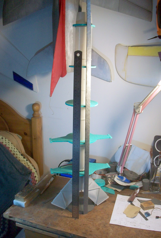
The 2 foot rule gives an indication of the length of each plank.
It has taken quite a bit to get to this stage as just about everything that could go wrong did. I even had to reprint some of the duct.
At least from now on the fuselage will get stronger and stronger.
The 2 foot rule gives an indication of the length of each plank.
It has taken quite a bit to get to this stage as just about everything that could go wrong did. I even had to reprint some of the duct.
At least from now on the fuselage will get stronger and stronger.
Thanks: Eric, Klipkopwildlife, Ralpharr2001
Please Log in or Create an account to join the conversation.
- Quorneng
-
Topic Author
- Offline
- Forum Master
-
Less
More
- Posts: 9436
- Thank you received: 19043
09 Aug 2021 11:31 #13
by Quorneng
Replied by Quorneng on topic P1081 The 'straight through' swept wing Sea Hawk
Rather slow going with such long planks. The XPS is easy enough to bend to shape, its a very gentle curve anyway, but each plank does require quite a bit of sanding to shape.
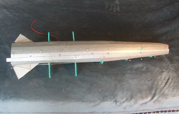
About half done but so far is the easy bit!
In any case before the rear fuselage skin can be completed the fin and tail plane will have to go on so the elevator servo wire can be run through the formers.
About half done but so far is the easy bit!
In any case before the rear fuselage skin can be completed the fin and tail plane will have to go on so the elevator servo wire can be run through the formers.
Thanks: Klipkopwildlife
Please Log in or Create an account to join the conversation.
- Quorneng
-
Topic Author
- Offline
- Forum Master
-
Less
More
- Posts: 9436
- Thank you received: 19043
09 Aug 2021 12:36 - 09 Aug 2021 12:37 #14
by Quorneng
Replied by Quorneng on topic P1081 The 'straight through' swept wing Sea Hawk
Nothing to do with the build but I had not realised how important the concept of the of the Nene engine was to Rolls Royce.
The first Nene ran in early 1945 and it appears the turbine design group that included Stanley Hooker worked out that a 4/5 scale Nene would exactly match the size of the Derwent then in production for the Meteor but would produce 3500 lbs of thrust rather than the 2000 lbs they were struggling to coax out of the Derwent. Although called the Derwent 5 it was actually a completely new engine and gave the 1946 Meteor a genuine 600 mph in service speed.
At 5000 lbs thrust the Nene was in 1945 a powerful and reliable jet engine but the design team proposed an even bigger version at 7000 lbs thrust called the Tay. UK government took no interest but RR had already signed a deal with Pratt & Whitney to licence produce the Nene as the J42 which powered the Grumman Panther.
P&W were very interested in the bigger version, took over the Tay design lead and produced it as the J48 which powered the Grumman Cougar, a swept wing Panther, and the Lockheed Starfire. All of which were produced in considerable numbers.
At that time it seems there really was a "special relationship".
Last edit: 09 Aug 2021 12:37 by Quorneng.
Thanks: Klipkopwildlife
Please Log in or Create an account to join the conversation.
- Quorneng
-
Topic Author
- Offline
- Forum Master
-
Less
More
- Posts: 9436
- Thank you received: 19043
10 Aug 2021 22:52 - 10 Aug 2021 22:54 #15
by Quorneng
Replied by Quorneng on topic P1081 The 'straight through' swept wing Sea Hawk
Slowly moving on.
The wing root fairings added, at least on the top side.
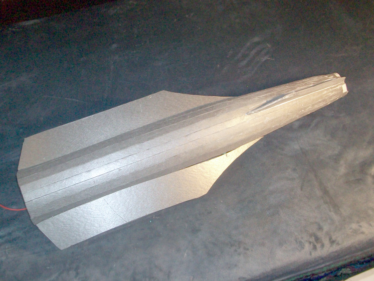
At least on the top surface as the under side will be left open until all the servos are in.
The fin base that supports the tail plane.
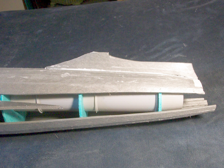
With a streamline section it is made up of two XPS layers so is 10 mm thick.
Apart from being a good fit in the fuselage top skin it also descends down and is glued to the top surface of the duct.
The tail plane as well as the rest of the fin will be made from two skins of 3 mm Depron.
The wing root fairings added, at least on the top side.
At least on the top surface as the under side will be left open until all the servos are in.
The fin base that supports the tail plane.
With a streamline section it is made up of two XPS layers so is 10 mm thick.
Apart from being a good fit in the fuselage top skin it also descends down and is glued to the top surface of the duct.
The tail plane as well as the rest of the fin will be made from two skins of 3 mm Depron.
Last edit: 10 Aug 2021 22:54 by Quorneng.
Thanks: Klipkopwildlife, paul d
Please Log in or Create an account to join the conversation.
Time to create page: 1.465 seconds