
- Posts: 12
- Thank you received: 14
1st time builder-Dumas kit 210 Ford Trimotor Need help with wire landing gear
- MiamiMan
- Topic Author
- Offline
- New Member
-

Less
More
30 Apr 2021 20:26 #1
by MiamiMan
1st time builder-Dumas kit 210 Ford Trimotor Need help with wire landing gear was created by MiamiMan
Hello, I live in Miami, Florida, and even though it's supposed to be a tropical paradise, this part of building this kit Dumas 210 Ford Trimotor) is making me crazy.
I can't for the life of me figure out how Wire A is supposed to fit, not to mention wire B.
It says to cover all parts and then cement the wing onto the fuselage, and THEN drill a hole into the wing for Wire B.
11/16 in from the dihedral break (which I can't see) Am I supposed to drill through the tissue??
At this point I am completely befuddled and could use a helping hand.
Thanks.
Thanks: Klipkopwildlife
Please Log in or Create an account to join the conversation.
- Eric
-

- Offline
- Moderator
-

Less
More
- Posts: 13726
- Thank you received: 14470
30 Apr 2021 21:03 #2
by Eric
if you are calm and collected when all about you are going berserk - you've missed something important!
Replied by Eric on topic 1st time builder-Dumas kit 210 Ford Trimotor Need help with wire landing gear
Answering this could be difficult, because the majority of active readers of this group are in the UK.
Myself, I've never seen any Dumas kit, but reading between the lines, I would hazard a guess that this model is a pretty small free-flight one.
The best I can suggest is that you do a computer search for a full-size Tri, and see if you can see where the wires go, such as -
www.google.com/search?q=ford+tri-motor+i...imgrc=zVkzvwkqRLOyfM
if you are calm and collected when all about you are going berserk - you've missed something important!
Thanks: Klipkopwildlife
Please Log in or Create an account to join the conversation.
- Quorneng
-

- Offline
- Forum Master
-

Less
More
- Posts: 9436
- Thank you received: 19043
30 Apr 2021 22:12 - 30 Apr 2021 22:12 #3
by Quorneng
Replied by Quorneng on topic 1st time builder-Dumas kit 210 Ford Trimotor Need help with wire landing gear
It is indeed small. A peanut scale (13" span) Tri Motor!

The only way we might be able to help is if you could post a decent image of the plans or someone on here buys one!
The only way we might be able to help is if you could post a decent image of the plans or someone on here buys one!
Last edit: 30 Apr 2021 22:12 by Quorneng.
Thanks: Klipkopwildlife
Please Log in or Create an account to join the conversation.
- MiamiMan
- Topic Author
- Offline
- New Member
-
Less
More
- Posts: 12
- Thank you received: 14
01 May 2021 13:13 - 02 May 2021 08:54 #4
by MiamiMan
Replied by MiamiMan on topic 1st time builder-Dumas kit 210 Ford Trimotor Need help with wire landing gear
Thank you. Here are the instructions. Note that page 3, item 3 is where i get confused as to how to bend wire A.
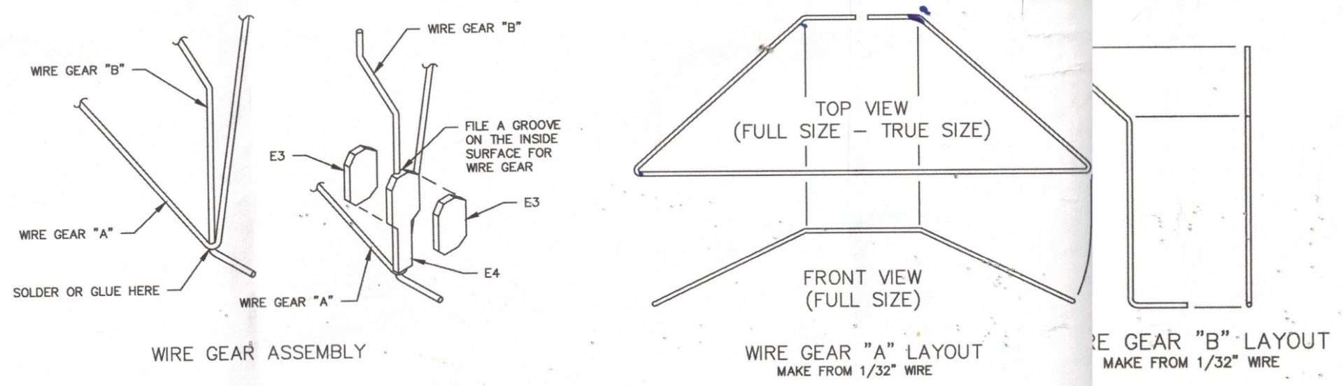
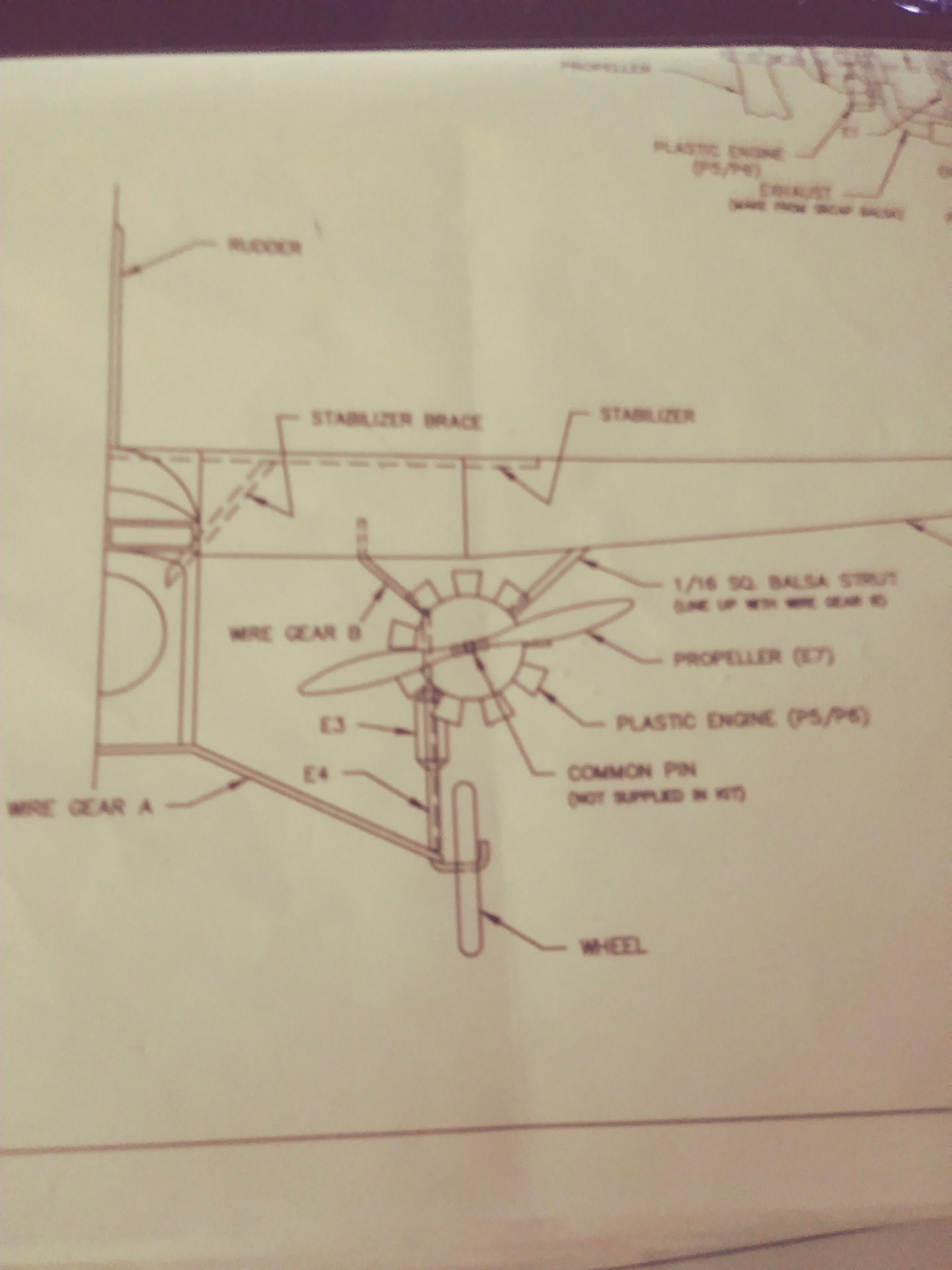


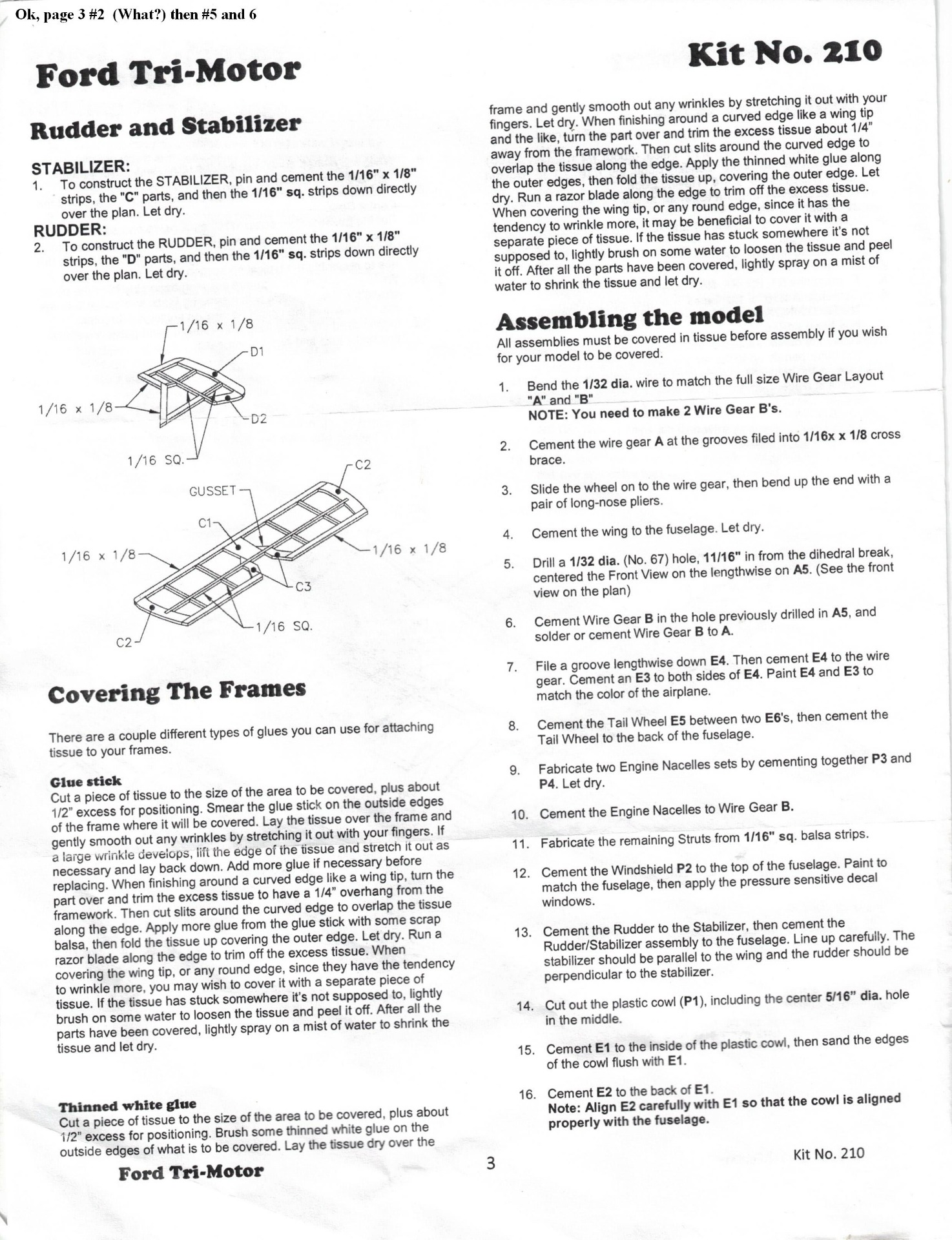
Pictures inserted.
Pictures inserted.
Last edit: 02 May 2021 08:54 by Klipkopwildlife. Reason: insert pics
Thanks: Klipkopwildlife
Please Log in or Create an account to join the conversation.
- MiamiMan
- Topic Author
- Offline
- New Member
-
Less
More
- Posts: 12
- Thank you received: 14
01 May 2021 13:20 #5
by MiamiMan
Replied by MiamiMan on topic 1st time builder-Dumas kit 210 Ford Trimotor Need help with wire landing gear
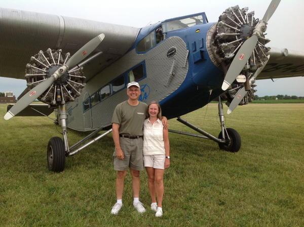
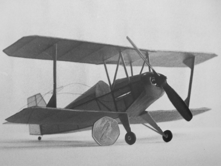
Good view of landing gear, but how do I create this structure with wire A and wire B
Thanks: Klipkopwildlife
Please Log in or Create an account to join the conversation.
- MiamiMan
- Topic Author
- Offline
- New Member
-
Less
More
- Posts: 12
- Thank you received: 14
01 May 2021 16:39 #6
by MiamiMan
Replied by MiamiMan on topic 1st time builder-Dumas kit 210 Ford Trimotor Need help with wire landing gear
Which supplier would you recommend that has clearer instructions?
Please Log in or Create an account to join the conversation.
- Quorneng
-
- Offline
- Forum Master
-
Less
More
- Posts: 9436
- Thank you received: 19043
01 May 2021 16:43 - 01 May 2021 16:47 #7
by Quorneng
Replied by Quorneng on topic 1st time builder-Dumas kit 210 Ford Trimotor Need help with wire landing gear
These might help.
I made the A&B parts full size but out of easy to bend copper wire.
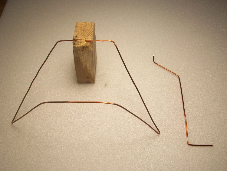

You will obviously need two Bs, one for each side.
They are joined like this. I would suggest solder if possible.
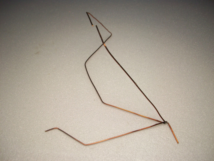
Note B and the front strut lie parallel to each other which make assembly a bit easier.
Finished, on one side, the wire should look like this.

I don't know how the undercarriage parts are actually fixed to the air frame.
Peanut scale is a bit small for me.
My only attempt was an Andreason BA4b converted to electric well over 50 years ago.
I made the A&B parts full size but out of easy to bend copper wire.
You will obviously need two Bs, one for each side.
They are joined like this. I would suggest solder if possible.
Note B and the front strut lie parallel to each other which make assembly a bit easier.
Finished, on one side, the wire should look like this.
I don't know how the undercarriage parts are actually fixed to the air frame.
Peanut scale is a bit small for me.
My only attempt was an Andreason BA4b converted to electric well over 50 years ago.
Last edit: 01 May 2021 16:47 by Quorneng.
Thanks: Eric, Klipkopwildlife, MiamiMan
Please Log in or Create an account to join the conversation.
- MiamiMan
- Topic Author
- Offline
- New Member
-
Less
More
- Posts: 12
- Thank you received: 14
01 May 2021 16:46 #8
by MiamiMan
Replied by MiamiMan on topic 1st time builder-Dumas kit 210 Ford Trimotor Need help with wire landing gear
Quorneng, if you posted pictures, I cannot see them, just "You do not have permissions to access this page"
Thanks: Klipkopwildlife
Please Log in or Create an account to join the conversation.
- Quorneng
-
- Offline
- Forum Master
-
Less
More
- Posts: 9436
- Thank you received: 19043
01 May 2021 16:48 #9
by Quorneng
Replied by Quorneng on topic 1st time builder-Dumas kit 210 Ford Trimotor Need help with wire landing gear
Sorry! now fixed
Thanks: MiamiMan
Please Log in or Create an account to join the conversation.
- MiamiMan
- Topic Author
- Offline
- New Member
-
Less
More
- Posts: 12
- Thank you received: 14
01 May 2021 17:50 #10
by MiamiMan
Replied by MiamiMan on topic 1st time builder-Dumas kit 210 Ford Trimotor Need help with wire landing gear
Yes, i see them now. So even though instruction 3 says to put the wheel on wire A, it goes on wire B in #6?
Thank you for going out of your way to take pics of your work.
Thank you for going out of your way to take pics of your work.
Thanks: Klipkopwildlife
Please Log in or Create an account to join the conversation.
- MiamiMan
- Topic Author
- Offline
- New Member
-
Less
More
- Posts: 12
- Thank you received: 14
01 May 2021 19:03 - 02 May 2021 08:58 #11
by MiamiMan
Replied by MiamiMan on topic 1st time builder-Dumas kit 210 Ford Trimotor Need help with wire landing gear
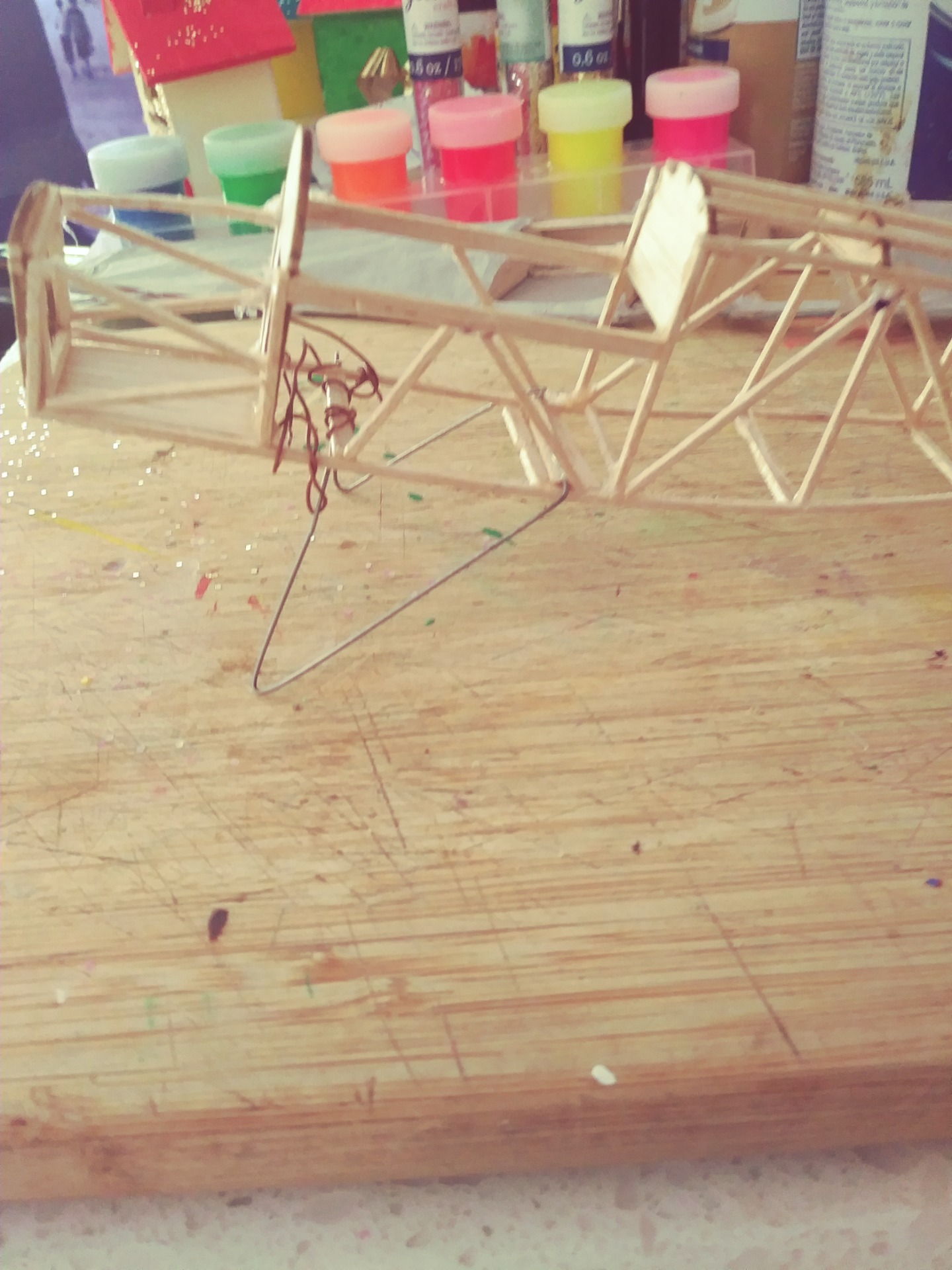
My temporarily placed wire gear A.
MM, you need to remember to press 'insert' otherwise we only get the thumbnails.
MM, you need to remember to press 'insert' otherwise we only get the thumbnails.
Last edit: 02 May 2021 08:58 by Klipkopwildlife. Reason: insert pics
Thanks: Klipkopwildlife, Quorneng
Please Log in or Create an account to join the conversation.
- Eric
-
- Offline
- Moderator
-
Less
More
- Posts: 13726
- Thank you received: 14470
01 May 2021 21:17 #12
by Eric
if you are calm and collected when all about you are going berserk - you've missed something important!
Replied by Eric on topic 1st time builder-Dumas kit 210 Ford Trimotor Need help with wire landing gear
You are missing a step out when you send pic's, so all we see are the thumbnails.
There's a tutorial on here somewhere, but right now I don't have time to look for it, I'm in the middle of cooking the evening meal!
There's a tutorial on here somewhere, but right now I don't have time to look for it, I'm in the middle of cooking the evening meal!
if you are calm and collected when all about you are going berserk - you've missed something important!
Thanks: Klipkopwildlife, MiamiMan
Please Log in or Create an account to join the conversation.
- MiamiMan
- Topic Author
- Offline
- New Member
-
Less
More
- Posts: 12
- Thank you received: 14
01 May 2021 22:29 #13
by MiamiMan

Replied by MiamiMan on topic 1st time builder-Dumas kit 210 Ford Trimotor Need help with wire landing gear
Thanks: Eric, Klipkopwildlife, Quorneng
Please Log in or Create an account to join the conversation.
- MiamiMan
- Topic Author
- Offline
- New Member
-
Less
More
- Posts: 12
- Thank you received: 14
01 May 2021 22:29 #14
by MiamiMan
Replied by MiamiMan on topic 1st time builder-Dumas kit 210 Ford Trimotor Need help with wire landing gear
Thank you. Didn't realize there was an extra step. Enjoy your dinner!
Thanks: Eric, Klipkopwildlife
Please Log in or Create an account to join the conversation.
- Quorneng
-
- Offline
- Forum Master
-
Less
More
- Posts: 9436
- Thank you received: 19043
02 May 2021 12:33 #15
by Quorneng
Replied by Quorneng on topic 1st time builder-Dumas kit 210 Ford Trimotor Need help with wire landing gear
MiamiMan
Wow! That looks like an immensely thick (scale?) wing section.
At very small sizes the normal rule is that a thin wing section reduces drag well in excess of the loss in lift. One reason why 'shockies' with their 'flat plate' wings fly so well.
Wow! That looks like an immensely thick (scale?) wing section.
At very small sizes the normal rule is that a thin wing section reduces drag well in excess of the loss in lift. One reason why 'shockies' with their 'flat plate' wings fly so well.
Thanks: Eric, Klipkopwildlife
Please Log in or Create an account to join the conversation.
Time to create page: 1.050 seconds