
- Posts: 809
- Thank you received: 2067
×
Flying models without a radio
Keil Kraft Piper Family Cruiser
- Squirrelnet
- Topic Author
- Offline
- Elite Member
-

Less
More
01 May 2017 18:15 #1
by Squirrelnet
Keil Kraft Piper Family Cruiser was created by Squirrelnet
With summer approaching and the thought of warm calm days  I thought I would build a nice easy flyer.
I have a couple of Gasparin GM300's that need airframes so I thought why not use one of them and have a go at a larger outdoor scale model. If I can trim it for a reliable tight circuit them maybe indoors too
My GM300 powered 'Skyscraper' , a vintage 1937 US design by Leon Shulman built to half size is great flyer at 30" span. It goes so well I've fitted a D/T to it after it hooked some lift and escaped the airfield at Middle Wallop. Infact I like it so much its my avatar.
I have scaled the Piper up a bit to give me a 28" version which given it's broader chord wings should give me a model of about the same size as the Skyscraper. I have to credit Andy with the inspiration as his rubber version looks and flies nicely and I'm a sucker for a yellow aeroplane

I'm thinking I will install the engine inverted as it almost fits with just small bit of CO2 pipe poking out. Logic would dictate a side mounted fitting but then the little bit of pipe sticks out the side ,I think its less noticeable this way.
Not sure about down thrust I'll have to look at other similar designs but I'd guess about 3 deg ??????
The fuselage I have upgraded to 3/32" sq rather then the original 1/16" and I'll add some extra 1/16 sheet around the nose and undercarriage mount so I can mount gas tank near the CG
I think have enough wood etc to build it which is even better , the only thing I don't have are some 1 1/4" wheels so I might try and turn some from balsa on drill. Never done it before but it works in my head![[badass]](/media/kunena/emoticons/bad_boys_20.gif "[badass]")

I thought I would build a nice easy flyer.I have a couple of Gasparin GM300's that need airframes so I thought why not use one of them and have a go at a larger outdoor scale model. If I can trim it for a reliable tight circuit them maybe indoors too
My GM300 powered 'Skyscraper' , a vintage 1937 US design by Leon Shulman built to half size is great flyer at 30" span. It goes so well I've fitted a D/T to it after it hooked some lift and escaped the airfield at Middle Wallop. Infact I like it so much its my avatar.
I have scaled the Piper up a bit to give me a 28" version which given it's broader chord wings should give me a model of about the same size as the Skyscraper. I have to credit Andy with the inspiration as his rubber version looks and flies nicely and I'm a sucker for a yellow aeroplane
I'm thinking I will install the engine inverted as it almost fits with just small bit of CO2 pipe poking out. Logic would dictate a side mounted fitting but then the little bit of pipe sticks out the side ,I think its less noticeable this way.
Not sure about down thrust I'll have to look at other similar designs but I'd guess about 3 deg ??????
The fuselage I have upgraded to 3/32" sq rather then the original 1/16" and I'll add some extra 1/16 sheet around the nose and undercarriage mount so I can mount gas tank near the CG
I think have enough wood etc to build it which is even better , the only thing I don't have are some 1 1/4" wheels so I might try and turn some from balsa on drill. Never done it before but it works in my head
Thanks: Klipkopwildlife, Quorneng, THE BLACKBIRD, old fart, Monz, one tenor, boz, Firewood and 2 other people also said thanks.
Please Log in or Create an account to join the conversation.
- Nigel
- Offline
- Elite Member
-
Less
More
- Posts: 204
- Thank you received: 405
03 May 2017 00:05 - 03 May 2017 00:10 #2
by Nigel
Replied by Nigel on topic Keil Kraft Piper Family Cruiser
Cool
Be interesting to see how the G300 matches the airframe.
Will you use the kit/plan airfoil profile? I have a (possibly irrational) hatred of the pointy front/ fat 60% chord section that is quite prevalent in certain kits. I think it will cause a sharp stall transition, but that's based more on opinion than evidence so I should know better. Can I get away with "it just looks wrong!"?
Be interesting to see how the G300 matches the airframe.
Will you use the kit/plan airfoil profile? I have a (possibly irrational) hatred of the pointy front/ fat 60% chord section that is quite prevalent in certain kits. I think it will cause a sharp stall transition, but that's based more on opinion than evidence so I should know better. Can I get away with "it just looks wrong!"?
Last edit: 03 May 2017 00:10 by Nigel.
Thanks: boz
Please Log in or Create an account to join the conversation.
- Quorneng
-

- Offline
- Forum Master
-

Less
More
- Posts: 10058
- Thank you received: 19043
03 May 2017 11:20 #3
by Quorneng
Replied by Quorneng on topic Keil Kraft Piper Family Cruiser
My own experience with such flat bottomed 'sharp pointy' air foils is it all depends on size. The bigger the chord the more the section matters.
Things like the boundary layer thickness and viscosity do not scale so they have a much greater influence at small sizes, disproportionately increasing drag and blurring the point of airflow separation.
My own 'rule of thumb' is that around a 3" chord the wing thickness become the more important factor than its actual section.
Things like the boundary layer thickness and viscosity do not scale so they have a much greater influence at small sizes, disproportionately increasing drag and blurring the point of airflow separation.
My own 'rule of thumb' is that around a 3" chord the wing thickness become the more important factor than its actual section.
Thanks: boz, Firewood, Nigel
Please Log in or Create an account to join the conversation.
- Squirrelnet
- Topic Author
- Offline
- Elite Member
-
Less
More
- Posts: 809
- Thank you received: 2067
04 May 2017 07:09 #4
by Squirrelnet
Replied by Squirrelnet on topic Keil Kraft Piper Family Cruiser
Had not thought of changing the airfoil. The model was original 21" and is now 28:" so not a massive increase (130%). I Was hoping it would keep the nicely flying characteristics seen in Andy's rubber version
Thanks: boz
Please Log in or Create an account to join the conversation.
- Ex-Member
- Visitor
-

04 May 2017 08:57 - 04 May 2017 09:14 #5
by Ex-Member
Replied by Ex-Member on topic Keil Kraft Piper Family Cruiser
It depends what you want the model for, Chris. If it's for top rate competition, then you'd need to alter a lot of things as well as the wing section, if it's for sports flying/experimentation, then leave it as is.
Personally, I'd go for the latter. If you change the section, you may have to change some of the structure to suit....and then you'll have to change something else to make it all fit...and so on. From experience, the section doesn't seem to matter much when scaling up the KK and Veron models, they all seem to fly well with what they've got.
The only change I would consider is to make the wings removable. The span will be rather large, so the moment of any tip impact on the wing root will be excessive. I used 1/4" balsa stub dowels successfully on an Earl Stahl Taylorcraft (32" span) which I posted details of a few years ago. The wing is held in position by a light rubber band and flight loads, the dihedral is maintained with the struts - wire into tube at the wing end and stronger rubber bands through the fuselage at the root. The wing can flex in any direction in the inevitable hard arrival. The same config might help:
www.aeromodellers.co.uk/forum/free-fligh...ff-scale-model#44383
The thread also has details of 1/32" wire dowel fixings, which may also help.
I'll bring the Taylorcraft to Old Warden next weekend if you want to have a look at it.
(PS: if you went to the thread and the pics weren't there, try again. I've reloaded them)
Personally, I'd go for the latter. If you change the section, you may have to change some of the structure to suit....and then you'll have to change something else to make it all fit...and so on. From experience, the section doesn't seem to matter much when scaling up the KK and Veron models, they all seem to fly well with what they've got.
The only change I would consider is to make the wings removable. The span will be rather large, so the moment of any tip impact on the wing root will be excessive. I used 1/4" balsa stub dowels successfully on an Earl Stahl Taylorcraft (32" span) which I posted details of a few years ago. The wing is held in position by a light rubber band and flight loads, the dihedral is maintained with the struts - wire into tube at the wing end and stronger rubber bands through the fuselage at the root. The wing can flex in any direction in the inevitable hard arrival. The same config might help:
www.aeromodellers.co.uk/forum/free-fligh...ff-scale-model#44383
The thread also has details of 1/32" wire dowel fixings, which may also help.
I'll bring the Taylorcraft to Old Warden next weekend if you want to have a look at it.
(PS: if you went to the thread and the pics weren't there, try again. I've reloaded them)
Last edit: 04 May 2017 09:14 by Ex-Member.
Please Log in or Create an account to join the conversation.
- Squirrelnet
- Topic Author
- Offline
- Elite Member
-
Less
More
- Posts: 809
- Thank you received: 2067
04 May 2017 20:08 #6
by Squirrelnet
Replied by Squirrelnet on topic Keil Kraft Piper Family Cruiser
Thanks for the link to the wing fixing Andy. Funnily enough I was thinking of something similar but yours looks much neater and better thought out than the one in my head so I'll do something similar.
I won't change the airfoil I was hoping for a quick build anyway, in fact I have next week off and had a mad idea to knock one together for the Old Warden weekend, not that I don't have enough to fly so.. er ...watch this space. The model is not really for competition, certainly not serious competition but lets see if I can get it to fly nicely first. It would be nice to see the Taylorcraft anyway and obviously I may not get there with the build... is there a modelling equivalent to 'your eyes are bigger than your stomach ?'
Looking forward to the Mayfly fingers crossed for some calm weather. Last September my single chanel rc assist Vic Speed Coquette ended up flying backwards the wind was so strong. I filled it up for one last flight, climbed to good height ok but the wind was a lot stronger up there and all I could do is hold it into wind and watch disappear off the airfield backwards !!! on reflection I should have spun out to a lower level to get out of wind...oh hindsight.

I won't change the airfoil I was hoping for a quick build anyway, in fact I have next week off and had a mad idea to knock one together for the Old Warden weekend, not that I don't have enough to fly so.. er ...watch this space.
The model is not really for competition, certainly not serious competition but lets see if I can get it to fly nicely first. It would be nice to see the Taylorcraft anyway and obviously I may not get there with the build... is there a modelling equivalent to 'your eyes are bigger than your stomach ?'Looking forward to the Mayfly fingers crossed for some calm weather. Last September my single chanel rc assist Vic Speed Coquette ended up flying backwards the wind was so strong. I filled it up for one last flight, climbed to good height ok but the wind was a lot stronger up there and all I could do is hold it into wind and watch disappear off the airfield backwards !!! on reflection I should have spun out to a lower level to get out of wind...oh hindsight.
Thanks: Klipkopwildlife, Ex-Member, one tenor, boz, Firewood, Nigel
Please Log in or Create an account to join the conversation.
- Squirrelnet
- Topic Author
- Offline
- Elite Member
-
Less
More
- Posts: 809
- Thank you received: 2067
06 May 2017 18:24 - 06 May 2017 18:27 #7
by Squirrelnet
Replied by Squirrelnet on topic Keil Kraft Piper Family Cruiser
Hopefully I have broken the back of the project this afternoon and I now have a basic fuselage with the difficult knock off wing attachment and engine mountings complete
The fuselage starts as a basic box section
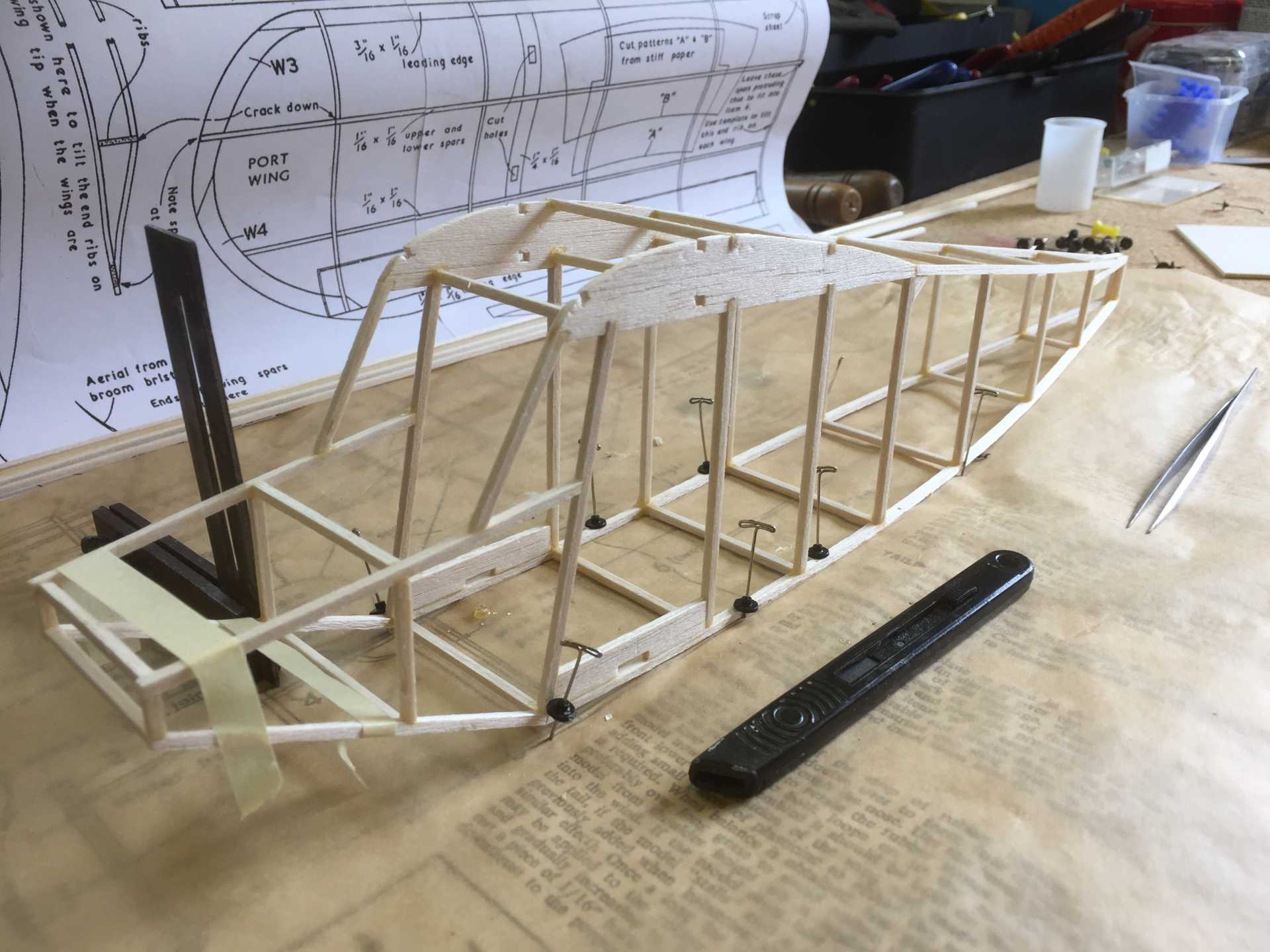
It has been somewhat strengthened from the original KK plan and now has a 1/32" ply / 3/32" balsa former for the undercarriage and Co2 tank to attach to and will be 1/16 sheet box section up to the nose block
The wings will be knock off and are located by rounded 1/4" dowels retained by a small elastic band attached to hooks on the root rib and concealed in a paper tube. The dihedral will be set by the struts which will be located in slots in the fuselage and held by another small band all very much thanks to looking at Andy's thread on Knock off wings.
The card covering on top of the centre section will be replaced by 1/32" sheeting to cope with the wing mounting stresses. The wing root and fuselage wing section are faced with 1/32" ply. I wanted to use 1/64" but I can't find any !!! must have used it all and the sheeting will continue 1 bay back from the undercarriage former to spread the load. Weight is around 50 g but most of that is the engine. Aiming for something a bit over 100g as a flying weight
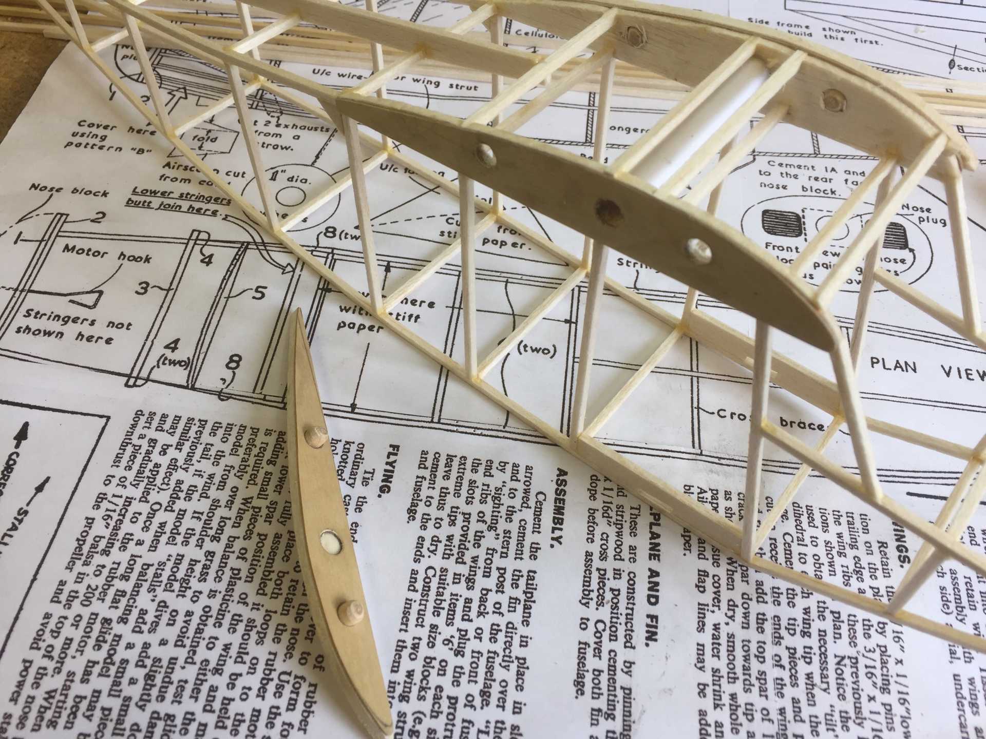
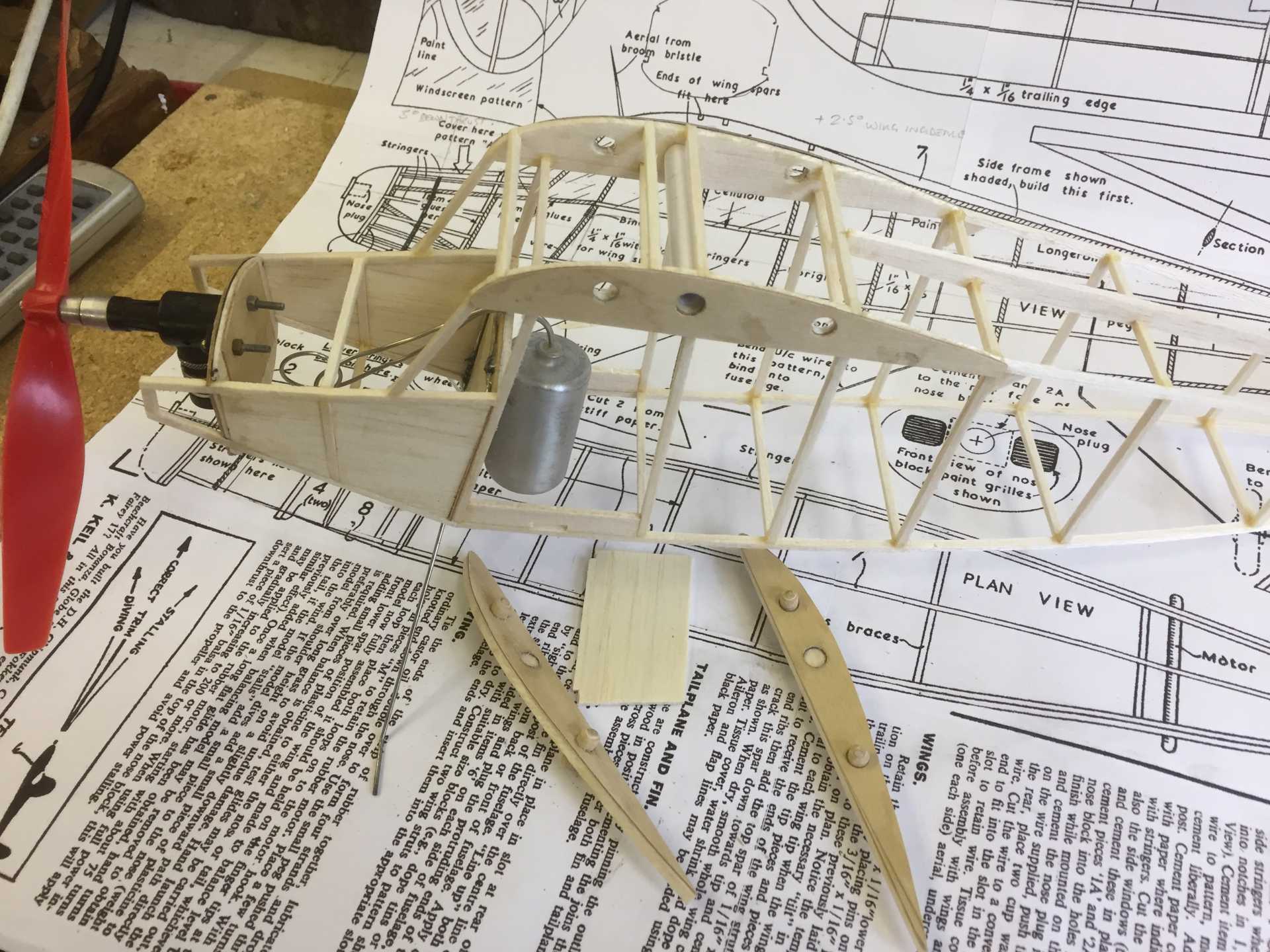
Engine is built in with 3 deg down thrust and 2 deg right thrust which is my usual guess. I'll make the nose block removable with magnet fixing so I can get at the engine for trim adjustments and lubrication and continue the sheet infil upto it.

The CO2 tank is little ahead of the expected CG but any further back and I feared it would need so much extra structure to support it the gain of putting it nearer the CG would be lost
The fuselage starts as a basic box section
It has been somewhat strengthened from the original KK plan and now has a 1/32" ply / 3/32" balsa former for the undercarriage and Co2 tank to attach to and will be 1/16 sheet box section up to the nose block
The wings will be knock off and are located by rounded 1/4" dowels retained by a small elastic band attached to hooks on the root rib and concealed in a paper tube. The dihedral will be set by the struts which will be located in slots in the fuselage and held by another small band all very much thanks to looking at Andy's thread on Knock off wings.
The card covering on top of the centre section will be replaced by 1/32" sheeting to cope with the wing mounting stresses. The wing root and fuselage wing section are faced with 1/32" ply. I wanted to use 1/64" but I can't find any !!! must have used it all and the sheeting will continue 1 bay back from the undercarriage former to spread the load. Weight is around 50 g but most of that is the engine. Aiming for something a bit over 100g as a flying weight
Engine is built in with 3 deg down thrust and 2 deg right thrust which is my usual guess. I'll make the nose block removable with magnet fixing so I can get at the engine for trim adjustments and lubrication and continue the sheet infil upto it.
The CO2 tank is little ahead of the expected CG but any further back and I feared it would need so much extra structure to support it the gain of putting it nearer the CG would be lost
Last edit: 06 May 2017 18:27 by Squirrelnet.
Thanks: Klipkopwildlife, Quorneng, THE BLACKBIRD, Ex-Member, Monz, boz, Firewood, Mike Rolls, Nigel
Please Log in or Create an account to join the conversation.
- Squirrelnet
- Topic Author
- Offline
- Elite Member
-
Less
More
- Posts: 809
- Thank you received: 2067
07 May 2017 18:48 - 07 May 2017 18:51 #8
by Squirrelnet
Replied by Squirrelnet on topic Keil Kraft Piper Family Cruiser
Still got the wings, tail, struts and wheels to make but looking like a possible for the Mayfly if I can keep this up.
The front former I have done in 1/32 ply to increase its crash resistance and the nose section is in 1/16" balsa to create an open box section to give some strength to the engine mount.
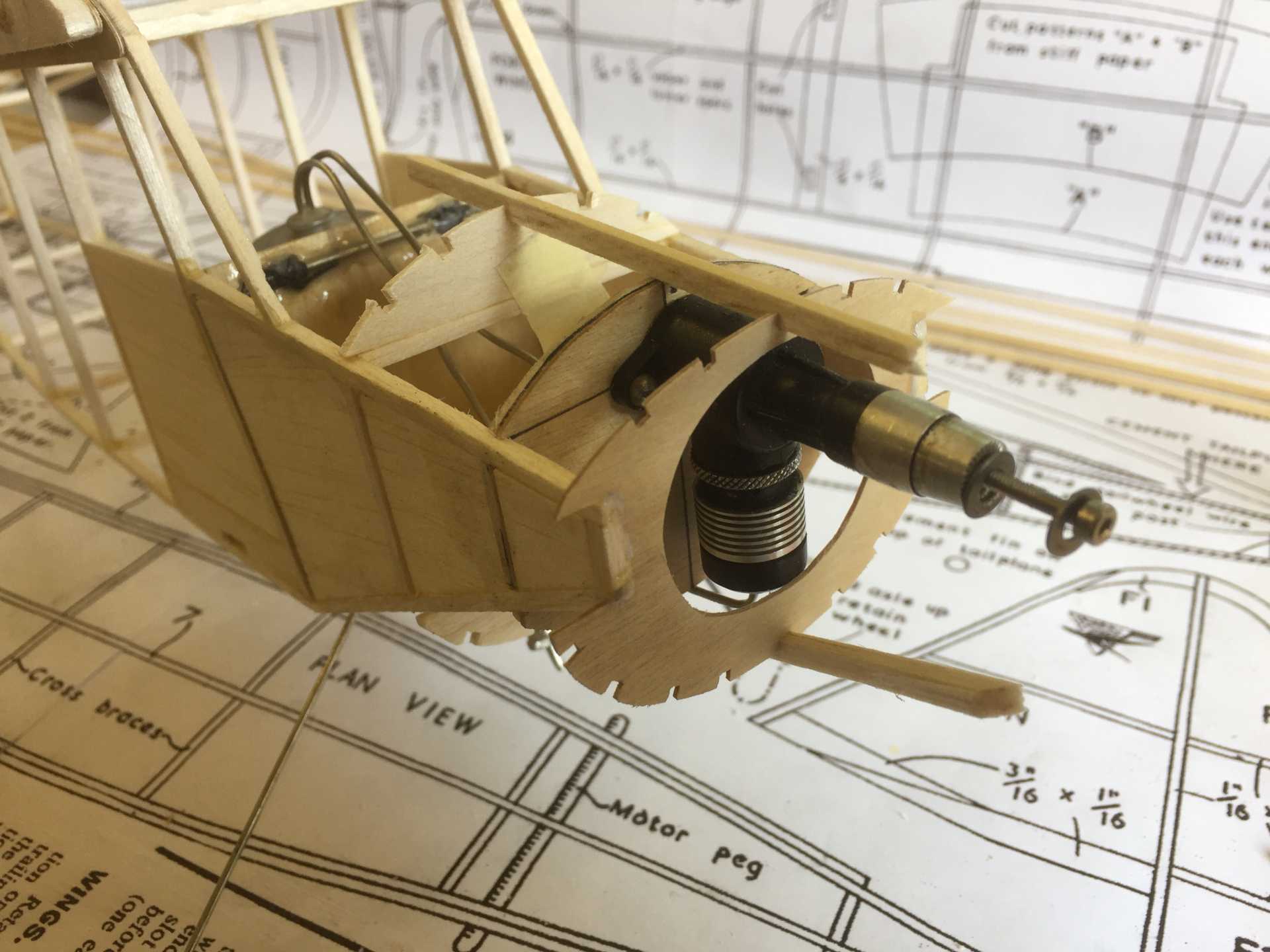
I've made the engine mount fit inside the stringer structure of the nose using the sheeting to locate it as it makes it much easier to build
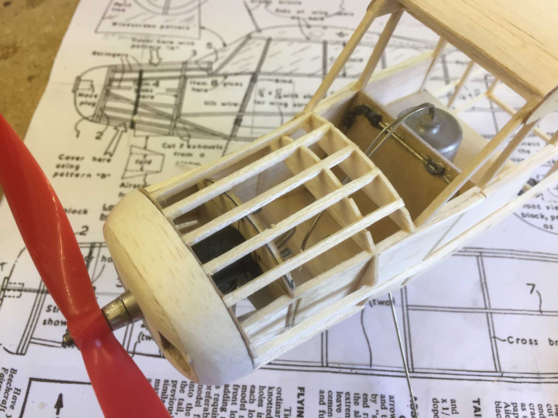
Roughly carved the nose block which is held on by cocktail stick dowels and magnets , I'll have another go at sanding it tomorrow
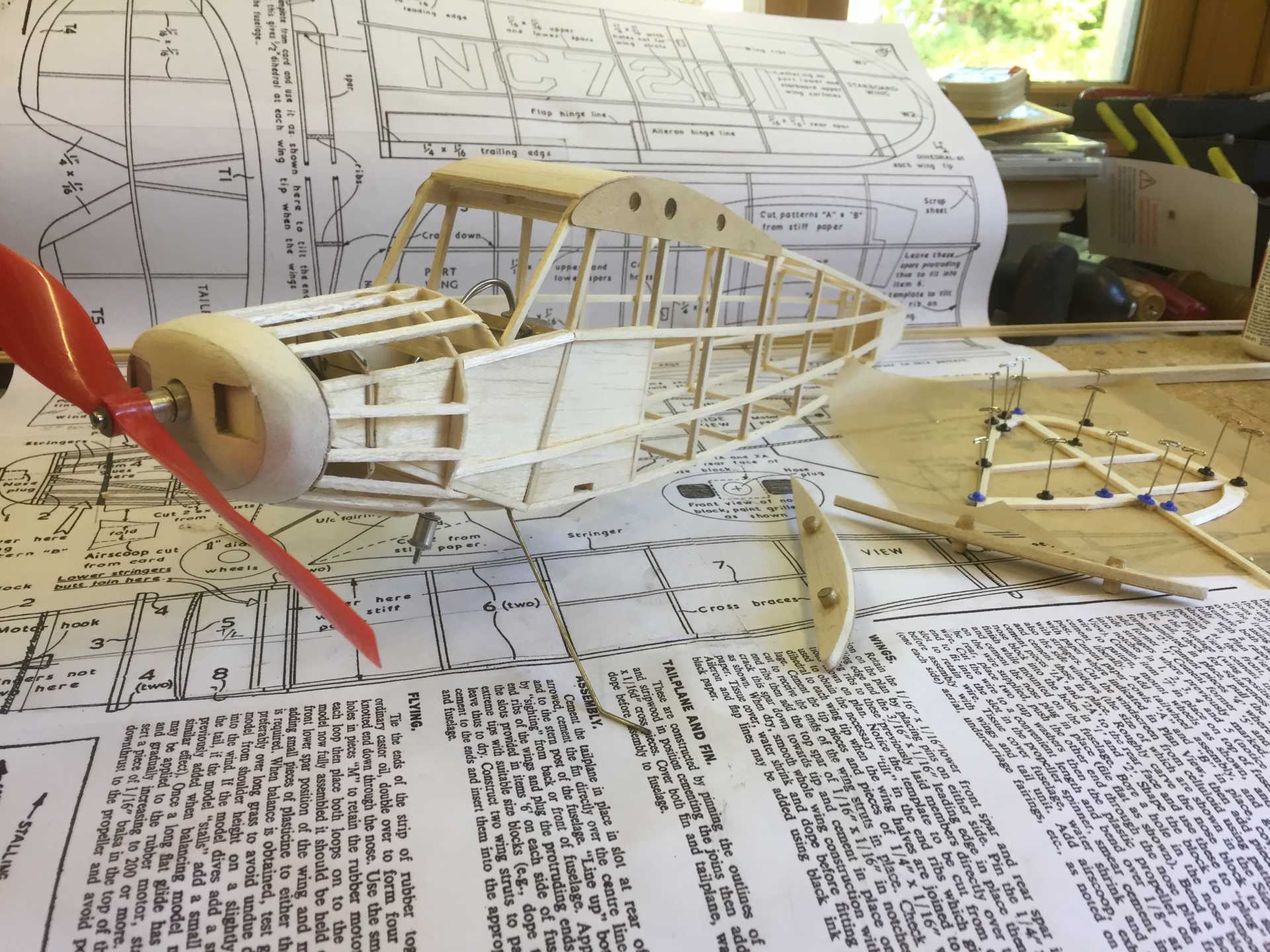
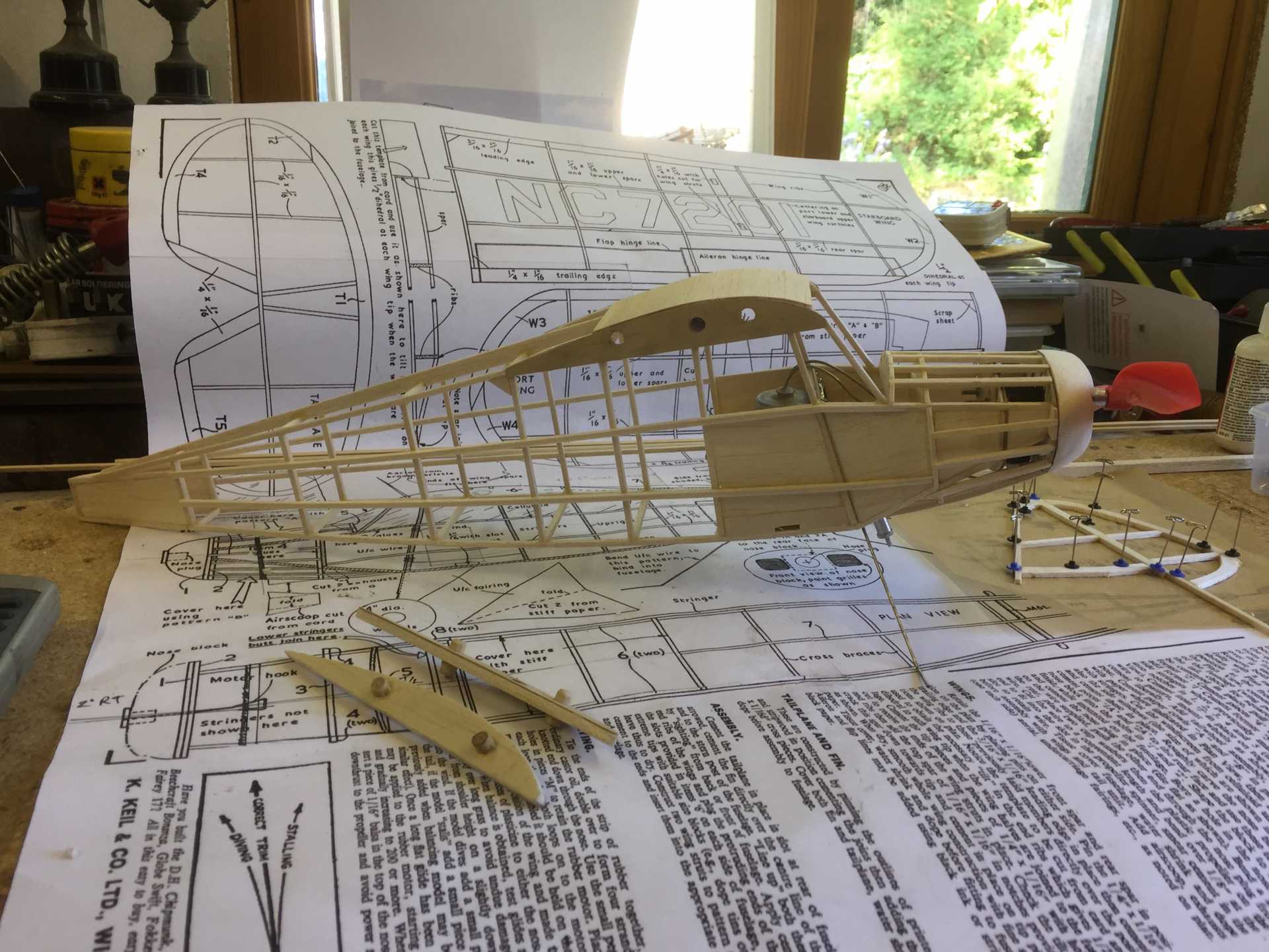
The front former I have done in 1/32 ply to increase its crash resistance and the nose section is in 1/16" balsa to create an open box section to give some strength to the engine mount.
I've made the engine mount fit inside the stringer structure of the nose using the sheeting to locate it as it makes it much easier to build
Roughly carved the nose block which is held on by cocktail stick dowels and magnets , I'll have another go at sanding it tomorrow
Last edit: 07 May 2017 18:51 by Squirrelnet.
Thanks: Klipkopwildlife, Quorneng, Ex-Member, boz, Firewood, Nigel
Please Log in or Create an account to join the conversation.
- Ex-Member
- Visitor
-
07 May 2017 19:28 #9
by Ex-Member
Replied by Ex-Member on topic Keil Kraft Piper Family Cruiser
What a wonderful build sir.
nice looking model as well.
hopefully see it flying at old warden soon then.
Tony B
nice looking model as well.
hopefully see it flying at old warden soon then.
Tony B
Please Log in or Create an account to join the conversation.
- Ex-Member
- Visitor
-
07 May 2017 19:40 #10
by Ex-Member
Replied by Ex-Member on topic Keil Kraft Piper Family Cruiser
That's looking good Chris, well done!

Please Log in or Create an account to join the conversation.
- Squirrelnet
- Topic Author
- Offline
- Elite Member
-
Less
More
- Posts: 809
- Thank you received: 2067
07 May 2017 19:50 - 07 May 2017 19:52 #11
by Squirrelnet
Replied by Squirrelnet on topic Keil Kraft Piper Family Cruiser
Thanks Andy It's a nice one build
Tony , perhaps see you there?
Tony , perhaps see you there?
Last edit: 07 May 2017 19:52 by Squirrelnet.
Please Log in or Create an account to join the conversation.
- Firewood
-

- Offline
- Elite Member
-
Less
More
- Posts: 282
- Thank you received: 268
08 May 2017 08:38 #12
by Firewood
I'm so clever that sometimes I don't understand a single word of what I'm saying.
Replied by Firewood on topic Keil Kraft Piper Family Cruiser
Very good,looking foward to seeing what colour scheme you you choose for it lots of opportunity there. 
I'm so clever that sometimes I don't understand a single word of what I'm saying.
Thanks: Squirrelnet
Please Log in or Create an account to join the conversation.
- Squirrelnet
- Topic Author
- Offline
- Elite Member
-
Less
More
- Posts: 809
- Thank you received: 2067
08 May 2017 18:18 - 08 May 2017 18:27 #13
by Squirrelnet
Replied by Squirrelnet on topic Keil Kraft Piper Family Cruiser
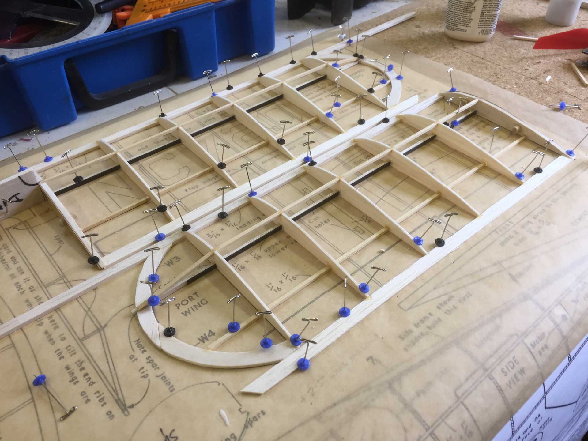
With the fuselage just about complete I've moved on to the flying surfaces.
The wings are very straightforward and as I'd already made the root rib when I built the wing mountings in the fuselage they went together quite quickly
The bottom spar is hard 1/16" balsa with a 0.5 x 3mm carbon strip laminated to it to add some strength , the other spars are 3/32 sq in some bendy hardwood I found in my parts bin Obechi ? I'm sure the carbon will keep them straight. The ribs are 1/16" but I have added an extra one due to the increase in size
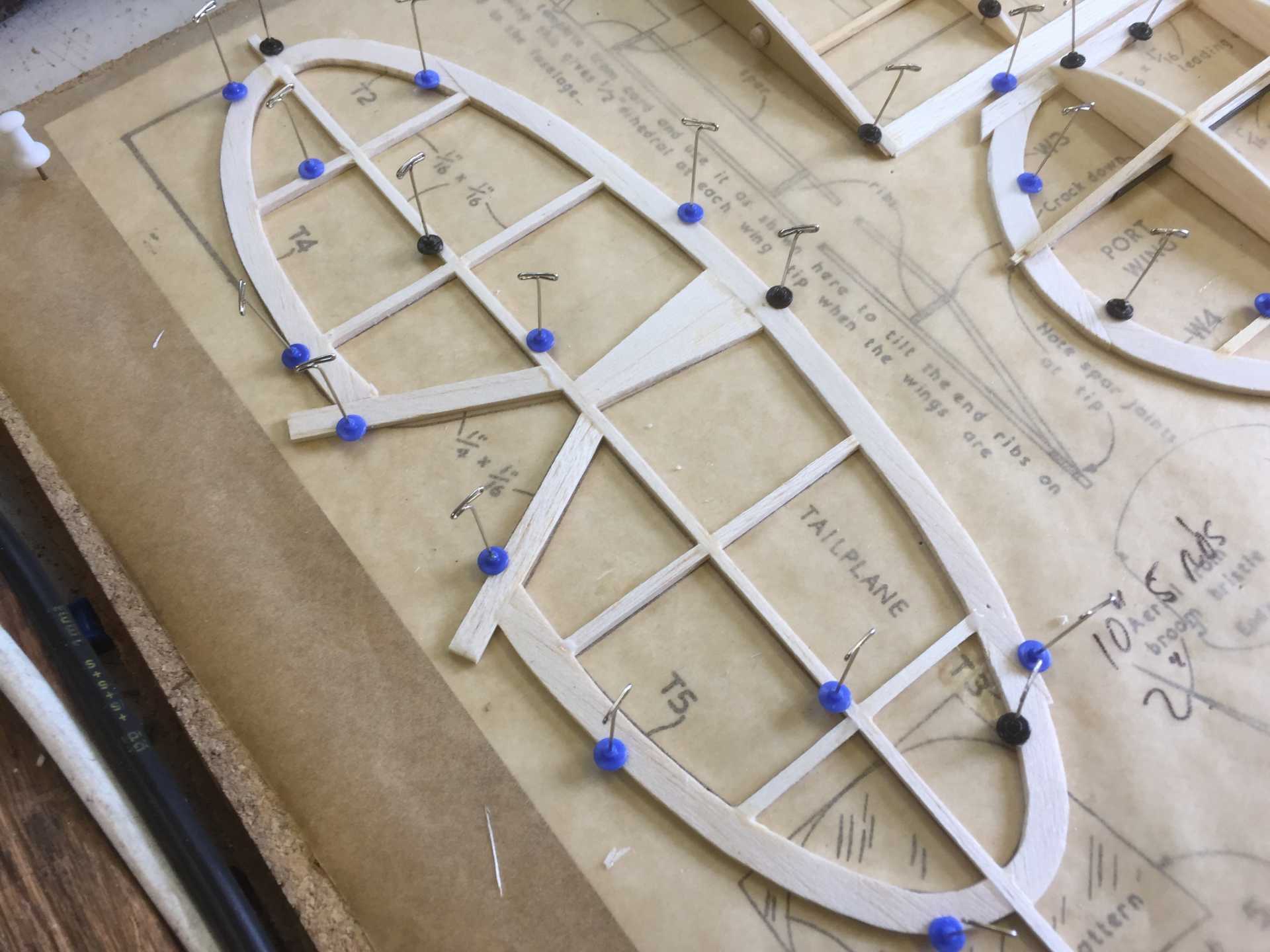
Tail is a very simple flat plate but again I have upped the stock size to 3/32"
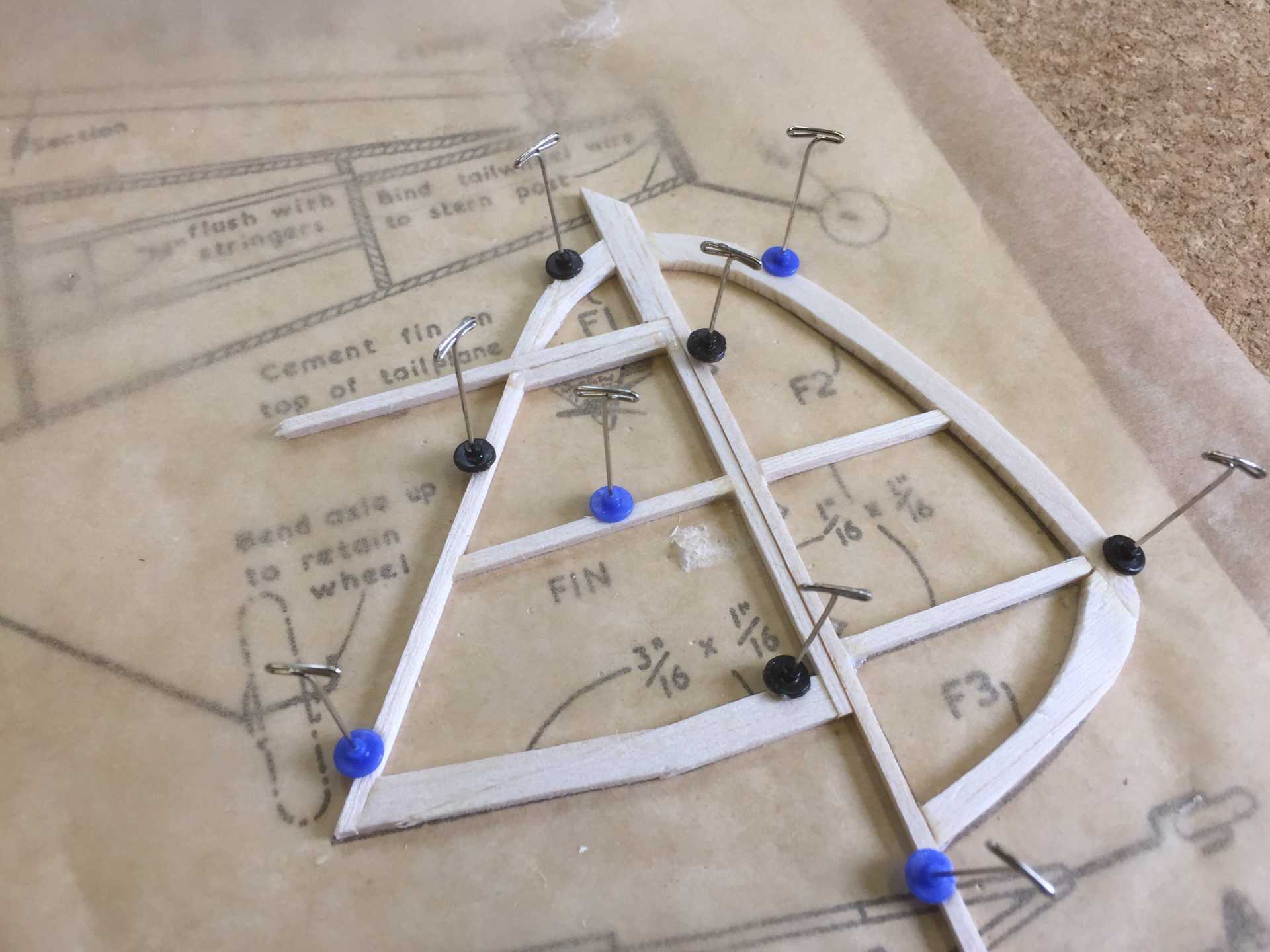
I decided to split the fin and rudder so I could hinge it and have some trim adjustment and I managed to get that built yesterday. It was only when checking some of the reference docs I realised I'd split it vertically and the Piper has a balanced rudder so quick change there...good thing I noticed
Wing mounting uses a hook for a light rubber band to hold the wings to the fuselage and another hook and rubber band system for locating the struts all as per Andy's Thread
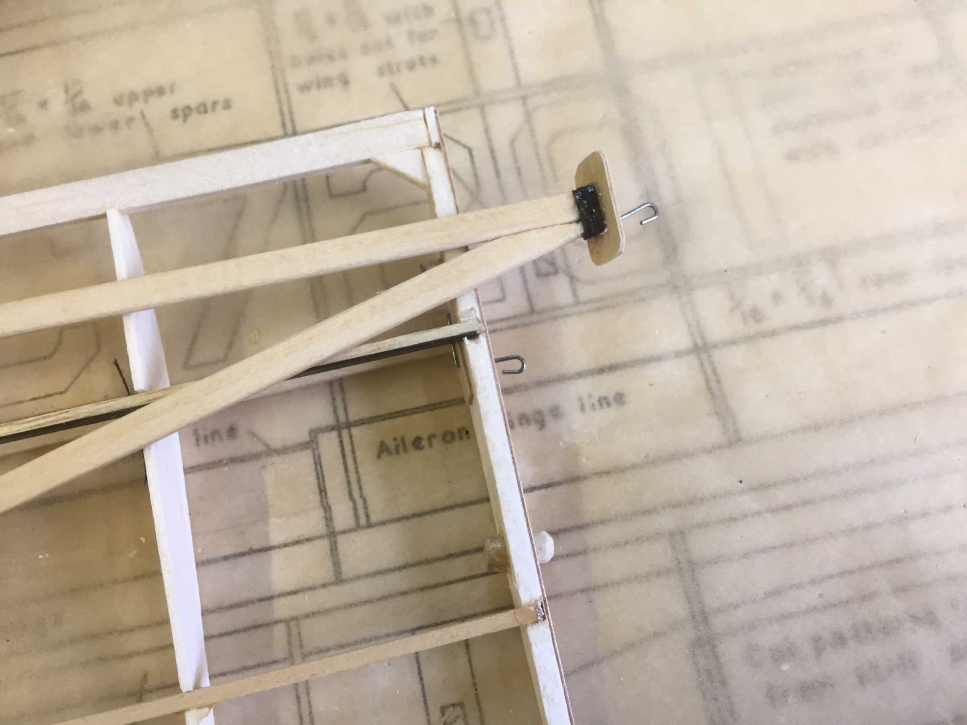
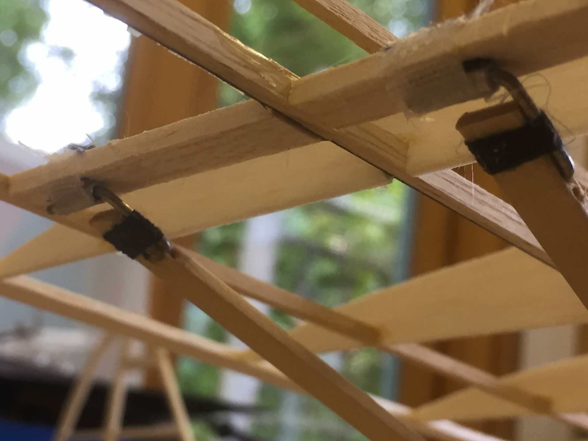
At the wing end of the struts a small piece of Ali tube was cyno'd in the right position and the bound with a layer of Light Glass fibre cloth and then soaked in cyno. The struts have a wire hook which is bound on with thread and again soaked in cyno.
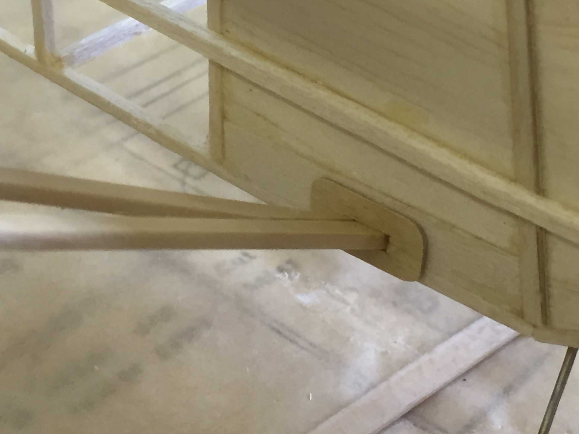
The dihedral is governed by the struts so I made 1/32 ply plate that locates with the fuselage side to give the right amount when pulled tight by the internal rubber band.
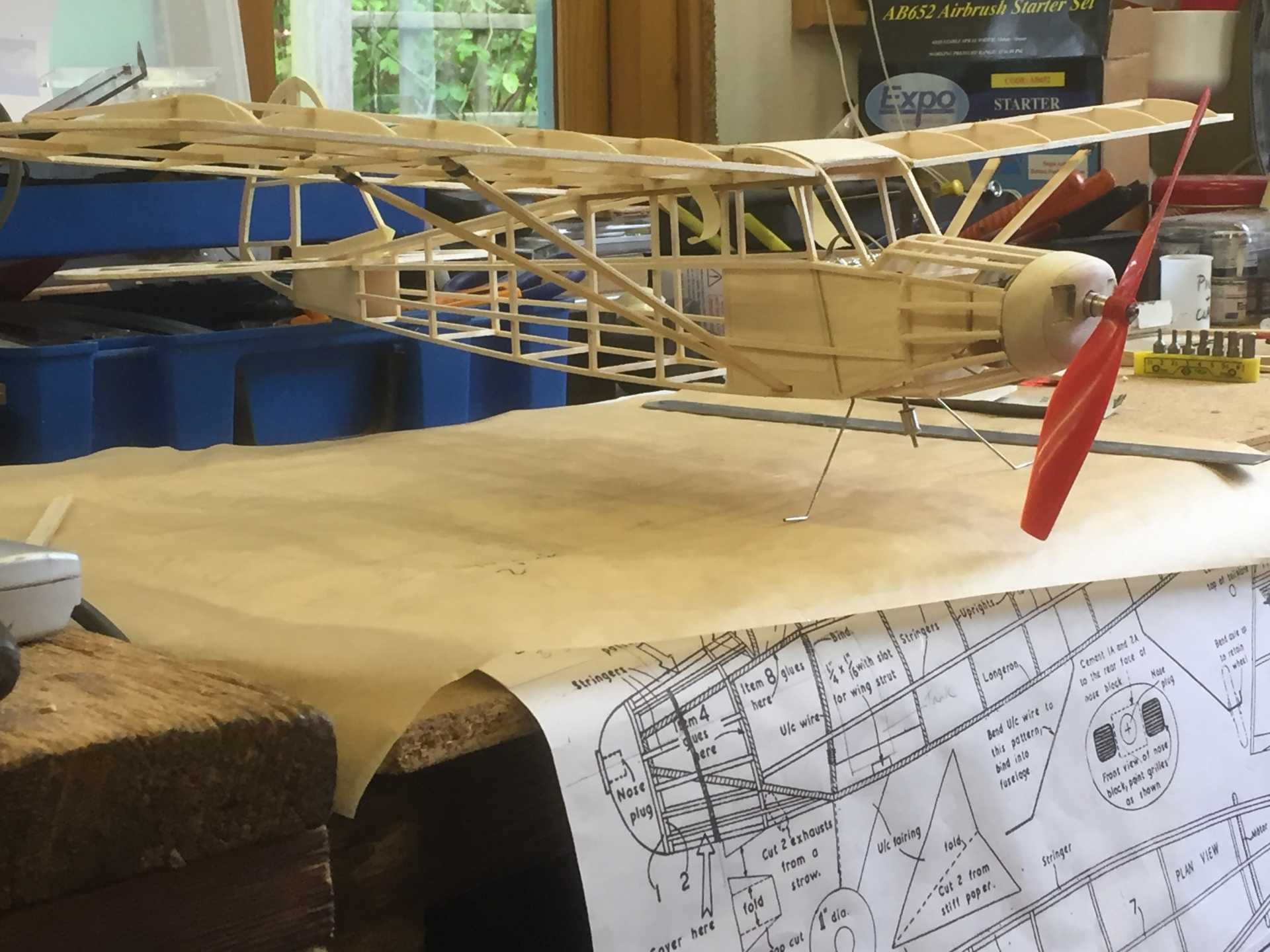
Its all starting to come together now and weight is still around 70g
The wings are very straightforward and as I'd already made the root rib when I built the wing mountings in the fuselage they went together quite quickly
The bottom spar is hard 1/16" balsa with a 0.5 x 3mm carbon strip laminated to it to add some strength , the other spars are 3/32 sq in some bendy hardwood I found in my parts bin Obechi ? I'm sure the carbon will keep them straight. The ribs are 1/16" but I have added an extra one due to the increase in size
Tail is a very simple flat plate but again I have upped the stock size to 3/32"
I decided to split the fin and rudder so I could hinge it and have some trim adjustment and I managed to get that built yesterday. It was only when checking some of the reference docs I realised I'd split it vertically and the Piper has a balanced rudder so quick change there...good thing I noticed
Wing mounting uses a hook for a light rubber band to hold the wings to the fuselage and another hook and rubber band system for locating the struts all as per Andy's Thread
At the wing end of the struts a small piece of Ali tube was cyno'd in the right position and the bound with a layer of Light Glass fibre cloth and then soaked in cyno. The struts have a wire hook which is bound on with thread and again soaked in cyno.
The dihedral is governed by the struts so I made 1/32 ply plate that locates with the fuselage side to give the right amount when pulled tight by the internal rubber band.
Its all starting to come together now and weight is still around 70g
Last edit: 08 May 2017 18:27 by Squirrelnet.
Thanks: Klipkopwildlife, Ex-Member, boz, Firewood, Nigel
Please Log in or Create an account to join the conversation.
- Ex-Member
- Visitor
-
08 May 2017 19:15 #14
by Ex-Member
Replied by Ex-Member on topic Keil Kraft Piper Family Cruiser
Still looking good, Chris.
If it's not too late, you might consider making the elevators separate, too. And if you really want to make life easy, separate ailerons as well.... The latter make trimming for the turn easier and prevents the addition of an unsightly gurney tab. The former is essential for pitch trim.
Either way, I would suggest putting a gusset between the tailplane spar and the centre section. The spar at the centre-section is a weak point, mine broke at the spar several times!
If it's not too late, you might consider making the elevators separate, too. And if you really want to make life easy, separate ailerons as well....
The latter make trimming for the turn easier and prevents the addition of an unsightly gurney tab. The former is essential for pitch trim.Either way, I would suggest putting a gusset between the tailplane spar and the centre section. The spar at the centre-section is a weak point, mine broke at the spar several times!
Please Log in or Create an account to join the conversation.
- Squirrelnet
- Topic Author
- Offline
- Elite Member
-
Less
More
- Posts: 809
- Thank you received: 2067
08 May 2017 19:58 - 08 May 2017 20:17 #15
by Squirrelnet
Replied by Squirrelnet on topic Keil Kraft Piper Family Cruiser
Thanks Andy, no not too late - gussets at the ready Now you say that you can see the rather nasty sharp angle on the tail
My plan is to attach the tail with a light rubber band so I can adjust the tail with shims as is familiar to me in trimming vintage free flight models, once trimmed I can set in the right position. My stupidly crap maths put the wing loading at 25g per dm2 (wing area 13cm x 30 cm 390 cm2 -predicted weight 100g) ... oh hang on - two wings make that 12.5g per dm2. sounds a bit better. If it does go indoors though a gurney flap maybe the way forward
edit - Gurney flap thats motorsport isn't it - Dan Gurney - 1960's road racer, Grand Prix, NASCA and Indy driver. His use of the flap was to increase downforce on the rear wing in the early days of aerodynamics in motor racing I didn't realise it had become a thing in aviation world too.
Now you say that you can see the rather nasty sharp angle on the tailMy plan is to attach the tail with a light rubber band so I can adjust the tail with shims as is familiar to me in trimming vintage free flight models, once trimmed I can set in the right position. My stupidly crap maths put the wing loading at 25g per dm2 (wing area 13cm x 30 cm 390 cm2 -predicted weight 100g) ... oh hang on - two wings
make that 12.5g per dm2. sounds a bit better. If it does go indoors though a gurney flap maybe the way forwardedit - Gurney flap thats motorsport isn't it - Dan Gurney - 1960's road racer, Grand Prix, NASCA and Indy driver. His use of the flap was to increase downforce on the rear wing in the early days of aerodynamics in motor racing I didn't realise it had become a thing in aviation world too.
Last edit: 08 May 2017 20:17 by Squirrelnet.
Thanks: boz, Firewood
Please Log in or Create an account to join the conversation.
Time to create page: 0.348 seconds