
- Posts: 698
- Thank you received: 573
×
Flying models without a radio
Hawker Tomtit - FF Scale Build
- Mike Rolls
-

- Offline
- Elite Member
-

Less
More
16 Aug 2017 20:02 #16
by Mike Rolls
The older I get, the better I was!
Replied by Mike Rolls on topic Hawker Tomtit - FF Scale Build
I've only ever designed two bipes - rigged the upper wing at +1 compared to the lower and both flew fine - one a 24" 2 channel for an Allbon Javelin, the other a 42" psuedo WW1 fighter for 300W electric.
Mike
Mike
The older I get, the better I was!
Thanks: boz
Please Log in or Create an account to join the conversation.
- Nigel
- Offline
- Elite Member
-
Less
More
- Posts: 204
- Thank you received: 405
19 Aug 2017 00:27 - 19 Aug 2017 00:38 #17
by Nigel
Replied by Nigel on topic Hawker Tomtit - FF Scale Build
When I have a bit more time, come October, I will search out the aerodynamic theory (if anyone is bothered) but both the slot effect and the movement rearwards of the centre of lift if the upper wing stalls first, given forward stagger and a greater incidence, are perfectly sound theories - whether they are worth incorporating in models or not is a separate question.
Another tool you could possibly deploy, Chris, might be to experiment with control via differential washout. (Deliberate) wing-warping if you like. The late great free flight exponent, John O'Donnell never left home without it.
By the time you've done all this, you'll be quite expert
Good luck
N
Another tool you could possibly deploy, Chris, might be to experiment with control via differential washout. (Deliberate) wing-warping if you like. The late great free flight exponent, John O'Donnell never left home without it.
By the time you've done all this, you'll be quite expert
Good luck
N
Last edit: 19 Aug 2017 00:38 by Nigel.
Thanks: boz, Firewood
Please Log in or Create an account to join the conversation.
- Squirrelnet
- Topic Author
- Offline
- Elite Member
-
Less
More
- Posts: 809
- Thank you received: 2067
19 Aug 2017 18:11 #18
by Squirrelnet
The plan is fit Ali can hinged ailerons so I can trim the roll too so 'proper' wing warping if you like .
Anyway its already to try again if this wind will drop

Replied by Squirrelnet on topic Hawker Tomtit - FF Scale Build
Another tool you could possibly deploy, Chris, might be to experiment with control via differential washout.
The plan is fit Ali can hinged ailerons so I can trim the roll too so 'proper' wing warping if you like .
Anyway its already to try again if this wind will drop
Thanks: Klipkopwildlife, Quorneng, boz, Firewood
Please Log in or Create an account to join the conversation.
- Squirrelnet
- Topic Author
- Offline
- Elite Member
-
Less
More
- Posts: 809
- Thank you received: 2067
20 Aug 2017 18:04 - 20 Aug 2017 18:09 #19
by Squirrelnet
Replied by Squirrelnet on topic Hawker Tomtit - FF Scale Build
Well the wind has dropped ..but now its started raining !
I spent most of afternoon drawing out the fuselage anyway, so hopeful I can get the Tomtit-enezer to work. The thrust angle can always be changed before I commit to building it, as its not too much work to re draw that bit - though 2 deg down looks good at the moment. I've managed to resolve most of the fuselage out into something I can build with a box section being the heart of it all. Not sure wether to go for hard 1/8" sq balsa or medium 3/32" , I'm thinking medium 3/32" at the moment. Any thoughts ??
The top decking will be 1/32 sheet for the bits that were ply covered on the original with 1/8" x 1/32" hard balsa stringers or perhaps 1/8" x 1/16" or perhaps thin basswood again not sure . The strip would be on edge to give sharp line to the covering.
The load bearing formers for the wing mounts, U/C and Cabane struts will be 1/8" ply and the lower wing mount built as a strong structure as this will be main load bearing bit for the wings. The plan is to use 3mm carbon rods in Ali tube for the wing mounts which will set the dihedral with the top located on half round dowels and fixed with an internal rubber band with working fishing line rigging using small rubbers bands at the top end. Its the method I used on the DH60, though I chickened out with the top wing and used wire dowels instead but not sure it really needs them

I bought a suitable pilot for the model from SAMS , but he keeps nearly getting damaged as he looks like a lump of foam ... which he is... so I thought I'd paint him so he's easy to spot in the workshop and perhaps pack him away until he's needed.
He seems suitably intent on the job, though it looks like he's had to resort to dutch courage already. Free flight pilots are a hardy bunch I seem to remember Andy has one who's head is glued to the main spar !!!

I spent most of afternoon drawing out the fuselage anyway, so hopeful I can get the Tomtit-enezer to work. The thrust angle can always be changed before I commit to building it, as its not too much work to re draw that bit - though 2 deg down looks good at the moment. I've managed to resolve most of the fuselage out into something I can build with a box section being the heart of it all. Not sure wether to go for hard 1/8" sq balsa or medium 3/32" , I'm thinking medium 3/32" at the moment. Any thoughts ??
The top decking will be 1/32 sheet for the bits that were ply covered on the original with 1/8" x 1/32" hard balsa stringers or perhaps 1/8" x 1/16" or perhaps thin basswood again not sure . The strip would be on edge to give sharp line to the covering.
The load bearing formers for the wing mounts, U/C and Cabane struts will be 1/8" ply and the lower wing mount built as a strong structure as this will be main load bearing bit for the wings. The plan is to use 3mm carbon rods in Ali tube for the wing mounts which will set the dihedral with the top located on half round dowels and fixed with an internal rubber band with working fishing line rigging using small rubbers bands at the top end. Its the method I used on the DH60, though I chickened out with the top wing and used wire dowels instead but not sure it really needs them
I bought a suitable pilot for the model from SAMS , but he keeps nearly getting damaged as he looks like a lump of foam ... which he is... so I thought I'd paint him so he's easy to spot in the workshop and perhaps pack him away until he's needed.
He seems suitably intent on the job, though it looks like he's had to resort to dutch courage already. Free flight pilots are a hardy bunch I seem to remember Andy has one who's head is glued to the main spar !!!
Last edit: 20 Aug 2017 18:09 by Squirrelnet.
Thanks: Klipkopwildlife, boz, Firewood, Crashrr
Please Log in or Create an account to join the conversation.
- Ex-Member
- Visitor
-

20 Aug 2017 18:10 #20
by Ex-Member
Replied by Ex-Member on topic Hawker Tomtit - FF Scale Build
I would go for 1/8 sq spruce for the basic fuselage and wire dowels to hold on the wing. Carbon is stronger and lighter than wire, but it doesn't bend and won't 'give' in a crash. Strength with lightness comes from flexibility in FF scale models. 
Please Log in or Create an account to join the conversation.
- Squirrelnet
- Topic Author
- Offline
- Elite Member
-
Less
More
- Posts: 809
- Thank you received: 2067
20 Aug 2017 18:22 - 20 Aug 2017 18:35 #21
by Squirrelnet
Replied by Squirrelnet on topic Hawker Tomtit - FF Scale Build
Thanks Andy I had not thought of Spruce for the fuselage.
I have broken a couple of sets of 3mm Carbon dowels with the DH60 during trimming it. They split with the stress but in doing so seem to have bit of give.
Not sure the though as the bottom line is can I fit them in the wing section with the dihedral as they need a straight run , wires can be bent to shape
I have broken a couple of sets of 3mm Carbon dowels with the DH60 during trimming it. They split with the stress but in doing so seem to have bit of give.
Not sure the though as the bottom line is can I fit them in the wing section with the dihedral as they need a straight run , wires can be bent to shape
Last edit: 20 Aug 2017 18:35 by Squirrelnet.
Thanks: boz
Please Log in or Create an account to join the conversation.
- one tenor
-

- Offline
- Forum Veteran
-

- johnpcalex@gmail.com
21 Aug 2017 00:08 #22
by one tenor
Anything will fly given enough power
Replied by one tenor on topic Hawker Tomtit - FF Scale Build
Get thicker section spruce and cut to suit the dihedral angle.Use a scroll saw or bandsaw if you have one.Otherwise it's a handsaw. Fret or coping or just possibly a jig-saw with a fine blade and clamps to hold the wood firmly ![[badass]](/media/kunena/emoticons/bad_boys_20.gif "[badass]") Good luck
Good luck
Good luck Anything will fly given enough power
Thanks: boz, Squirrelnet
Please Log in or Create an account to join the conversation.
- Squirrelnet
- Topic Author
- Offline
- Elite Member
-
Less
More
- Posts: 809
- Thank you received: 2067
31 Aug 2017 18:37 - 31 Aug 2017 18:51 #23
by Squirrelnet
Replied by Squirrelnet on topic Hawker Tomtit - FF Scale Build
I managed a bit more with the Tomtit today, though it was all scribbling rather than building .
That great weather at the Nats last weekend allowed me to trim out the small telco powered Tomtit-enezer. It now happily flies in left circuit thanks largely due to Andy's helpful advice. I added some positive left aileron and found it needed less tail packing to fly , not sure why that happened but 2 deg down thrust is good which is handy now I've drawn it on my plan
Side thrust I'm less sure about as the telco version is using 5.5 deg of right thrust but it's using a prop which is 1/3 the size of the wingspan so the torque could be very large. My diesel powered version will have a prop more like 1/4 of the wingspan so torque will be reduced ????? I think ??? I was thinking if that's the case to copy the side thrust from the Veron plan which is two deg but I'll make it easy to change by mounting the engine on a metal plate. I was thinking of angling the engine bearers to some extent to help keep the thrust line central.
Hoping to get the basic fuselage box with U/C built in the next few days

That great weather at the Nats last weekend allowed me to trim out the small telco powered Tomtit-enezer. It now happily flies in left circuit thanks largely due to Andy's helpful advice. I added some positive left aileron and found it needed less tail packing to fly , not sure why that happened but 2 deg down thrust is good which is handy now I've drawn it on my plan
Side thrust I'm less sure about as the telco version is using 5.5 deg of right thrust but it's using a prop which is 1/3 the size of the wingspan so the torque could be very large. My diesel powered version will have a prop more like 1/4 of the wingspan so torque will be reduced ????? I think ??? I was thinking if that's the case to copy the side thrust from the Veron plan which is two deg but I'll make it easy to change by mounting the engine on a metal plate. I was thinking of angling the engine bearers to some extent to help keep the thrust line central.
Hoping to get the basic fuselage box with U/C built in the next few days
Last edit: 31 Aug 2017 18:51 by Squirrelnet.
Thanks: Klipkopwildlife, Quorneng, Ex-Member, Ralpharr2001, one tenor, boz, Firewood, Mike Rolls
Please Log in or Create an account to join the conversation.
- Squirrelnet
- Topic Author
- Offline
- Elite Member
-
Less
More
- Posts: 809
- Thank you received: 2067
05 Sep 2017 19:11 - 05 Sep 2017 19:13 #24
by Squirrelnet
Replied by Squirrelnet on topic Hawker Tomtit - FF Scale Build
The Flying Aces saw some more action for the Tomtit-enezer, it's turned out to be fun little model in itself and it seems to be fairly indistructable ( It'll break next time out now  ) It has also had the benefit making me want to get on with the bigger one so with a bit more drawing time I've just about sorted the plan view of the fuselage.

Actually looking at the drawing I think I will shift the engine bearers more to left to give me some wriggle room in case I need more side thrust and need to move the engine further left to keep the prop central
Although I have not fully drawn the model yet I have at least resolved how to do fuselage enough to begin the basic box section that forms the structural heart of the model.
The wings , tail and fin and rudder will be more straight forward once the bit that joins them all together is sorted.
The box section is combination of 1/8" spruce and hard Balsa and has a 3/32" with 1/32 ply doubler around the lower wing mount. Undercarriage and Cabane formers will 1/8" birch ply

I now have two sides

Next I'll bend up the under carriage and form the rear fuselage into a box section
) It has also had the benefit making me want to get on with the bigger one so with a bit more drawing time I've just about sorted the plan view of the fuselage.
Actually looking at the drawing I think I will shift the engine bearers more to left to give me some wriggle room in case I need more side thrust and need to move the engine further left to keep the prop central
Although I have not fully drawn the model yet I have at least resolved how to do fuselage enough to begin the basic box section that forms the structural heart of the model.
The wings , tail and fin and rudder will be more straight forward once the bit that joins them all together is sorted.
The box section is combination of 1/8" spruce and hard Balsa and has a 3/32" with 1/32 ply doubler around the lower wing mount. Undercarriage and Cabane formers will 1/8" birch ply
I now have two sides
Next I'll bend up the under carriage and form the rear fuselage into a box section
Last edit: 05 Sep 2017 19:13 by Squirrelnet.
Thanks: Klipkopwildlife, Quorneng, Ex-Member, boz, Firewood
Please Log in or Create an account to join the conversation.
- Ex-Member
- Visitor
-
05 Sep 2017 19:38 #25
by Ex-Member
Replied by Ex-Member on topic Hawker Tomtit - FF Scale Build
lovely looking build sir.
going to be a smasher i think.
Tony B
going to be a smasher i think.
Tony B
Please Log in or Create an account to join the conversation.
- Squirrelnet
- Topic Author
- Offline
- Elite Member
-
Less
More
- Posts: 809
- Thank you received: 2067
06 Sep 2017 18:21 - 06 Sep 2017 18:39 #26
by Squirrelnet
Replied by Squirrelnet on topic Hawker Tomtit - FF Scale Build
It's starting to look like something a bit more than just an idea as the basic frame comes together.

The more time spent getting it square now will hopefully make life easier further down the road so with that in mind it took me all afternoon to bend up the undercarriage and work out the front fixing which will be buried inside the nose. The rear legs hinge in brass tube and the front legs will be sprung with a rubber band.

The scrap ply between the engine bearers and the front UC legs is just so it stands up. A couple of L shaped boxes will be built to locate the leg
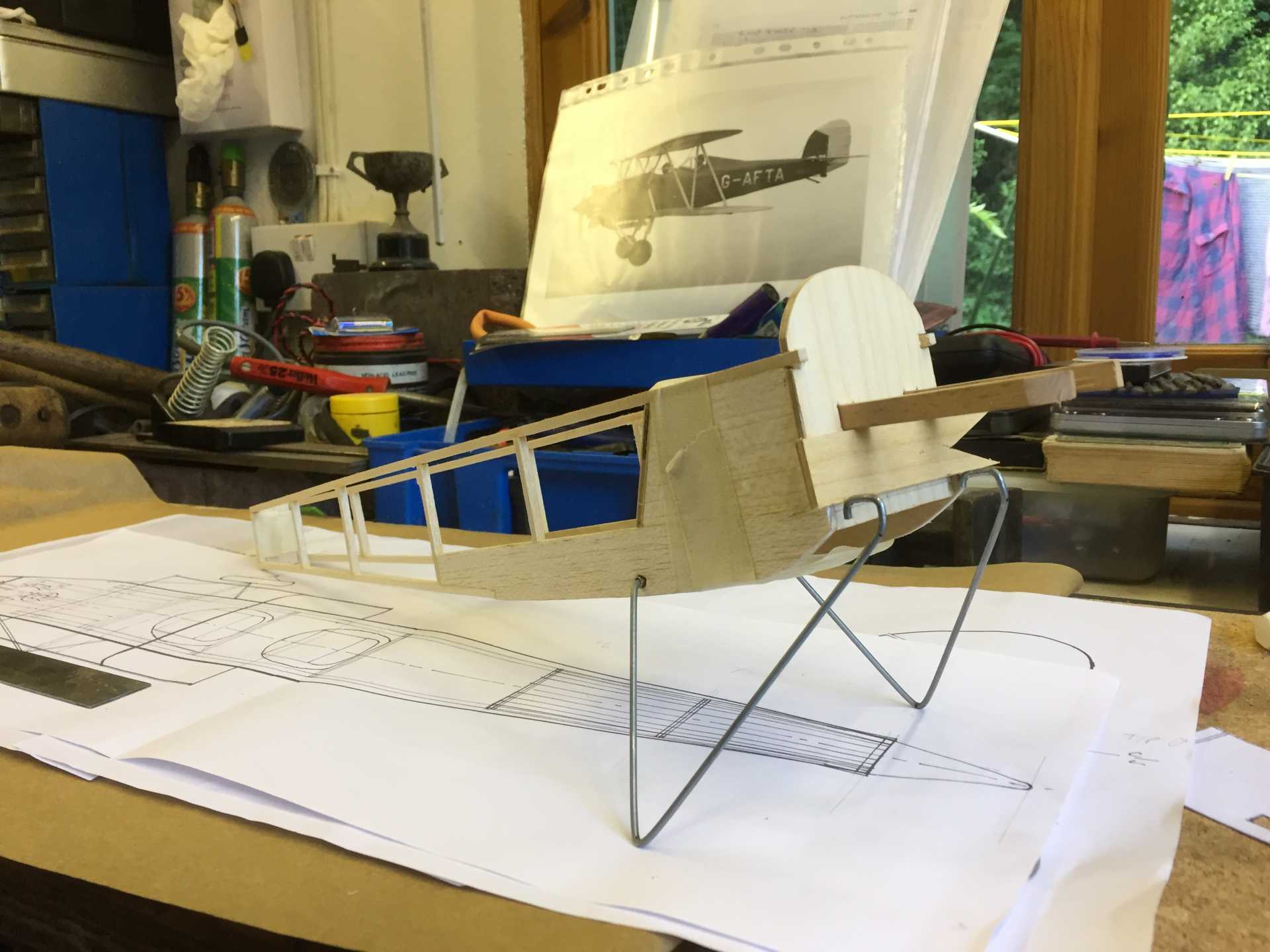
The more time spent getting it square now will hopefully make life easier further down the road so with that in mind it took me all afternoon to bend up the undercarriage and work out the front fixing which will be buried inside the nose. The rear legs hinge in brass tube and the front legs will be sprung with a rubber band.
The scrap ply between the engine bearers and the front UC legs is just so it stands up. A couple of L shaped boxes will be built to locate the leg
Last edit: 06 Sep 2017 18:39 by Squirrelnet.
Thanks: Klipkopwildlife, Quorneng, Ex-Member, Ralpharr2001, boz, Firewood, Paul H
Please Log in or Create an account to join the conversation.
- Squirrelnet
- Topic Author
- Offline
- Elite Member
-
Less
More
- Posts: 809
- Thank you received: 2067
07 Sep 2017 18:48 - 07 Sep 2017 19:02 #27
by Squirrelnet
Replied by Squirrelnet on topic Hawker Tomtit - FF Scale Build
I now have a basic box section for the fuselage.


The priority though is still to sort out the placement of the undercarriage and wing mounts before going much further with actual shape of the fuselage. Cockpit detail will be added too before I add any stringers and side formers.
The main job of today was re-thinking the Undercarriage . I have decided ( after prompting by those more knowledgeable - thanks Andy ) to adopt the full-size arrangement of having the front legs hinge and the rear legs able to compress. This should give different main leg lengths for static and flying as per full-size . To this end I need to make a compressible rear leg that can fit inside the dummy Oleo leg.
A rummage in parts box came up with some brass tube to fit the 14swg I have for the legs and some larger diameter brass tube, a bit of brass sheet and my note book pen gave me a spring .
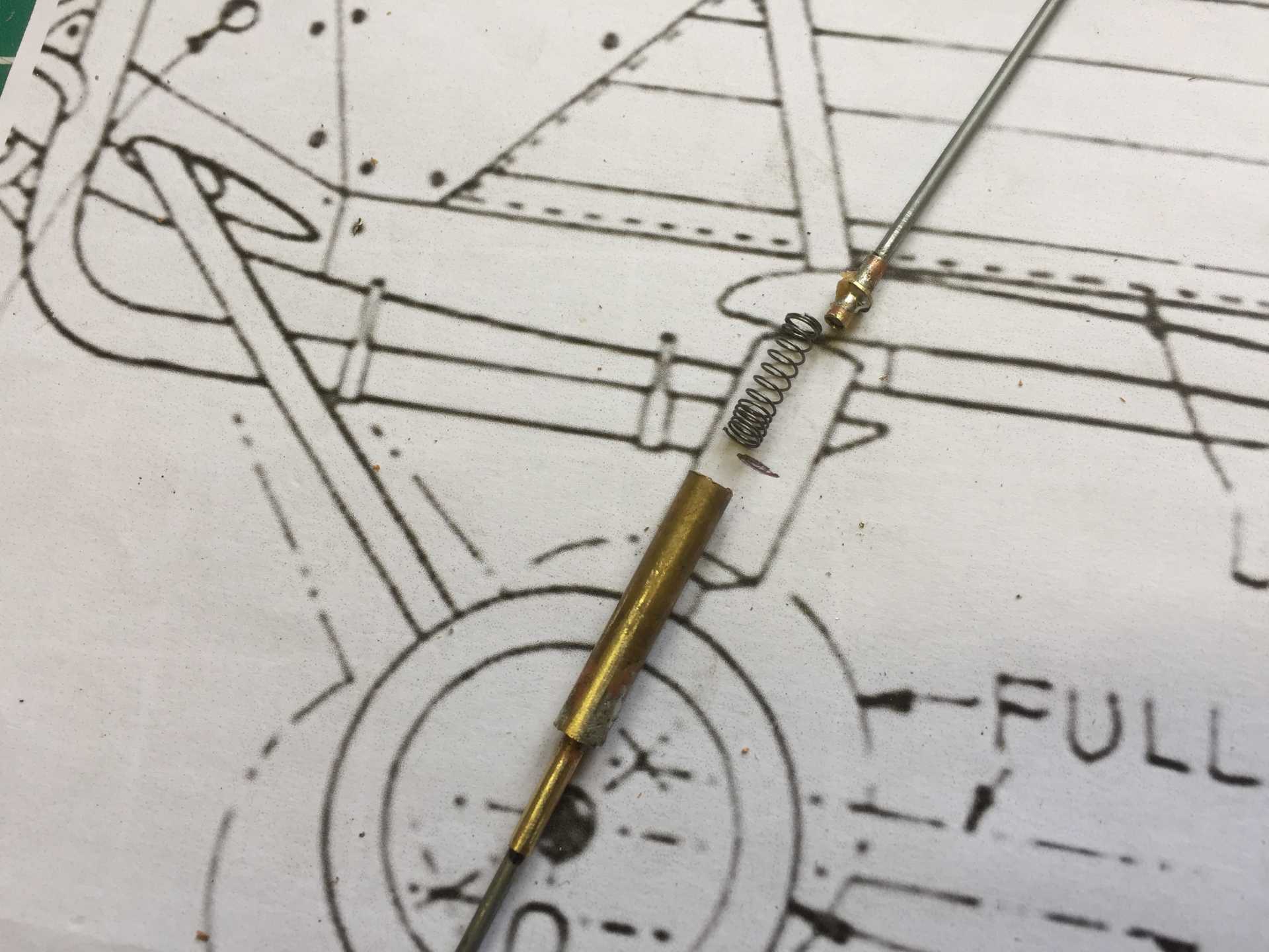
The idea is that the 14swg piano wire and brass tube are the sliding component of the unit and about 3/4" long so there's plenty of bearing surface. On the end of the wire is soldered a brass washer ( not visible in the photo ) which provides the bottom stop so it can't come out of the tube .Around this fits the larger diameter tube which is soldered to the inner tube with a brass washer. The spring is pushed by the wire bottom stop washer which forms a plunger and compresses the spring against the top mont for the unit made from another brass washer and smaller diameter tube . The gap between the top and bottom bits of 14swg tube is 1/2" so it gives 1/2" of movement.... and if you can follow that then you are doing better than me
The whole thing is soldered together so hopefully will with stand the FF landing loads
The biro spring needs too much to compress it at about 10 ozs to reach full travel, as the model will hopefully be around 10 ozs it won't sit correctly as there will be 2 legs and some weight is on the tail so I chopped the spring in half . This gives more free travel but the compression bit is still a bit tough and at 4ozs per leg ( its a guess) it won't fully compress to the static length.
I'm not sure I even need a spring, maybe just gravity is enough with it locking up in a landing and acting like a fixed undercarriage . Or maybe I could wind a small lighter spring which would at least give a bit off cushioning in a landing but where do you get fine spring steel ??
In the model the unit will be concealed inside a dummy Oleo

The priority though is still to sort out the placement of the undercarriage and wing mounts before going much further with actual shape of the fuselage. Cockpit detail will be added too before I add any stringers and side formers.
The main job of today was re-thinking the Undercarriage . I have decided ( after prompting by those more knowledgeable - thanks Andy
) to adopt the full-size arrangement of having the front legs hinge and the rear legs able to compress. This should give different main leg lengths for static and flying as per full-size . To this end I need to make a compressible rear leg that can fit inside the dummy Oleo leg.A rummage in parts box came up with some brass tube to fit the 14swg I have for the legs and some larger diameter brass tube, a bit of brass sheet and my note book pen gave me a spring .
The idea is that the 14swg piano wire and brass tube are the sliding component of the unit and about 3/4" long so there's plenty of bearing surface. On the end of the wire is soldered a brass washer ( not visible in the photo ) which provides the bottom stop so it can't come out of the tube .Around this fits the larger diameter tube which is soldered to the inner tube with a brass washer. The spring is pushed by the wire bottom stop washer which forms a plunger and compresses the spring against the top mont for the unit made from another brass washer and smaller diameter tube . The gap between the top and bottom bits of 14swg tube is 1/2" so it gives 1/2" of movement.... and if you can follow that then you are doing better than me
The whole thing is soldered together so hopefully will with stand the FF landing loads
The biro spring needs too much to compress it at about 10 ozs to reach full travel, as the model will hopefully be around 10 ozs it won't sit correctly as there will be 2 legs and some weight is on the tail so I chopped the spring in half . This gives more free travel but the compression bit is still a bit tough and at 4ozs per leg ( its a guess) it won't fully compress to the static length.
I'm not sure I even need a spring, maybe just gravity is enough with it locking up in a landing and acting like a fixed undercarriage . Or maybe I could wind a small lighter spring which would at least give a bit off cushioning in a landing but where do you get fine spring steel ??
In the model the unit will be concealed inside a dummy Oleo
Last edit: 07 Sep 2017 19:02 by Squirrelnet.
Thanks: Klipkopwildlife, Quorneng, old fart, Ex-Member, boz, Firewood, Mike Rolls
Please Log in or Create an account to join the conversation.
- Quorneng
-

- Offline
- Forum Master
-

Less
More
- Posts: 10058
- Thank you received: 19043
07 Sep 2017 19:15 #28
by Quorneng
Replied by Quorneng on topic Hawker Tomtit - FF Scale Build
Nicely done!
Is that spring strong enough not to 'bottom out' in any sort of firm landing?
Once there is no more travel the undercarriage behaves as if it is 'rigid' and is thus more likely to rip out.
This was one of the advantages of a rubber (or air) in compression type as it has a rising 'spring rate' - it gets progressively stiffer as it compresses so never truly 'bottoms out' whereas a coil spring has a constant rate - each additional unit of load compresses the spring by the same amount until the coils touch.
FF (or even RC) planes tend to need a 'long stroke' undercarriage to avoid damage.
Is that spring strong enough not to 'bottom out' in any sort of firm landing?
Once there is no more travel the undercarriage behaves as if it is 'rigid' and is thus more likely to rip out.
This was one of the advantages of a rubber (or air) in compression type as it has a rising 'spring rate' - it gets progressively stiffer as it compresses so never truly 'bottoms out' whereas a coil spring has a constant rate - each additional unit of load compresses the spring by the same amount until the coils touch.
FF (or even RC) planes tend to need a 'long stroke' undercarriage to avoid damage.
Thanks: boz, Squirrelnet
Please Log in or Create an account to join the conversation.
- Squirrelnet
- Topic Author
- Offline
- Elite Member
-
Less
More
- Posts: 809
- Thank you received: 2067
07 Sep 2017 19:36 #29
by Squirrelnet
Replied by Squirrelnet on topic Hawker Tomtit - FF Scale Build
Good thoughts Q .
My idea is that it can bottom out as with a model this size - 28" span and (hopefully) upto 10 ozs - a fixed undercarriage, with adequate strengthening around the mounts will be fine. A softer approach to the lock up to solid would be helpful though in any engineering book . I did think about some kind of nylon or similar buffer but with the small scale, the ID of the outer brass tube is just 3/16" I thought it would just get chewed up pretty quickly and I'm not keen on making these units 'servicable'
My idea is that it can bottom out as with a model this size - 28" span and (hopefully) upto 10 ozs - a fixed undercarriage, with adequate strengthening around the mounts will be fine. A softer approach to the lock up to solid would be helpful though in any engineering book . I did think about some kind of nylon or similar buffer but with the small scale, the ID of the outer brass tube is just 3/16" I thought it would just get chewed up pretty quickly and I'm not keen on making these units 'servicable'
Thanks: boz
Please Log in or Create an account to join the conversation.
- one tenor
-
- Offline
- Forum Veteran
-
- johnpcalex@gmail.com
07 Sep 2017 20:33 - 07 Sep 2017 20:55 #30
by one tenor
Anything will fly given enough power
Replied by one tenor on topic Hawker Tomtit - FF Scale Build
You might find suitable springs amongst this lot .
www.leespring.com/uk_index.asp? CountryCode=011&utm_source=UK%20Google%20AdWords%20Campaigns&utm_medium=Google%20AdWords%20Search%20Network&utm_campaign=UK%20Products
Additional sources are jewellers,watch/clock makers or your local engineering suppliers. Also Model fixings on line. Somewhere where you can see for yourself what you need is probably best .Nice work by the way.
P.S. Also look at model steam engine supplies .
www.leespring.com/uk_index.asp? CountryCode=011&utm_source=UK%20Google%20AdWords%20Campaigns&utm_medium=Google%20AdWords%20Search%20Network&utm_campaign=UK%20Products
Additional sources are jewellers,watch/clock makers or your local engineering suppliers. Also Model fixings on line. Somewhere where you can see for yourself what you need is probably best .Nice work by the way.
P.S. Also look at model steam engine supplies .
Anything will fly given enough power
Last edit: 07 Sep 2017 20:55 by one tenor. Reason: additional script
Thanks: boz, Squirrelnet
Please Log in or Create an account to join the conversation.
Time to create page: 0.397 seconds