
- Posts: 10058
- Thank you received: 19043
Depron Heinkel HE162
- Quorneng
-
 Topic Author
- Offline
- Forum Master
-

Less
More
16 Feb 2021 15:12 - 16 Feb 2021 15:15 #76
by Quorneng
Replied by Quorneng on topic Depron Heinkel HE162
3D printing to the rescue. 
Small and light bolt 'pads' and 'nuts' specifically shaped to be glued into the wing and fuselage structure.

Two bolts close to the wing leading edge.
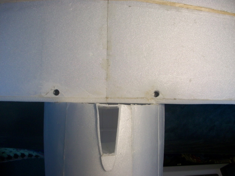
One at the rear on the wing centre line.
The front 'nut' under the wing mount and also glued to the fuselage skin..

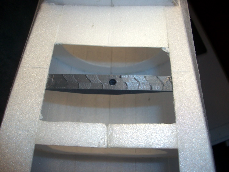
The rear centre line bolt needed a 'bridge' nut to transfer the forces to the skin on either side.
Finally a first stress test. At close to the all up flying weight and supported by its wing tips.

As the nacelle sits on the fuselage all the weight is being transferred to the wing by just the three wing bolts.
Small and light bolt 'pads' and 'nuts' specifically shaped to be glued into the wing and fuselage structure.
Two bolts close to the wing leading edge.
One at the rear on the wing centre line.
The front 'nut' under the wing mount and also glued to the fuselage skin..
The rear centre line bolt needed a 'bridge' nut to transfer the forces to the skin on either side.
Finally a first stress test. At close to the all up flying weight and supported by its wing tips.
As the nacelle sits on the fuselage all the weight is being transferred to the wing by just the three wing bolts.
Attachments:
Last edit: 16 Feb 2021 15:15 by Quorneng.
Thanks: Klipkopwildlife, Ralpharr2001, crash happy, supertigrefan
Please Log in or Create an account to join the conversation.
- paul d
-
- Offline
- Forum Veteran
-

Less
More
- Posts: 2074
- Thank you received: 2292
16 Feb 2021 15:37 - 16 Feb 2021 15:44 #77
by paul d
balsa is best.
Replied by paul d on topic Depron Heinkel HE162
Nice job! saw a book in WH Smith's today about the design, development and operation of the 162, £10.95 flicking through it seems there where plans for a twin engined version.

balsa is best.
Attachments:
Last edit: 16 Feb 2021 15:44 by paul d.
Thanks: Klipkopwildlife, crash happy
Please Log in or Create an account to join the conversation.
- Quorneng
-
Topic Author
- Offline
- Forum Master
-
Less
More
- Posts: 10058
- Thank you received: 19043
16 Feb 2021 18:16 #78
by Quorneng
Replied by Quorneng on topic Depron Heinkel HE162
Paul
That looks an interesting book.
From what I understand the BMW 003 jet was considered a weak design with little room for improvement in terms of both reliability and thrust but it was the only jet engine available for the HE 162. The rather more powerful and cheaper to produce Jumo 004 was reserved for the ME 262 and Arado Blitz.
I believe what is shown on that cover is powered by a pair of pulse jets similar to those used on the V-1. It was not surprising that Heinkel considered this as the pulse jets were easier and a lot cheaper to produce. The real drawback, apart from horrendous vibration, was a very high fuel consumption that was even worse than the early jet engines and a life between overhaul measured in minutes rather than the 20-30 hours of the BMW 003.
I doubt such a configuration would have ever been realistic given the Luftwaffe's poor field maintenance facilities and a chronic fuel shortage?
That looks an interesting book.
From what I understand the BMW 003 jet was considered a weak design with little room for improvement in terms of both reliability and thrust but it was the only jet engine available for the HE 162. The rather more powerful and cheaper to produce Jumo 004 was reserved for the ME 262 and Arado Blitz.
I believe what is shown on that cover is powered by a pair of pulse jets similar to those used on the V-1. It was not surprising that Heinkel considered this as the pulse jets were easier and a lot cheaper to produce. The real drawback, apart from horrendous vibration, was a very high fuel consumption that was even worse than the early jet engines and a life between overhaul measured in minutes rather than the 20-30 hours of the BMW 003.
I doubt such a configuration would have ever been realistic given the Luftwaffe's poor field maintenance facilities and a chronic fuel shortage?
Thanks: Klipkopwildlife, crash happy
Please Log in or Create an account to join the conversation.
- paul d
-
- Offline
- Forum Veteran
-
Less
More
- Posts: 2074
- Thank you received: 2292
16 Feb 2021 20:31 #79
by paul d
balsa is best.
Replied by paul d on topic Depron Heinkel HE162
Well spotted! I never took much notice tbh.....I've just been offered a pulse jet...I'm sorely tempted!
balsa is best.
Thanks: Klipkopwildlife
Please Log in or Create an account to join the conversation.
- Quorneng
-
Topic Author
- Offline
- Forum Master
-
Less
More
- Posts: 10058
- Thank you received: 19043
16 Feb 2021 22:52 #80
by Quorneng
Replied by Quorneng on topic Depron Heinkel HE162
Interesting but could you actually ever use it?
Thanks: Klipkopwildlife
Please Log in or Create an account to join the conversation.
- Quorneng
-
Topic Author
- Offline
- Forum Master
-
Less
More
- Posts: 10058
- Thank you received: 19043
17 Feb 2021 14:01 #81
by Quorneng
Replied by Quorneng on topic Depron Heinkel HE162
Been wracking my brains trying to solve a conflicting problem.
The three point wing fixing is simple, light and quite adequate but for other simple and light weight reason I really need to permanently build the motor nacelle on top of the fuselage. This would however make it impossible to access rear centre wing bolt.
I was just about to start to cut open the wing to insert additional reinforcement to enable two widely spaced rear bolts but it occurred to me does the rear bolt have to be perpendicular?
A bit of work with an adjustable set square indicated that if the bolt was angle at 55 degrees it just clear the nacelle although it might need a long screwdriver.
Creating holes in objects at specific angles other than 0 & 90 degrees is a bit of a pain, particularly in FreeCad so that was the task this morning,
5 hours later we have.

The angle of the bolt does indeed clear the nacelle.
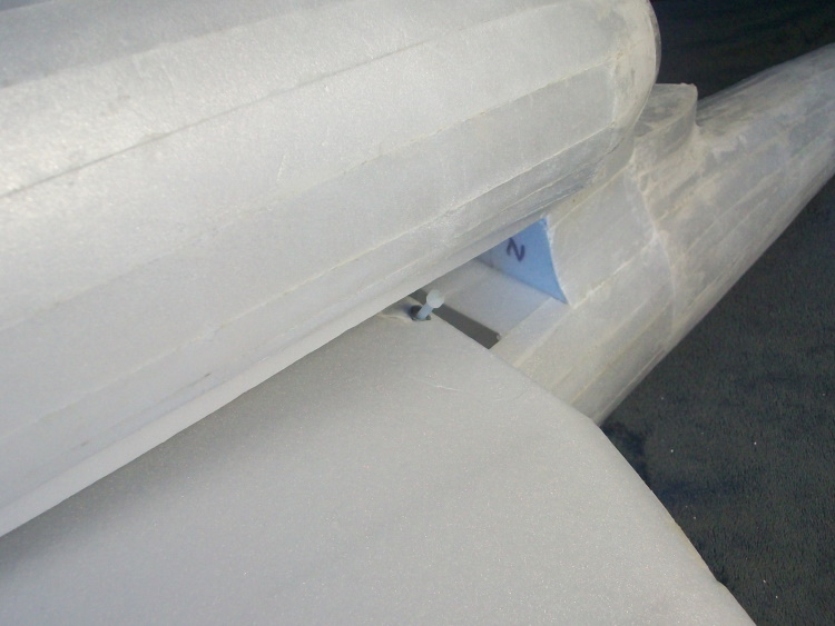
When the fuselage is built up on the wing to meet the nacelle the bolt will be accesses via a long tube.
Once the bolts are removed the wing will be able to slid out sideways. As the wing is removed it will leave a large gap between the nacelle and the fuselage. This will be vital to give clearance for the down turned wing tip - I hope.
I think this means the end of the construction 'trial and error', or now it just needs doing.
The three point wing fixing is simple, light and quite adequate but for other simple and light weight reason I really need to permanently build the motor nacelle on top of the fuselage. This would however make it impossible to access rear centre wing bolt.
I was just about to start to cut open the wing to insert additional reinforcement to enable two widely spaced rear bolts but it occurred to me does the rear bolt have to be perpendicular?
A bit of work with an adjustable set square indicated that if the bolt was angle at 55 degrees it just clear the nacelle although it might need a long screwdriver.
Creating holes in objects at specific angles other than 0 & 90 degrees is a bit of a pain, particularly in FreeCad so that was the task this morning,
5 hours later we have.
The angle of the bolt does indeed clear the nacelle.
When the fuselage is built up on the wing to meet the nacelle the bolt will be accesses via a long tube.
Once the bolts are removed the wing will be able to slid out sideways. As the wing is removed it will leave a large gap between the nacelle and the fuselage. This will be vital to give clearance for the down turned wing tip - I hope.
I think this means the end of the construction 'trial and error', or now it just needs doing.
Attachments:
Thanks: Eric, Klipkopwildlife, crash happy
Please Log in or Create an account to join the conversation.
- paul d
-
- Offline
- Forum Veteran
-
Less
More
- Posts: 2074
- Thank you received: 2292
17 Feb 2021 14:10 #82
by paul d
Thanks: Klipkopwildlife
Please Log in or Create an account to join the conversation.
- Eric
-

- Offline
- Moderator
-

Less
More
- Posts: 15406
- Thank you received: 14306
17 Feb 2021 16:06 #83
by Eric
if you are calm and collected when all about you are going berserk - you've missed something important!
Replied by Eric on topic Depron Heinkel HE162
A 'crooked' bolt is a bit iffy - you've changed the loading from tensile to shear/bending.
if you are calm and collected when all about you are going berserk - you've missed something important!
Thanks: Klipkopwildlife
Please Log in or Create an account to join the conversation.
- paul d
-
- Offline
- Forum Veteran
-
Less
More
- Posts: 2074
- Thank you received: 2292
17 Feb 2021 18:55 #84
by paul d
balsa is best.
Replied by paul d on topic Depron Heinkel HE162
Good point Eric! maybe one each side would even the load? pegs and tubes with retaining bolts at the front would be another solution.
balsa is best.
Thanks: Klipkopwildlife
Please Log in or Create an account to join the conversation.
- Quorneng
-
Topic Author
- Offline
- Forum Master
-
Less
More
- Posts: 10058
- Thank you received: 19043
17 Feb 2021 21:35 - 17 Feb 2021 21:39 #85
by Quorneng
Replied by Quorneng on topic Depron Heinkel HE162
I did worry about the change in the direction of the forces on the bolt but it is right on the trailing edge and nearly 4 times further from the CofG than the front two so it will only be carrying 1/8 the load. I don't think the angle of the bolt will reduce its ultimate strength by that much.
Not part of the issue but having the nacelle permanently fixed and a close fit over the wing w2ill give an element of fail safe if a bolt does 'let go'.
The next task is to build up the fuselage profile on the top of the wing so it is a close fit to the underside of the nacelle. More planking!
In a spare hour I have installed and tested the ailerons.
Not part of the issue but having the nacelle permanently fixed and a close fit over the wing w2ill give an element of fail safe if a bolt does 'let go'.
The next task is to build up the fuselage profile on the top of the wing so it is a close fit to the underside of the nacelle. More planking!
In a spare hour I have installed and tested the ailerons.
Last edit: 17 Feb 2021 21:39 by Quorneng.
Thanks: Eric, Klipkopwildlife, THE BLACKBIRD, paul d, crash happy
Please Log in or Create an account to join the conversation.
- Quorneng
-
Topic Author
- Offline
- Forum Master
-
Less
More
- Posts: 10058
- Thank you received: 19043
18 Feb 2021 22:40 - 18 Feb 2021 22:41 #86
by Quorneng
Replied by Quorneng on topic Depron Heinkel HE162
The over wing fairing to meet the underside of the nacelle.

Remarkably tedious to do to get it to all line up exactly.

The hole that will be left when the wing is slid out.

The big question is will it be possible to get the down turned tip through. It is possible I may have to reduce the down turn a bit so it will!
The tips were added to limit a 'Dutch roll' effect usually the result of a strong roll stability coupled with a weak yaw stability which gives a 'tail wagging' effect without any control input. It will be interesting to see it any Dutch roll tendency can be detected.
Remarkably tedious to do to get it to all line up exactly.
The hole that will be left when the wing is slid out.
The big question is will it be possible to get the down turned tip through. It is possible I may have to reduce the down turn a bit so it will!
The tips were added to limit a 'Dutch roll' effect usually the result of a strong roll stability coupled with a weak yaw stability which gives a 'tail wagging' effect without any control input. It will be interesting to see it any Dutch roll tendency can be detected.
Attachments:
Last edit: 18 Feb 2021 22:41 by Quorneng.
Thanks: Klipkopwildlife, THE BLACKBIRD, Ralpharr2001, crash happy
Please Log in or Create an account to join the conversation.
- Eric
-
- Offline
- Moderator
-
Less
More
- Posts: 15406
- Thank you received: 14306
19 Feb 2021 09:01 #87
by Eric
if you are calm and collected when all about you are going berserk - you've missed something important!
Replied by Eric on topic Depron Heinkel HE162
Plug-in wingtips?
if you are calm and collected when all about you are going berserk - you've missed something important!
Thanks: Klipkopwildlife, paul d
Please Log in or Create an account to join the conversation.
- crash happy
-

- Offline
- Platinum Member
-

- Oops. did I say that out loud!
Less
More
- Posts: 1250
- Thank you received: 1203
20 Feb 2021 07:58 #88
by crash happy
Replied by crash happy on topic Depron Heinkel HE162
That's looking very nice. Regards the wing bolts, if you are going to have finger holes in the bottom I would have been tempted to double them up for the bolts & come in from the bottom. If the threaded retaining parts where in the nacelle the access tubes could pass through the wing, acting as a dowel for alignment & sandwiching the wing in position. That would allow the wing & nacelle to be removed for transport & avoid having to slot the wing through the hole. There is probably a good reason for not doing it, but just a thought.
Thanks: Klipkopwildlife
Please Log in or Create an account to join the conversation.
- Quorneng
-
Topic Author
- Offline
- Forum Master
-
Less
More
- Posts: 10058
- Thank you received: 19043
21 Feb 2021 00:51 #89
by Quorneng
Replied by Quorneng on topic Depron Heinkel HE162
Crash
That is an interesting concept but as you surmised there would be some problems.
First the launching finger holes holes, if used, would not line up with the positions for the retaining bolts.
Second the preferred minimum layout for the wing bolts (2 at the front, a at the back) is the exact opposite of the preferred bolt positions for the nacelle.
Third the nacelle was designed to be glued in position so there are no 'built in' strong attachment points close to the motor to bolt anything to. Such strong points would have to be added and being close to the motor any extra weight would be rather far back.
A fixed nacelle with a 'slotted in' wing is not the easiest or the most elegant solution but it is probably the lightest and at the moment saving weight takes priority . .
That is an interesting concept but as you surmised there would be some problems.
First the launching finger holes holes, if used, would not line up with the positions for the retaining bolts.
Second the preferred minimum layout for the wing bolts (2 at the front, a at the back) is the exact opposite of the preferred bolt positions for the nacelle.
Third the nacelle was designed to be glued in position so there are no 'built in' strong attachment points close to the motor to bolt anything to. Such strong points would have to be added and being close to the motor any extra weight would be rather far back.
A fixed nacelle with a 'slotted in' wing is not the easiest or the most elegant solution but it is probably the lightest and at the moment saving weight takes priority
. .
Thanks: Eric, Klipkopwildlife, paul d, crash happy
Please Log in or Create an account to join the conversation.
- Quorneng
-
Topic Author
- Offline
- Forum Master
-
Less
More
- Posts: 10058
- Thank you received: 19043
21 Feb 2021 16:51 - 21 Feb 2021 16:54 #90
by Quorneng
Replied by Quorneng on topic Depron Heinkel HE162
I have come up against a significant problem.
I intended to place everything far forward in the nose. This means the servos in the elevator (2 coupled with a Y lead) have a seriously long (1.3 m) wire to the Rx which causes the servo to 'stutter'.
This video shows the effect. The left servo has a 2000 mm long wire the right has a 200 mm lead.
I originally thought it might be due to voltage drop but the difference between the ends of the long lead with servo running is only 0.02V.
It follows it must must be the signal that is being effected by wire length.
What is odd is the AN 124 elevator has two 5 g servos on a Y lead with a 1.5 m wire and that behaves quite normally.
Given that both servos behave the same way on the long servo wire suggest this stutter effect only appears significantly on the 3.7 g servo.
At the moment the only solution appears to be to mount the Rx directly under the wing so the aileron and elevator servo wires will be as short as possible.
Any thoughts?
I intended to place everything far forward in the nose. This means the servos in the elevator (2 coupled with a Y lead) have a seriously long (1.3 m) wire to the Rx which causes the servo to 'stutter'.
This video shows the effect. The left servo has a 2000 mm long wire the right has a 200 mm lead.
I originally thought it might be due to voltage drop but the difference between the ends of the long lead with servo running is only 0.02V.
It follows it must must be the signal that is being effected by wire length.
What is odd is the AN 124 elevator has two 5 g servos on a Y lead with a 1.5 m wire and that behaves quite normally.
Given that both servos behave the same way on the long servo wire suggest this stutter effect only appears significantly on the 3.7 g servo.
At the moment the only solution appears to be to mount the Rx directly under the wing so the aileron and elevator servo wires will be as short as possible.
Any thoughts?
Last edit: 21 Feb 2021 16:54 by Quorneng.
Thanks: Klipkopwildlife
Please Log in or Create an account to join the conversation.
Time to create page: 0.572 seconds