
- Posts: 10058
- Thank you received: 19043
A plane to go with my Depron XB70 Valkyrie
- Quorneng
-
 Topic Author
- Offline
- Forum Master
-

Less
More
21 Nov 2024 20:03 #1
by Quorneng
A plane to go with my Depron XB70 Valkyrie was created by Quorneng
The XF108 Rapier. Also designed by North American.
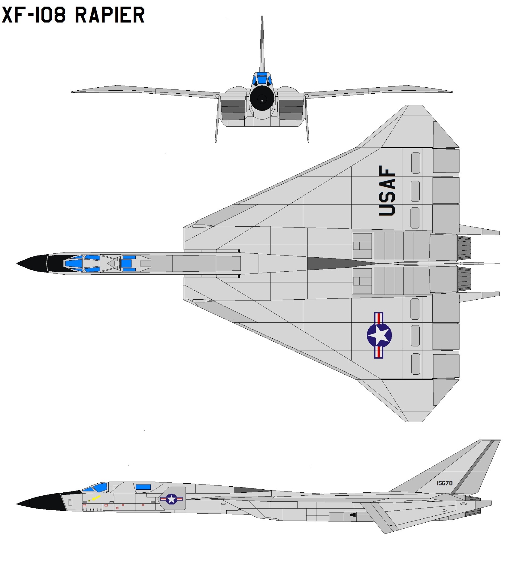
It was intended as a Cold War Mach 3 long range interceptor to stop Soviet bombers coming over the Pole.
Like the XB70 it would have been largely built from stainless steel.
A "mock up" was built.
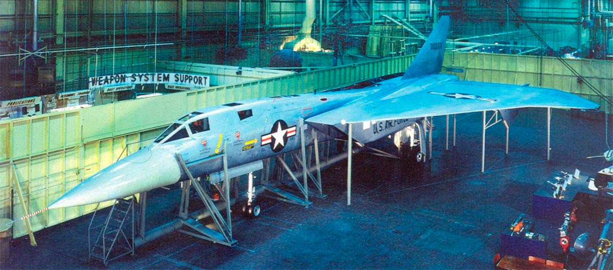
Intended to use the same engines as the XB70 however it soon became obvious that ICBMs would be the means of nuclear delivery so the XF108 was promptly cancelled. The XB70 development was allowed to continue as nuclear delivery at mach 3 and 70.000 feet still had possibilities until it became obvious that anti aircraft missiles had developed to make intercepts at such height and speed.
The XF108 should make a good EDF. A delta gives plenty of wing area and each inlet is of sufficient area to adequately feed an EDF when it is sized for the Mach 3 exhaust nozzle configuration.
Still thinking at this stage.
It was intended as a Cold War Mach 3 long range interceptor to stop Soviet bombers coming over the Pole.
Like the XB70 it would have been largely built from stainless steel.
A "mock up" was built.
Intended to use the same engines as the XB70 however it soon became obvious that ICBMs would be the means of nuclear delivery so the XF108 was promptly cancelled. The XB70 development was allowed to continue as nuclear delivery at mach 3 and 70.000 feet still had possibilities until it became obvious that anti aircraft missiles had developed to make intercepts at such height and speed.
The XF108 should make a good EDF. A delta gives plenty of wing area and each inlet is of sufficient area to adequately feed an EDF when it is sized for the Mach 3 exhaust nozzle configuration.
Still thinking at this stage.
Attachments:
Thanks: Klipkopwildlife, Flytilbroke, old ugly
Please Log in or Create an account to join the conversation.
- Quorneng
-
Topic Author
- Offline
- Forum Master
-
Less
More
- Posts: 10058
- Thank you received: 19043
27 Nov 2024 21:09 - 28 Nov 2024 07:10 #2
by Quorneng
Replied by Quorneng on topic A plane to go with my Depron XB70 Valkyrie
I have managed to purchase, but not yet delivered, two XFLY 12 blade 40 mm EDFs dirt cheap from Ali Express so I can start the construction of the XF108 in XPS 3mm sheet foam..
The only problem is every drawing I can find shows a slightly different configuration!
Apparently there was a formally "approved" layout but this occurred just a few weeks before all work was suspended prior to formal project cancellation.
On this basis what ever I build will be wrong.

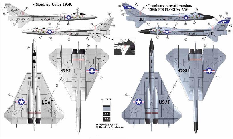
The only problem is every drawing I can find shows a slightly different configuration!
Apparently there was a formally "approved" layout but this occurred just a few weeks before all work was suspended prior to formal project cancellation.
On this basis what ever I build will be wrong.
Attachments:
Last edit: 28 Nov 2024 07:10 by Klipkopwildlife.
Thanks: Eric, Klipkopwildlife, Flytilbroke, old ugly
Please Log in or Create an account to join the conversation.
- Eric
-

- Offline
- Moderator
-

Less
More
- Posts: 15406
- Thank you received: 14306
28 Nov 2024 10:07 #3
by Eric
if you are calm and collected when all about you are going berserk - you've missed something important!
Replied by Eric on topic A plane to go with my Depron XB70 Valkyrie
As it appears to have a large sub-fin, perhaps it was unstable in yaw?
if you are calm and collected when all about you are going berserk - you've missed something important!
Thanks: Klipkopwildlife
Please Log in or Create an account to join the conversation.
- Quorneng
-
Topic Author
- Offline
- Forum Master
-
Less
More
- Posts: 10058
- Thank you received: 19043
28 Nov 2024 14:52 #4
by Quorneng
Replied by Quorneng on topic A plane to go with my Depron XB70 Valkyrie
It was never completed so we will never know.
A delta can tighten in roll when turning. Perhaps North American felt a substantial under fin would reduce this effect.
Perhaps a bit optimistic but as a fighter the F108 Rapier was intended to be able to maneuver at mach3.
Difficult ti imagine the inlet ducts would be able to keep the airflow subsonic to the compressor stage with any sort of change in airflow direction. After all the only successful mach3 planes were the XB70 and SR71 and they were intended to fly just straight and level at such speeds.
A delta can tighten in roll when turning. Perhaps North American felt a substantial under fin would reduce this effect.
Perhaps a bit optimistic but as a fighter the F108 Rapier was intended to be able to maneuver at mach3.
Difficult ti imagine the inlet ducts would be able to keep the airflow subsonic to the compressor stage with any sort of change in airflow direction. After all the only successful mach3 planes were the XB70 and SR71 and they were intended to fly just straight and level at such speeds.
Thanks: Eric, Klipkopwildlife
Please Log in or Create an account to join the conversation.
- Quorneng
-
Topic Author
- Offline
- Forum Master
-
Less
More
- Posts: 10058
- Thank you received: 19043
06 Dec 2024 11:09 - 06 Dec 2024 11:12 #5
by Quorneng
Replied by Quorneng on topic A plane to go with my Depron XB70 Valkyrie. The XF108 Rapier
Slowly working on how I might build the Rapier.
First simplify the 3 view to get closer to a line drawing.
The elevation.
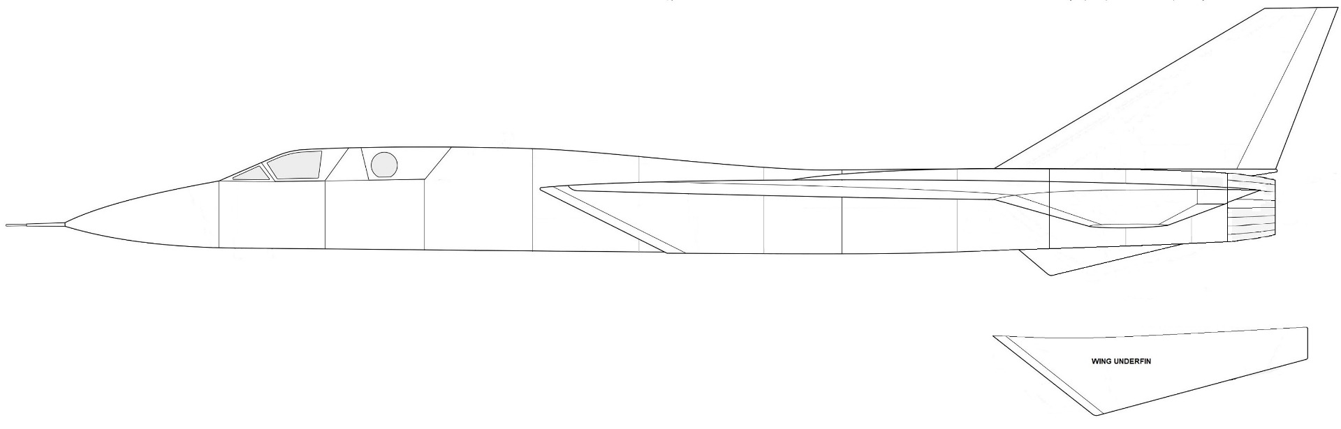
The fuselage is wide but long and shallow!
I intend to use two powerful 40 mm EDFs. Fortunately the intake has near the ideal area to feed an EDF suitable for a scale exhaust nozzle .
I note the jet pipe is prominently segmented. As with the duct it would be printed so I wondered what could be done.visually.There are 18 sections shown.
This is progress so far. It is in the fully closed "supersonic" configuration to give the appropriate nozzle area for the EDF..
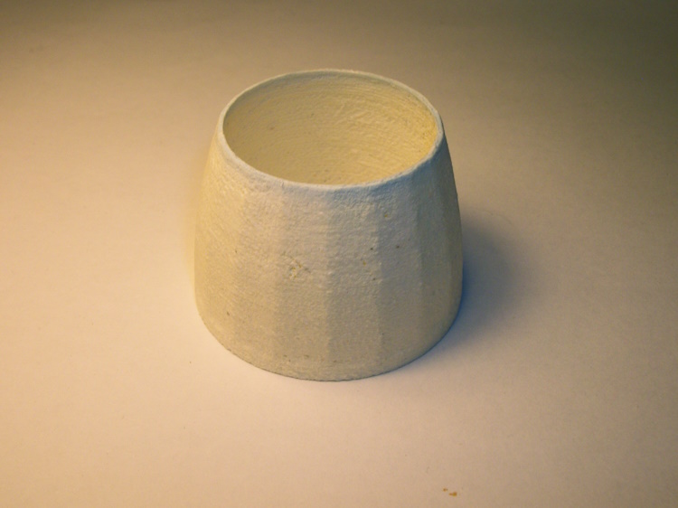
Printed in LW-PLA as it has quite a complex structure. It weighs 2.7g.
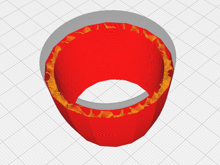
Inner and outer "lofted" 3 dimensional shapes with a gyroid infill between them. It is sized to fit on the end of a 40mm EDF, when I can afford to buy them!

First simplify the 3 view to get closer to a line drawing.
The elevation.
The fuselage is wide but long and shallow!
I intend to use two powerful 40 mm EDFs. Fortunately the intake has near the ideal area to feed an EDF suitable for a scale exhaust nozzle .
I note the jet pipe is prominently segmented. As with the duct it would be printed so I wondered what could be done.visually.There are 18 sections shown.
This is progress so far. It is in the fully closed "supersonic" configuration to give the appropriate nozzle area for the EDF..
Printed in LW-PLA as it has quite a complex structure. It weighs 2.7g.
Inner and outer "lofted" 3 dimensional shapes with a gyroid infill between them. It is sized to fit on the end of a 40mm EDF, when I can afford to buy them!
Attachments:
Last edit: 06 Dec 2024 11:12 by Quorneng.
Thanks: Eric, Klipkopwildlife, jon.in.swansea, old ugly
Please Log in or Create an account to join the conversation.
- Quorneng
-
Topic Author
- Offline
- Forum Master
-
Less
More
- Posts: 10058
- Thank you received: 19043
07 Dec 2024 11:50 #6
by Quorneng
Replied by Quorneng on topic A plane to go with my Depron XB70 Valkyrie
With the wind from storm Darragh howling outside I took the opportunity to do a bit more printing!
The first exhaust nozzle with its 18 sided polygon did not really highlight the individual sections so I hunted for a practical method to alter the polygon file to give a more distinct edge.
In FreeCAD the auto generated polygon file is clever but rather complex.
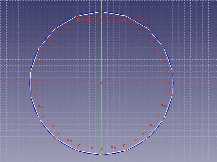
Almost any change to the file detail causes it to fail to work properly.
What did eventually prove possible without too much effort was to replace each flat side with a slight concave curve in the hope this would "emphasis" the edge of each section.
As the nozzle already had a separate smooth interior surface the more complex exterior would not alter its performance as an EDF nozzle.
A comparison of the two nozzles.
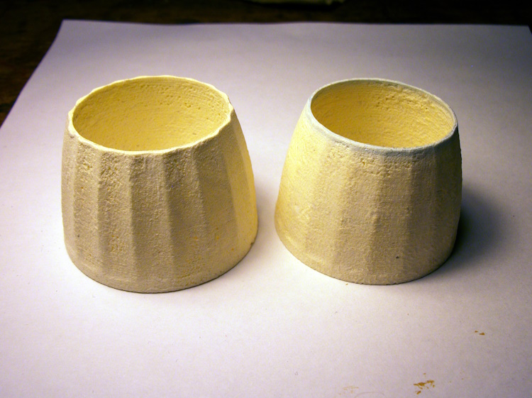
Whilst not exactly a true scale of a "petal" nozzle it certainly highlights each nozzle section.
I am happy with the result but it does represent a few hours of my life spent on achieving something that will make absolutely no difference to how the Rapier might fly if and when it does.
Not to worry it is what aeromodelling is all about.

The first exhaust nozzle with its 18 sided polygon did not really highlight the individual sections so I hunted for a practical method to alter the polygon file to give a more distinct edge.
In FreeCAD the auto generated polygon file is clever but rather complex.
Almost any change to the file detail causes it to fail to work properly.
What did eventually prove possible without too much effort was to replace each flat side with a slight concave curve in the hope this would "emphasis" the edge of each section.
As the nozzle already had a separate smooth interior surface the more complex exterior would not alter its performance as an EDF nozzle.
A comparison of the two nozzles.
Whilst not exactly a true scale of a "petal" nozzle it certainly highlights each nozzle section.
I am happy with the result but it does represent a few hours of my life spent on achieving something that will make absolutely no difference to how the Rapier might fly if and when it does.
Not to worry it is what aeromodelling is all about.
Attachments:
Thanks: Eric, Klipkopwildlife, jon.in.swansea
Please Log in or Create an account to join the conversation.
- Quorneng
-
Topic Author
- Offline
- Forum Master
-
Less
More
- Posts: 10058
- Thank you received: 19043
09 Dec 2024 15:41 - 09 Dec 2024 15:49 #7
by Quorneng
Replied by Quorneng on topic A plane to go with my Depron XB70 Valkyrie
Nothing very "concrete" towards progress but I have generated the sections of the full length of the duct for the Rapier. The EDF goes in the gap.
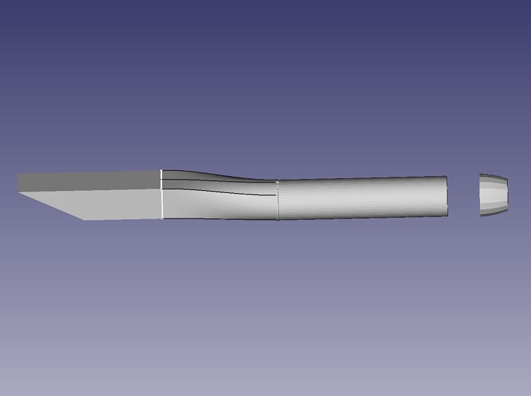
Only a CAD image of the right hand duct as I don't want to actually print anything until I have the 40mm EDFs to check it fits.
Only the centre bit of the duct is "handed". The other parts are common.
Printed in single wall LW-PLA the duct will rely entirely of the fuselage formers to prevent collapsing under the inlet low pressure. How to achieve this during the actual fuselage construction I have no idea. yet!
Absolutely nothing to do with RC planes but I bet you will never guess or believe what this thing is to be used for. I have just designed and printed it!
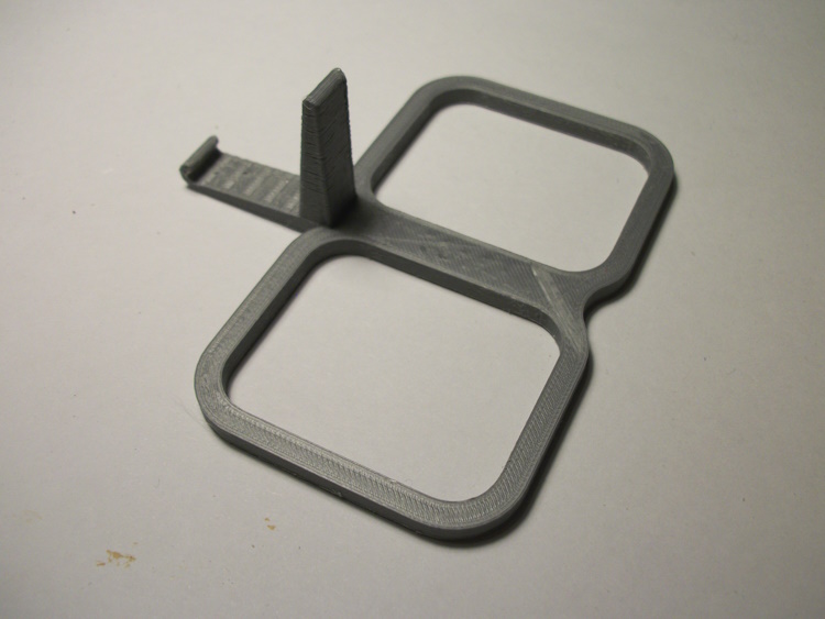
It goes into a car.
Answer next time.
Only a CAD image of the right hand duct as I don't want to actually print anything until I have the 40mm EDFs to check it fits.
Only the centre bit of the duct is "handed". The other parts are common.
Printed in single wall LW-PLA the duct will rely entirely of the fuselage formers to prevent collapsing under the inlet low pressure. How to achieve this during the actual fuselage construction I have no idea. yet!
Absolutely nothing to do with RC planes but I bet you will never guess or believe what this thing is to be used for. I have just designed and printed it!
It goes into a car.
Answer next time.
Attachments:
Last edit: 09 Dec 2024 15:49 by Quorneng.
Thanks: Eric, Klipkopwildlife, Flytilbroke
Please Log in or Create an account to join the conversation.
- Magpie
-

- Offline
- Elite Member
-

Less
More
- Posts: 587
- Thank you received: 1047
09 Dec 2024 16:44 #8
by Magpie
Replied by Magpie on topic A plane to go with my Depron XB70 Valkyrie
You should have called the photo Mystery Object not Double Pot Holder.
Do Pot Noodles come in square tubs in your neck of the woods?
Do Pot Noodles come in square tubs in your neck of the woods?
Thanks: Klipkopwildlife
Please Log in or Create an account to join the conversation.
- Quorneng
-
Topic Author
- Offline
- Forum Master
-
Less
More
- Posts: 10058
- Thank you received: 19043
09 Dec 2024 23:24 #9
by Quorneng
Replied by Quorneng on topic A plane to go with my Depron XB70 Valkyrie
I did wonder if anyone would spot that.
Not for Pot noodle but McDonalds sauce pots!
It is designed to clip into the grill of a dashboard centre air vent (for a particular car) so you have somewhere to put the pots while you dip your fries.
I hasten to add it is not for me. I am under doctors orders with a diabetes prevention diet. No McDonalds for me!
Not for Pot noodle but McDonalds sauce pots!
It is designed to clip into the grill of a dashboard centre air vent (for a particular car) so you have somewhere to put the pots while you dip your fries.
I hasten to add it is not for me. I am under doctors orders with a diabetes prevention diet. No McDonalds for me!
Thanks: Eric, Klipkopwildlife
Please Log in or Create an account to join the conversation.
- Quorneng
-
Topic Author
- Offline
- Forum Master
-
Less
More
- Posts: 10058
- Thank you received: 19043
12 Dec 2024 19:27 #10
by Quorneng
Replied by Quorneng on topic A plane to go with my Depron XB70 Valkyrie
Just a bit more of the printed duct. The inlet section in LW-PLA.
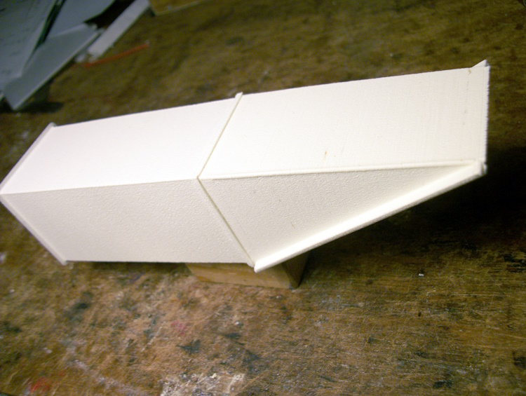
It is actually in two parts that fit together.
The rectangular rear part is single wall "vase" printed whereas the intake has a double wall and incorporates a radius leading edge to provide some stiffness against being sucked in.
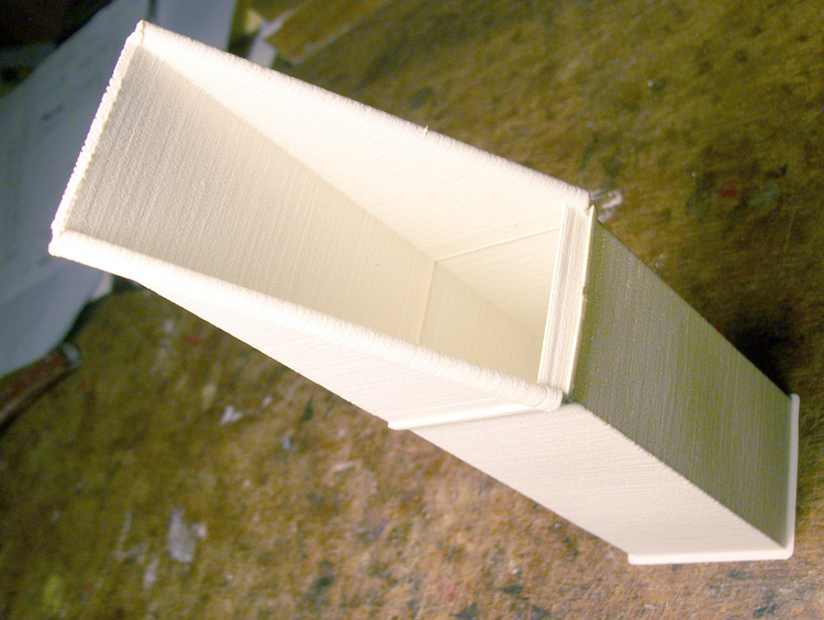
When built into the airframe this part of the duct will in effect be clad in 3mm sheet foam.
The next part of the duct translates from a rectangle to a circle. The final circle diameter will be set to exactly match both the internal diameter of the EDF as well as having a lip so it can be glued on. This requires a bit of trial and error dimension testing particularly in LW-PLA where due to the foaming the "as printed" size is not quite the same as the figure in the CAD file.. I am still awaiting delivery of the 40mm EDF!
It is actually in two parts that fit together.
The rectangular rear part is single wall "vase" printed whereas the intake has a double wall and incorporates a radius leading edge to provide some stiffness against being sucked in.
When built into the airframe this part of the duct will in effect be clad in 3mm sheet foam.
The next part of the duct translates from a rectangle to a circle. The final circle diameter will be set to exactly match both the internal diameter of the EDF as well as having a lip so it can be glued on. This requires a bit of trial and error dimension testing particularly in LW-PLA where due to the foaming the "as printed" size is not quite the same as the figure in the CAD file.. I am still awaiting delivery of the 40mm EDF!
Attachments:
Thanks: Eric, Klipkopwildlife
Please Log in or Create an account to join the conversation.
- Quorneng
-
Topic Author
- Offline
- Forum Master
-
Less
More
- Posts: 10058
- Thank you received: 19043
15 Dec 2024 22:54 #11
by Quorneng
Replied by Quorneng on topic A plane to go with my Depron XB70 Valkyrie
After nearly 4 hours of printing the LH duct at full length over the full size plan.
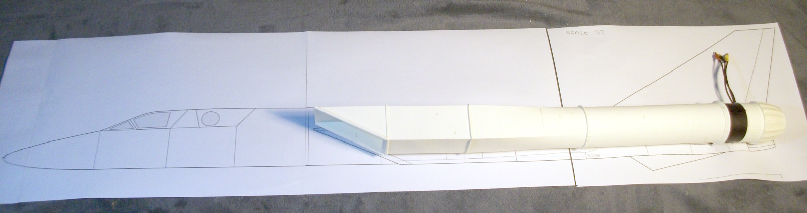
It looks an awful lot of duct for a tiny EDF although it is a 12 blade XFLY 40mm.
Now to do it all over again for the RH duct/
Not such a big task second time round as the bits should all fit together exactly..
It looks an awful lot of duct for a tiny EDF although it is a 12 blade XFLY 40mm.
Now to do it all over again for the RH duct/
Not such a big task second time round as the bits should all fit together exactly..
Attachments:
Thanks: Eric, Klipkopwildlife, jon.in.swansea, old ugly
Please Log in or Create an account to join the conversation.
- Quorneng
-
Topic Author
- Offline
- Forum Master
-
Less
More
- Posts: 10058
- Thank you received: 19043
25 Dec 2024 23:20 - 25 Dec 2024 23:21 #12
by Quorneng
Replied by Quorneng on topic A plane to go with my Depron XB70 Valkyrie
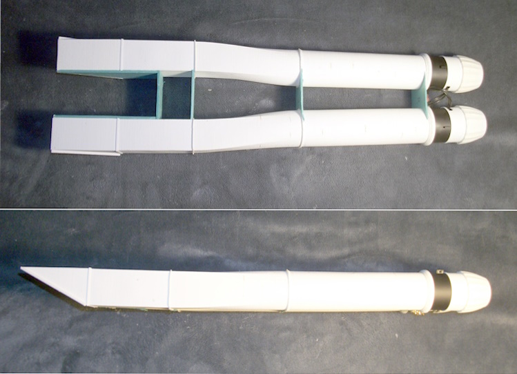
Now finished printing all the bits for bot ducts and the second 40mm XFLY EDF has arrived so the complete duct trial assembled.
Top and side views
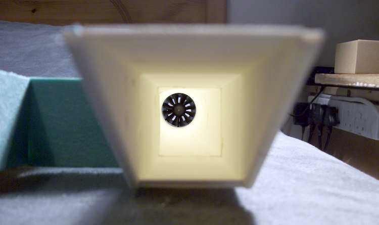
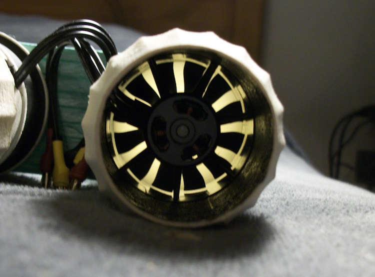
More for my own record than of particular interest views looking down the inlet and nozzle.
Now I will have to start seriously thinking about building up the fuselage shape. Not that easy as I have no cross sections at all to work from!
The object will be to leave open the upper surface between the ducts to run the EDF wires.
Top and side views
More for my own record than of particular interest views looking down the inlet and nozzle.
Now I will have to start seriously thinking about building up the fuselage shape. Not that easy as I have no cross sections at all to work from!
The object will be to leave open the upper surface between the ducts to run the EDF wires.
Attachments:
Last edit: 25 Dec 2024 23:21 by Quorneng.
Thanks: Eric, Klipkopwildlife, jon.in.swansea
Please Log in or Create an account to join the conversation.
- Quorneng
-
Topic Author
- Offline
- Forum Master
-
Less
More
- Posts: 10058
- Thank you received: 19043
27 Dec 2024 15:53 - 27 Dec 2024 15:53 #13
by Quorneng
Replied by Quorneng on topic A plane to go with my Depron XB70 Valkyrie
I have built up and added a skin to the sides and bottom of the duct.
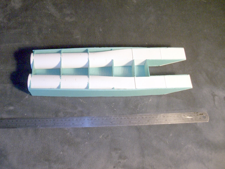
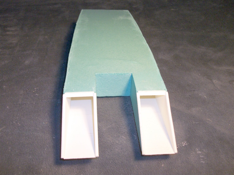
Its light & remarkably stiff even though still open topped BUT........
I am now convinced it is simply too small!
Although the 40 mm EDFs are light & powerful but with a thin flat narrow delta wing of only 24" span it will fly seriously fast and as a result have very limited crash resistance.
After all the bigger 40" DH Venom with a straight wing uses a single 40 mm EDF and that is no slouch.
My intention is to start again but increase the size by 50%. Even than it will still only have a 36" span but as the ducts will be the same diameter it will be easier to incorporate them in the bigger fuselage. At least what I have done so far gives confidence that the construction technique chosen is viable.
We shall see but the perhaps I should make it even bigger.
Its light & remarkably stiff even though still open topped BUT........
I am now convinced it is simply too small!
Although the 40 mm EDFs are light & powerful but with a thin flat narrow delta wing of only 24" span it will fly seriously fast and as a result have very limited crash resistance.
After all the bigger 40" DH Venom with a straight wing uses a single 40 mm EDF and that is no slouch.
My intention is to start again but increase the size by 50%. Even than it will still only have a 36" span but as the ducts will be the same diameter it will be easier to incorporate them in the bigger fuselage. At least what I have done so far gives confidence that the construction technique chosen is viable.
We shall see but the perhaps I should make it even bigger.
Attachments:
Last edit: 27 Dec 2024 15:53 by Quorneng.
Thanks: Eric, Klipkopwildlife, Flytilbroke, jon.in.swansea
Please Log in or Create an account to join the conversation.
- Quorneng
-
Topic Author
- Offline
- Forum Master
-
Less
More
- Posts: 10058
- Thank you received: 19043
29 Dec 2024 15:12 #14
by Quorneng
Replied by Quorneng on topic The XF108A Rapier to go with my XB70 Valkyrie
A bit house bound at the moment. Because of my diabetes I need the consultants signed approval to submit to the DVLA in order to legally continue to drive!
So I have the time to design the duct work for the 50% bigger XF108.

A CAD image "plan view" of the pair of ducts and an "elevation view" together showing both the vertical and horizontal offset along the duct.
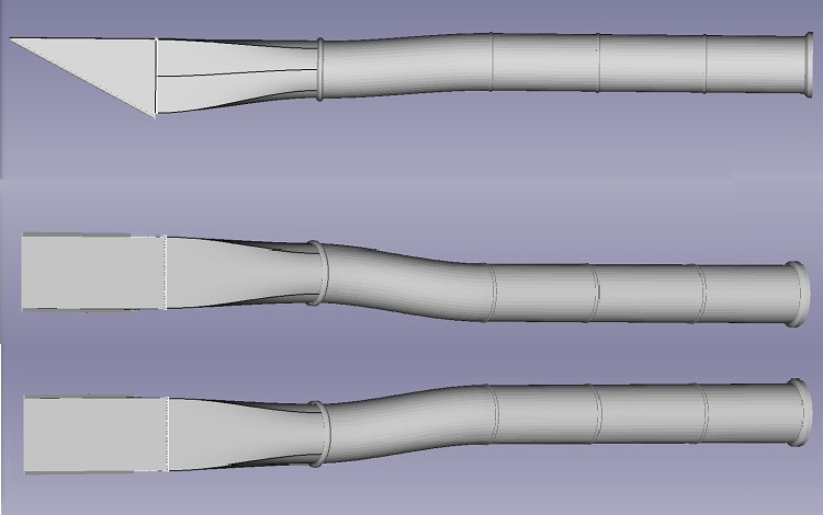
To keep each part well within the printer volume it is now made up of 6 rather than 4 components that are eventually glued together..There is also the EDF exhaust nozzle to go on after each EDF.
The neat trick is there are no longer any left or right hand bits. All the parts are common to either duct.
For both ducts it represents a total of just over 12 hours of single wall LW-PLA printing.
A 50% bigger inlet looks er big!
So I have the time to design the duct work for the 50% bigger XF108.
A CAD image "plan view" of the pair of ducts and an "elevation view" together showing both the vertical and horizontal offset along the duct.
To keep each part well within the printer volume it is now made up of 6 rather than 4 components that are eventually glued together..There is also the EDF exhaust nozzle to go on after each EDF.
The neat trick is there are no longer any left or right hand bits. All the parts are common to either duct.
For both ducts it represents a total of just over 12 hours of single wall LW-PLA printing.
A 50% bigger inlet looks er big!
Attachments:
Thanks: Eric, Klipkopwildlife, Flytilbroke, jon.in.swansea
Please Log in or Create an account to join the conversation.
- Quorneng
-
Topic Author
- Offline
- Forum Master
-
Less
More
- Posts: 10058
- Thank you received: 19043
01 Jan 2025 20:50 #15
by Quorneng
Replied by Quorneng on topic A plane to go with my Depron XB70 Valkyrie
Slowly printing the first set of parts for one of the ducts for the50% bigger XF108..
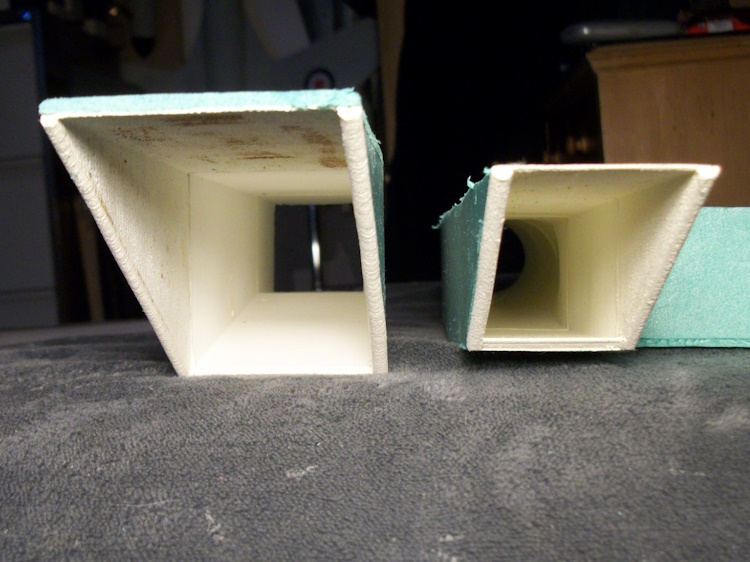
A comparison of the big and small.

Although much of the duct is basically the same the actual inlet and EDF nozzle are quite a bit more "generous"!
To account for the smaller duct diameter the exhaust petals have had to to contracted down to a below scale diameter.

A bit "over the top" for scale but rather than using dished petals to give the impression of "segments" the bigger one has flat segments that are actually overlapped!
Very tedious to set up in CAD. Just as well I have the time at the moment.

A comparison of the big and small.
Although much of the duct is basically the same the actual inlet and EDF nozzle are quite a bit more "generous"!
To account for the smaller duct diameter the exhaust petals have had to to contracted down to a below scale diameter.
A bit "over the top" for scale but rather than using dished petals to give the impression of "segments" the bigger one has flat segments that are actually overlapped!
Very tedious to set up in CAD. Just as well I have the time at the moment.
Attachments:
Thanks: Eric, Klipkopwildlife, Flytilbroke, jon.in.swansea, old ugly
Please Log in or Create an account to join the conversation.
Time to create page: 0.313 seconds