
- Posts: 10058
- Thank you received: 19043
Printing with Light Weight PLA
- Quorneng
-
 Topic Author
- Offline
- Forum Master
-

Less
More
22 Feb 2023 11:11 #16
by Quorneng
Replied by Quorneng on topic Printing with Light Weight PLA
When I first started 3D printing I experimented printing a complete wing section in PLA using an internal 'fill' to support the wing skin.

The intention was that all the loads would be carried by the skin.
It worked but the wing was relatively heavy even with even a single 0.3 mm wall. Printed vertically a Clark Y section with a 170 mm chord and a 240 mm span would weigh 67g and take the best part of 7 hours to print. Although printing vertically gives by far the best print quality the wing bending forces would be across the print layers. A direction that has less than half the tensile strength compared to along the line of print.
A carbon spar could provide the necessary bending strength but the "easy to programme" fill would be partly redundant so would just add significant weight.
Such a wing fell well short of the strength to weight that could be achieved with reinforced foam and Depron in particular.
With LW-PLA I wondered if the "fill" concept could be revisited.
The basic flexibility of LW-PLA would mean the wing would need a carbon spar reinforcement to resist bending but there would be a considerable weight saving provided the wing exhibited sufficient torsional rigidity.
The same Clark Y but printed in LW-PLA.

Now only 37g for a 240 mm span wing but the slower print speed means 10 hours printing.
the latest CURA version has an additional fill type "Gyroid". Being an automatically generated 3 dimensional fill it does provide better torsional rigidity for the same weight.
 .
.
Still 37 g but the more complex print fill means 11 hours printing.
Not wishing to undertake such long prints I set up a 50 mm span wing at half scale with both types of infill.

The result is surprisingly good although each takes 45 minutes to print.

As I expected the "Gyroid" infill is a bit more rigid torsionally and has a slightly blander surface.
Of course not being a continuous print there are many "tails" but they are all internal within the wing.
One further point is LW-PLA has much better across the print layer strength than PLA so it is possible the outer panels may need no reinforcement.
The only down side is the long print times, over 40 hours for a 4 section wing with a 960 mm span.
I suppose it all comes down to a personal preference on how you want to make your planes.
.
The intention was that all the loads would be carried by the skin.
It worked but the wing was relatively heavy even with even a single 0.3 mm wall. Printed vertically a Clark Y section with a 170 mm chord and a 240 mm span would weigh 67g and take the best part of 7 hours to print. Although printing vertically gives by far the best print quality the wing bending forces would be across the print layers. A direction that has less than half the tensile strength compared to along the line of print.
A carbon spar could provide the necessary bending strength but the "easy to programme" fill would be partly redundant so would just add significant weight.
Such a wing fell well short of the strength to weight that could be achieved with reinforced foam and Depron in particular.
With LW-PLA I wondered if the "fill" concept could be revisited.
The basic flexibility of LW-PLA would mean the wing would need a carbon spar reinforcement to resist bending but there would be a considerable weight saving provided the wing exhibited sufficient torsional rigidity.
The same Clark Y but printed in LW-PLA.
Now only 37g for a 240 mm span wing but the slower print speed means 10 hours printing.
the latest CURA version has an additional fill type "Gyroid". Being an automatically generated 3 dimensional fill it does provide better torsional rigidity for the same weight.
Still 37 g but the more complex print fill means 11 hours printing.
Not wishing to undertake such long prints I set up a 50 mm span wing at half scale with both types of infill.
The result is surprisingly good although each takes 45 minutes to print.
As I expected the "Gyroid" infill is a bit more rigid torsionally and has a slightly blander surface.
Of course not being a continuous print there are many "tails" but they are all internal within the wing.
One further point is LW-PLA has much better across the print layer strength than PLA so it is possible the outer panels may need no reinforcement.
The only down side is the long print times, over 40 hours for a 4 section wing with a 960 mm span.
I suppose it all comes down to a personal preference on how you want to make your planes.
.
Attachments:
Thanks: Klipkopwildlife, jon.in.swansea
Please Log in or Create an account to join the conversation.
- jon.in.swansea
-

- Offline
- Elite Member
-

Less
More
- Posts: 757
- Thank you received: 1164
22 Feb 2023 16:22 #17
by jon.in.swansea
Replied by jon.in.swansea on topic Printing with Light Weight PLA
When I was converting the PLA rib to a LW-PLA rib I increase the depth of the print from 3mm to 5mm - that gave more surface area to the flanges and increase the stiffness without having to put a top on it. I also went from 1 base layer to 2 base layers which also helped to stiffen it up.
I have been playing around with getting some diagonal ribs into my wing - goodness what a merry chase that lead me on. Some images soon.
I have been playing around with getting some diagonal ribs into my wing - goodness what a merry chase that lead me on. Some images soon.
Please Log in or Create an account to join the conversation.
- jon.in.swansea
-
- Offline
- Elite Member
-
Less
More
- Posts: 757
- Thank you received: 1164
22 Feb 2023 17:17 #18
by jon.in.swansea
Replied by jon.in.swansea on topic Printing with Light Weight PLA
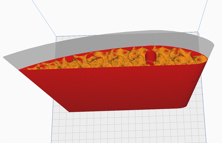
I tried to make my printed-spars-only LW-PLA wing end work better by applying a diagonal grid of cuts to the skin. Here
is the grid.

When I went to slice it in Vase mode I got a not-printable abstract work of art....

I then went exploring.... after a half dozen iterations I found that vertical cuts and diagonal cuts do not like to mix. I eventually decided to leave the leading edge of the wing up to the spar as vertical spars and confine the diagonals to the trailing section.

Another half dozen iterations and I worked out how to hollow out the diagonals while not messing up other stuff.

The printed spars version was 14.4g and the with-diagonals (below) is 17.3g.


With diagonals seems stiffer to the touch. Lots of work to get that though.
is the grid.
When I went to slice it in Vase mode I got a not-printable abstract work of art....
I then went exploring.... after a half dozen iterations I found that vertical cuts and diagonal cuts do not like to mix. I eventually decided to leave the leading edge of the wing up to the spar as vertical spars and confine the diagonals to the trailing section.
Another half dozen iterations and I worked out how to hollow out the diagonals while not messing up other stuff.
The printed spars version was 14.4g and the with-diagonals (below) is 17.3g.
With diagonals seems stiffer to the touch. Lots of work to get that though.
Attachments:
Thanks: Klipkopwildlife
Please Log in or Create an account to join the conversation.
- Quorneng
-
Topic Author
- Offline
- Forum Master
-
Less
More
- Posts: 10058
- Thank you received: 19043
22 Feb 2023 18:56 #19
by Quorneng
Replied by Quorneng on topic Printing with Light Weight PLA
jon
Fascinating stuff.
That diagonal internal bracing looks pretty similar to the type of wing construction used by Plane Print.
Obviously if your intention is to make the final STL files available for sale then almost any amount of work can be justified but as a one off own build there must b a point where conventional construction becomes more attractive.
Fascinating stuff.
That diagonal internal bracing looks pretty similar to the type of wing construction used by Plane Print.
Obviously if your intention is to make the final STL files available for sale then almost any amount of work can be justified but as a one off own build there must b a point where conventional construction becomes more attractive.
Thanks: Klipkopwildlife, jon.in.swansea
Please Log in or Create an account to join the conversation.
- Klipkopwildlife
-

- Offline
- Administrator
-

- I'm supposed to be retired!
23 Feb 2023 07:23 #20
by Klipkopwildlife
Do it now, you may never get another chance
Replied by Klipkopwildlife on topic Printing with Light Weight PLA
Jon has promised me some one on one training while he's here, I'm really looking forward to it.

Do it now, you may never get another chance
Please Log in or Create an account to join the conversation.
- jon.in.swansea
-
- Offline
- Elite Member
-
Less
More
- Posts: 757
- Thank you received: 1164
23 Feb 2023 15:07 - 23 Feb 2023 15:08 #21
by jon.in.swansea
Replied by jon.in.swansea on topic Printing with Light Weight PLA
I suppose I am essentially curious about how one might drive a CAD package to reduce the stringing. And also the end-of-wing with ailerons is so fiddly in a hybrid of foam and printed ribs that it seemed worth the try. I can get the taper of the thickness down much more than with the hybrid. The rest of the wing I think I will use LW-PLA ribs (having sorted that) along with a CF spar.
I did take my oval fuselage and switched over to the LW-PLA and kept the gyroid 5% infil and it printed out very nice indeed. Roughly 1/3 the weight but with the engine mount in PLA the whole beastie of a fuselage comes out a bit less than half the original weight - that 40-45g should help greatly towards my goal of a slow flying park flyer.
Ah - A QUESTION - I have never painted any printed parts. But if there is some 'wing skin' as LW-PLA it seems to me it might be sensitive to wet grass in terms of picking up weight. What do folk recommend for a 'rain coating'?
I did take my oval fuselage and switched over to the LW-PLA and kept the gyroid 5% infil and it printed out very nice indeed. Roughly 1/3 the weight but with the engine mount in PLA the whole beastie of a fuselage comes out a bit less than half the original weight - that 40-45g should help greatly towards my goal of a slow flying park flyer.
Ah - A QUESTION - I have never painted any printed parts. But if there is some 'wing skin' as LW-PLA it seems to me it might be sensitive to wet grass in terms of picking up weight. What do folk recommend for a 'rain coating'?
Last edit: 23 Feb 2023 15:08 by jon.in.swansea.
Please Log in or Create an account to join the conversation.
- Klipkopwildlife
-
- Offline
- Administrator
-
- I'm supposed to be retired!
23 Feb 2023 16:51 #22
by Klipkopwildlife
Do it now, you may never get another chance
Replied by Klipkopwildlife on topic Printing with Light Weight PLA
I would be tempted to use a light coating of hair laquer.
Do it now, you may never get another chance
Thanks: jon.in.swansea
Please Log in or Create an account to join the conversation.
- Quorneng
-
Topic Author
- Offline
- Forum Master
-
Less
More
- Posts: 10058
- Thank you received: 19043
23 Feb 2023 18:18 #23
by Quorneng
Replied by Quorneng on topic Printing with Light Weight PLA
jon
Mud/grass stains on LW=PLA will dry out but it remains very "dirty".
Any water based acrylic paint will provide protection as it "fills" the surface.
A light follow up acrylic clear spray will give almost a washabke (within reason!) surface..
Mud/grass stains on LW=PLA will dry out but it remains very "dirty".
Any water based acrylic paint will provide protection as it "fills" the surface.
A light follow up acrylic clear spray will give almost a washabke (within reason!) surface..
Thanks: Flytilbroke, jon.in.swansea
Please Log in or Create an account to join the conversation.
- jon.in.swansea
-
- Offline
- Elite Member
-
Less
More
- Posts: 757
- Thank you received: 1164
24 Feb 2023 10:35 #24
by jon.in.swansea
Replied by jon.in.swansea on topic Printing with Light Weight PLA
About joining those EDF duct sections - I assume there is some overlap of the sections e.g one forming a flange over the next section for gluing area or are you just gluing them end to end (which seems like a tiny contact area which would be a weak point in a wing?
Please Log in or Create an account to join the conversation.
- jon.in.swansea
-
- Offline
- Elite Member
-
Less
More
- Posts: 757
- Thank you received: 1164
24 Feb 2023 10:53 #25
by jon.in.swansea
Replied by jon.in.swansea on topic Printing with Light Weight PLA
I have tried another couple of variants of the wing end. One where I include the same kind of oval voids as in the LW-PLA ribs and then include a 3% gyroid infil. That resulted in a rather stiff wing but the weight was up 10g from the vase mode. The stringing was painful to watch. The voids were full of the little blighters. And it took two hours longer to print.


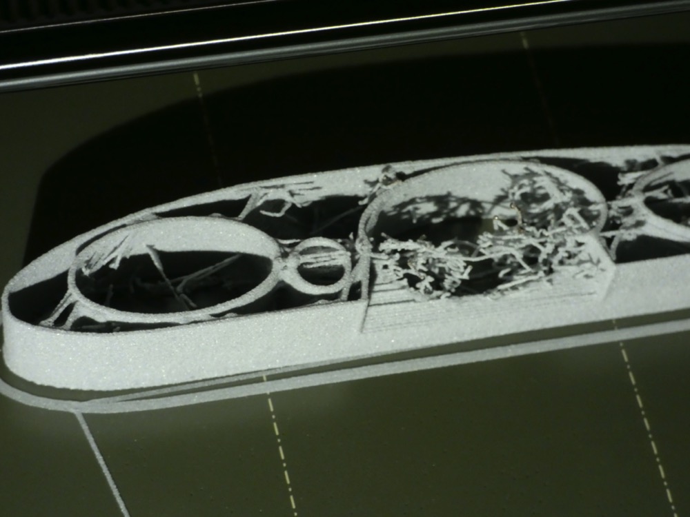
Although it is dead ugly I did get a smile when I found I could take the whole wing and then slice off the aileron with a nice 40 degree cut. It tapers with the wing which was the really difficult thing to do with individual ribs and foam. I can tape-hinge the upper face of the wing and aileron.
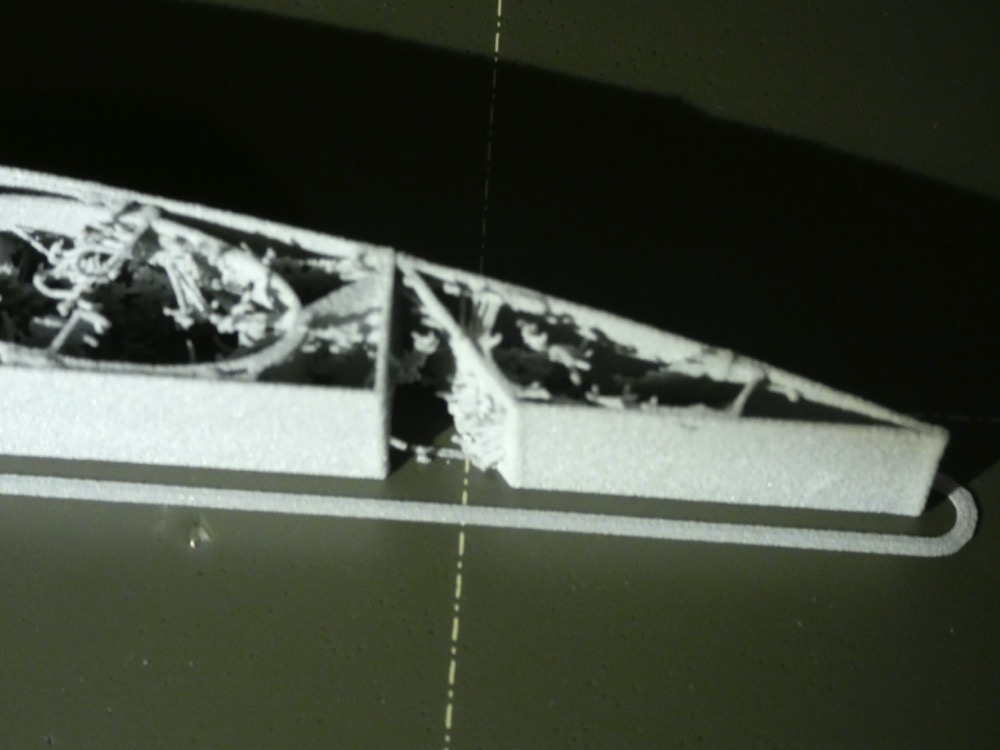
I think the added voids are not worth it in a wing although they might make sense in a rib. If I have only the spar and then a 3% gyroid infil the slicer estimates an hour off the print time.
-Jon
Although it is dead ugly I did get a smile when I found I could take the whole wing and then slice off the aileron with a nice 40 degree cut. It tapers with the wing which was the really difficult thing to do with individual ribs and foam. I can tape-hinge the upper face of the wing and aileron.
I think the added voids are not worth it in a wing although they might make sense in a rib. If I have only the spar and then a 3% gyroid infil the slicer estimates an hour off the print time.
-Jon
Attachments:
Thanks: Klipkopwildlife, Quorneng
Please Log in or Create an account to join the conversation.
- Quorneng
-
Topic Author
- Offline
- Forum Master
-
Less
More
- Posts: 10058
- Thank you received: 19043
24 Feb 2023 12:10 #26
by Quorneng
Replied by Quorneng on topic Printing with Light Weight PLA
jon
Not in your league of CAD design but my favoured 'simple' approach.
A Clark Y 50mm test wing printed on the face of the spar so the filaments run along the span.
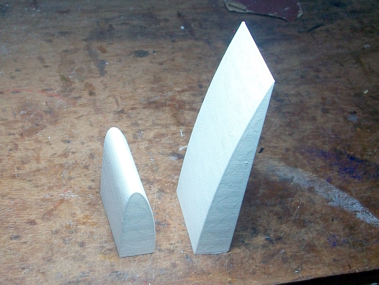
The total chord 175 mm and it weighs 7.6g in LW-PLA.
Once the fore and aft wing sections are created in Free Cad it is very simple to print.
The infill is 5% gyroid.

The result is remarkably stiff such that I believe a light weight wing up to 800 mm span might not need any reinforcement at all although it would be no problem to include space for a CF spar.
A further advantage of the print bead running span wise is the ailerons will be much stiffer too.
A shrouded aileron?

Being a flat bottom Clark Y the aileron can be printed on its lower surface.

Print time is still an issue. To print both the nose and tail wing section at 240 mm long is going to take the best part of 11 hours!
So far all my attempts to speed up the printing have resulted in print quality issues.
Still "thinking" before I actually try a full 4 section (960mm?) span wing.
Not in your league of CAD design but my favoured 'simple' approach.
A Clark Y 50mm test wing printed on the face of the spar so the filaments run along the span.
The total chord 175 mm and it weighs 7.6g in LW-PLA.
Once the fore and aft wing sections are created in Free Cad it is very simple to print.
The infill is 5% gyroid.
The result is remarkably stiff such that I believe a light weight wing up to 800 mm span might not need any reinforcement at all although it would be no problem to include space for a CF spar.
A further advantage of the print bead running span wise is the ailerons will be much stiffer too.
A shrouded aileron?
Being a flat bottom Clark Y the aileron can be printed on its lower surface.
Print time is still an issue. To print both the nose and tail wing section at 240 mm long is going to take the best part of 11 hours!
So far all my attempts to speed up the printing have resulted in print quality issues.
Still "thinking" before I actually try a full 4 section (960mm?) span wing.
Attachments:
Thanks: Klipkopwildlife, jon.in.swansea
Please Log in or Create an account to join the conversation.
- jon.in.swansea
-
- Offline
- Elite Member
-
Less
More
- Posts: 757
- Thank you received: 1164
26 Feb 2023 10:26 #27
by jon.in.swansea
Replied by jon.in.swansea on topic Printing with Light Weight PLA
Although some of my attempts at vase mode printing required pedantic iteration sometimes it is quite simple to convert from a slicer-generated infil to a vase print generated infil.
I took the aileron that I cut out of the general loft of the Clarke-Y. The lower face is flat so I can create a rectangular shape 0.1mm thick in FreeCAD and start it 0.7-0.8mm above the lower face and slicing through the upper face of the aileron add a track into the interior of the part. When it prints the path of the rectangular cut-out is close enough for the LW-PLA tracks to merge.

Here is a photo of the aileron with a 3% gyroid infil. There is some internal stringing and the weight is 5.1g.

Here is a photo printing in vase mode and it come in at 4.2g. It feels just a tiny bit less stiff.

I did print the vase mode with a couple of base layers to close off the end of the aileron so side-by-side they look similar.

So some shapes I think I will tend to go for the vase option during the design phase.
I took the aileron that I cut out of the general loft of the Clarke-Y. The lower face is flat so I can create a rectangular shape 0.1mm thick in FreeCAD and start it 0.7-0.8mm above the lower face and slicing through the upper face of the aileron add a track into the interior of the part. When it prints the path of the rectangular cut-out is close enough for the LW-PLA tracks to merge.
Here is a photo of the aileron with a 3% gyroid infil. There is some internal stringing and the weight is 5.1g.
Here is a photo printing in vase mode and it come in at 4.2g. It feels just a tiny bit less stiff.
I did print the vase mode with a couple of base layers to close off the end of the aileron so side-by-side they look similar.
So some shapes I think I will tend to go for the vase option during the design phase.
Attachments:
Thanks: Klipkopwildlife
Please Log in or Create an account to join the conversation.
- jon.in.swansea
-
- Offline
- Elite Member
-
Less
More
- Posts: 757
- Thank you received: 1164
26 Feb 2023 10:35 #28
by jon.in.swansea
Replied by jon.in.swansea on topic Printing with Light Weight PLA
Simple can be good. Getting to 'simple enough' is an interesting path. The single thin cut-out in the aileron probably counts as 'simple enough'.
I do worry about printing the aileron flat with a gyroid infil - I am finding is that near-horizontal LW-PLA is rather pathetic at bridging. Beyond a few mm it just drops. I suspect the upper face of a flat printed aileron with a low infil density will be quite lumpy.
I do worry about printing the aileron flat with a gyroid infil - I am finding is that near-horizontal LW-PLA is rather pathetic at bridging. Beyond a few mm it just drops. I suspect the upper face of a flat printed aileron with a low infil density will be quite lumpy.
Thanks: Klipkopwildlife
Please Log in or Create an account to join the conversation.
- jon.in.swansea
-
- Offline
- Elite Member
-
Less
More
- Posts: 757
- Thank you received: 1164
26 Feb 2023 12:47 #29
by jon.in.swansea
Replied by jon.in.swansea on topic Printing with Light Weight PLA
Further evolution of the Clarke-Y.... looking into that rather interesting idea of printing LW-PLA at 90 degrees. I took the Loft of the Clarke-Y and cut it in two parts along the line of the CT spar. I concentrated on the trailing portion and tried various thin-box cut-outs to impose some vase-mode ribs. I tried various cut-outs. One must very carefully review the preview of the slicer. If the slices are a bit close the 'trace' gets confused and whole sections of the print get lost during slicing.
As with the aileron, these very thin boxes start 0.8mm above the base of the wing. I kept them a few mm away from the CT to keep them from fighting in the slicer.
I also tried the idea of setting it on the print bed at a diagonal so I could get 220mm of length - thus I could also incude about 40mm of full cord along with the section for the aileron.

I kept the indentation for the servo on the lower face. Here is the print part-way. So clean inside!
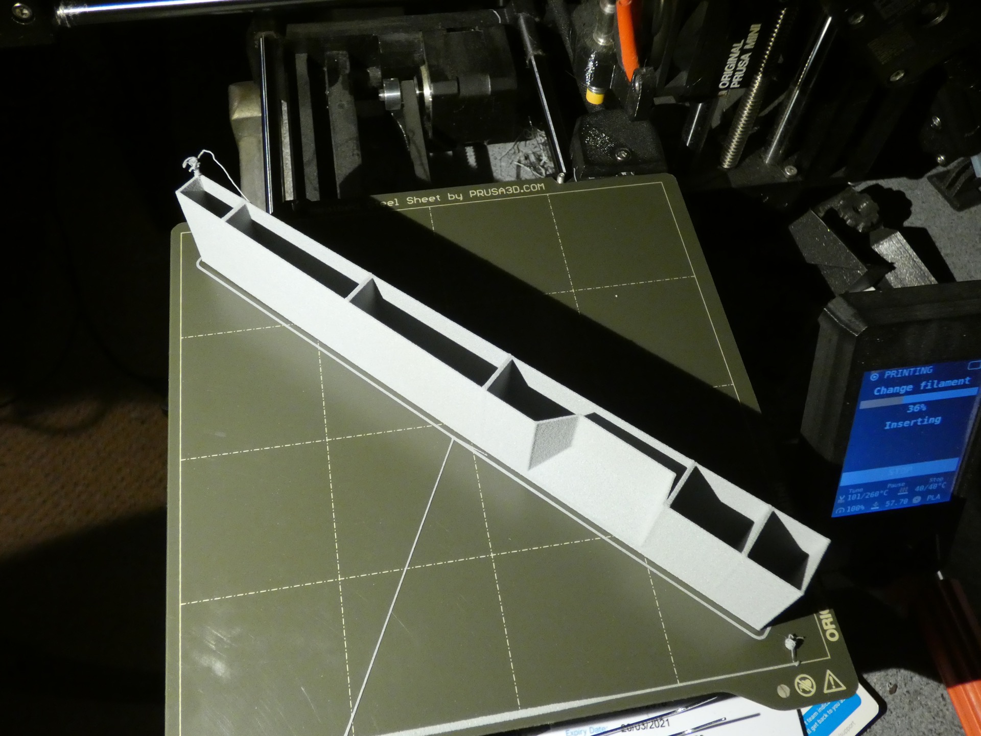
The completed print - the flat trailing edge of course printed open in vase mode - so a cover needed. Otherwise the 220mm long beastie is 13.8g.
If I add ~4g for the aileron that is not bad.
I had thought about using a tape hinge for the aileron but recent chatter was mentioning a 'printed hinge'. I would be interested in hearing more about that.

I find that I can borrow entities from prior FreeCAD models to try out new ideas. For example taking the main wing loft and some of the cut-plane and cut-boxes and trying them in a different order.
Next up - the leading edge - I gradually reduce the complexity and look at both a gyroid infil and a vase infil....
As with the aileron, these very thin boxes start 0.8mm above the base of the wing. I kept them a few mm away from the CT to keep them from fighting in the slicer.
I also tried the idea of setting it on the print bed at a diagonal so I could get 220mm of length - thus I could also incude about 40mm of full cord along with the section for the aileron.
I kept the indentation for the servo on the lower face. Here is the print part-way. So clean inside!
The completed print - the flat trailing edge of course printed open in vase mode - so a cover needed. Otherwise the 220mm long beastie is 13.8g.
If I add ~4g for the aileron that is not bad.
I had thought about using a tape hinge for the aileron but recent chatter was mentioning a 'printed hinge'. I would be interested in hearing more about that.
I find that I can borrow entities from prior FreeCAD models to try out new ideas. For example taking the main wing loft and some of the cut-plane and cut-boxes and trying them in a different order.
Next up - the leading edge - I gradually reduce the complexity and look at both a gyroid infil and a vase infil....
Attachments:
Thanks: Klipkopwildlife
Please Log in or Create an account to join the conversation.
- Quorneng
-
Topic Author
- Offline
- Forum Master
-
Less
More
- Posts: 10058
- Thank you received: 19043
26 Feb 2023 16:21 #30
by Quorneng
Replied by Quorneng on topic Printing with Light Weight PLA
I also decided to print a full 240 mm section to see just how strong a 4% gyroid filled wing was.
Trailing edge section ready for an aileron printed on the spar line diagonally across the bed.

Being a flat bottom Clark Y section the aileron can be printed flat on the bed.

As it has a smaller section it is filled at 5% gyroid.
The printed rear parts of the 240 mm wing. Over 5 hours total print time.

Together they weigh 21.9 g
A side view showing the fit of the aileron.

This would suggest a four section 960 mm span 170 mm chord "plank" wing could be under 100 g and might be strong enough without any reinforcing!
Trailing edge section ready for an aileron printed on the spar line diagonally across the bed.
Being a flat bottom Clark Y section the aileron can be printed flat on the bed.
As it has a smaller section it is filled at 5% gyroid.
The printed rear parts of the 240 mm wing. Over 5 hours total print time.
Together they weigh 21.9 g
A side view showing the fit of the aileron.
This would suggest a four section 960 mm span 170 mm chord "plank" wing could be under 100 g and might be strong enough without any reinforcing!
Attachments:
Thanks: Klipkopwildlife, jon.in.swansea
Please Log in or Create an account to join the conversation.
Time to create page: 0.318 seconds