
- Posts: 10058
- Thank you received: 19043
×
Here's one for the serious builders. Show us your ideas
An EDF Concorde - in Depron.
- Quorneng
-
 Topic Author
- Offline
- Forum Master
-

Less
More
06 Feb 2014 13:24 #106
by Quorneng
Replied by Quorneng on topic An EDF Concorde - in Depron.
Hurray!
Hobby King have at last come good with the Orange 3 axis gyro radio (it was originally ordered last October!) and it works!
A clever little thing.

You can see the 'Delta' (elevons) configuration has been selected on the dip switch so the servos move for both pitch and roll.
However in my Concorde there is an additional elevator servo that only wants to act in pitch so I will have to set the radio back to 'ordinary' to allow the elevator servo to be connected and use a 'downstream' mixer unit for the two elevon servos.
The only other issue is the Aux channel ('flap' on the DX6i) can be used to switch off the gyros from the Tx. The Aux channel has to be set to between 1.7 & 2.1 ms to inhibit the gyros, any other signal activates them. So far I have not been able to get the flap switch to do this.
Hobby King have at last come good with the Orange 3 axis gyro radio (it was originally ordered last October!) and it works!
A clever little thing.
You can see the 'Delta' (elevons) configuration has been selected on the dip switch so the servos move for both pitch and roll.
However in my Concorde there is an additional elevator servo that only wants to act in pitch so I will have to set the radio back to 'ordinary' to allow the elevator servo to be connected and use a 'downstream' mixer unit for the two elevon servos.
The only other issue is the Aux channel ('flap' on the DX6i) can be used to switch off the gyros from the Tx. The Aux channel has to be set to between 1.7 & 2.1 ms to inhibit the gyros, any other signal activates them. So far I have not been able to get the flap switch to do this.
Thanks: Eric, Klipkopwildlife, Sarah-Jane Smith
Please Log in or Create an account to join the conversation.
- Quorneng
-
Topic Author
- Offline
- Forum Master
-
Less
More
- Posts: 10058
- Thank you received: 19043
09 Feb 2014 00:57 #107
by Quorneng
Replied by Quorneng on topic An EDF Concorde - in Depron.
The saga continues.
I have now connected up all the control surfaces.
Just for testing I am using a basic Orange R615 and a conventional set up on the DX6i. This requires a separate mixer unit for the elevon servos but allows a Y lead on the Rx elevator port to drive the dedicated elevator servo.
After a bit of playing around I managed to get all the surfaces to move in the correct way.
This represented a positive step forward so provided the EDFs worked the final positions of the radio and battery could be determined.
But I should have known each step forward is followed promptly by one back!
One the bearings in the RH outboard fan has completed disintegrated! The fan touches the case just rotating it by hand.
This fan has only ever been test run on the Concorde so for no more than 2 or 3 minutes from new.
So I now have one EDF with a good motor and a busted fan and another with a busted motor and a good fan BUT these EDFs are all glued together and cannot be taken apart!!!
I have now connected up all the control surfaces.
Just for testing I am using a basic Orange R615 and a conventional set up on the DX6i. This requires a separate mixer unit for the elevon servos but allows a Y lead on the Rx elevator port to drive the dedicated elevator servo.
After a bit of playing around I managed to get all the surfaces to move in the correct way.
This represented a positive step forward so provided the EDFs worked the final positions of the radio and battery could be determined.
But I should have known each step forward is followed promptly by one back!
One the bearings in the RH outboard fan has completed disintegrated! The fan touches the case just rotating it by hand.
This fan has only ever been test run on the Concorde so for no more than 2 or 3 minutes from new.
So I now have one EDF with a good motor and a busted fan and another with a busted motor and a good fan BUT these EDFs are all glued together and cannot be taken apart!!!
Thanks: Eric, Klipkopwildlife, blue123, Sarah-Jane Smith
Please Log in or Create an account to join the conversation.
- Ex-Member
- Visitor
-

09 Feb 2014 09:22 #108
by Ex-Member
Replied by Ex-Member on topic An EDF Concorde - in Depron.
oh blinking hell Simon, nothing but problems with this one.
i think i will steer clear of edf's they sound like more trouble than they are worth.
i think i will steer clear of edf's they sound like more trouble than they are worth.
Please Log in or Create an account to join the conversation.
- The Beard
-

- Offline
- Forum Master
-
Less
More
- Posts: 9272
- Thank you received: 2167
09 Feb 2014 10:58 #109
by The Beard
Replied by The Beard on topic An EDF Concorde - in Depron.
It all sounds so complex but it seems things that are going wrong shouldnt
Please Log in or Create an account to join the conversation.
- Eric
-

- Offline
- Moderator
-

Less
More
- Posts: 15406
- Thank you received: 14306
09 Feb 2014 17:26 #110
by Eric
if you are calm and collected when all about you are going berserk - you've missed something important!
Replied by Eric on topic An EDF Concorde - in Depron.
Not all edf's are trouble, Tony. I know that the other Tony, and Simon, have had trouble, but my d/f U2 is going strong. The wings are getting a bit tatty, being foam, but everything is working fine - even the dead cheap fitted servos (touches a very large oak tree) have been no bother.
if you are calm and collected when all about you are going berserk - you've missed something important!
Please Log in or Create an account to join the conversation.
- Quorneng
-
Topic Author
- Offline
- Forum Master
-
Less
More
- Posts: 10058
- Thank you received: 19043
09 Feb 2014 19:29 #111
by Quorneng
Replied by Quorneng on topic An EDF Concorde - in Depron.
I fear the problem is the cheap tiny EDFs.
8100kV motors are going to rotate pretty fast even on 7.4V and I suspect this speed coupled with the balance (?) of the motor & fan assembly puts the bearings right on their limit.
Still fitting replacement EDF is not difficult as I've already done one, its just the cost, and there is no guarantee that it or any of the three others will last any longer!
8100kV motors are going to rotate pretty fast even on 7.4V and I suspect this speed coupled with the balance (?) of the motor & fan assembly puts the bearings right on their limit.
Still fitting replacement EDF is not difficult as I've already done one, its just the cost, and there is no guarantee that it or any of the three others will last any longer!
Thanks: Eric, The Beard
Please Log in or Create an account to join the conversation.
- Quorneng
-
Topic Author
- Offline
- Forum Master
-
Less
More
- Posts: 10058
- Thank you received: 19043
21 Feb 2014 23:25 - 21 Feb 2014 23:26 #112
by Quorneng
Replied by Quorneng on topic An EDF Concorde - in Depron.
After a bit of investigative work I have discovered that the bearing had not failed in the conventional sense.
The way the motor is laid out means it can only resist thrust in one direction which is not problem for an EDF.
In the rearward direction the only restraint is by the plastic fan body on the front face of motor.
With this particular unit the fan had been glued on the shaft a bit 'short' so the bell had almost 3mm play fore and aft. So much in fact that it had allowed the front bearing to work right out of its housing hence it felt like it had failed completely!

Having got it apart the question is can I now glue the fan back on securely and this time in its correct position to prevent the front bearing from falling out again!
The way the motor is laid out means it can only resist thrust in one direction which is not problem for an EDF.
In the rearward direction the only restraint is by the plastic fan body on the front face of motor.
With this particular unit the fan had been glued on the shaft a bit 'short' so the bell had almost 3mm play fore and aft. So much in fact that it had allowed the front bearing to work right out of its housing hence it felt like it had failed completely!
Having got it apart the question is can I now glue the fan back on securely and this time in its correct position to prevent the front bearing from falling out again!
Last edit: 21 Feb 2014 23:26 by Quorneng.
Thanks: Klipkopwildlife, Sarah-Jane Smith
Please Log in or Create an account to join the conversation.
- Eric
-
- Offline
- Moderator
-
Less
More
- Posts: 15406
- Thank you received: 14306
21 Feb 2014 23:54 #113
by Eric
if you are calm and collected when all about you are going berserk - you've missed something important!
Replied by Eric on topic An EDF Concorde - in Depron.
If it won't go right down, use a spacer!
if you are calm and collected when all about you are going berserk - you've missed something important!
Please Log in or Create an account to join the conversation.
- Quorneng
-
Topic Author
- Offline
- Forum Master
-
Less
More
- Posts: 10058
- Thank you received: 19043
22 Feb 2014 00:20 - 22 Feb 2014 00:20 #114
by Quorneng
Replied by Quorneng on topic An EDF Concorde - in Depron.
Eric
The fan shaft hole is actually drilled (moulded?) right through so it can be pushed as far as required.
My concern is that in breaking the original glue joint how much damage has been done to the inside of the fan hub. It looks ok but you never know at 30,000 rpm+
The fan shaft hole is actually drilled (moulded?) right through so it can be pushed as far as required.
My concern is that in breaking the original glue joint how much damage has been done to the inside of the fan hub. It looks ok but you never know at 30,000 rpm+
Last edit: 22 Feb 2014 00:20 by Quorneng.
Thanks: The Beard
Please Log in or Create an account to join the conversation.
- Quorneng
-
Topic Author
- Offline
- Forum Master
-
Less
More
- Posts: 10058
- Thank you received: 19043
23 Feb 2014 15:27 - 23 Feb 2014 15:28 #115
by Quorneng
Replied by Quorneng on topic An EDF Concorde - in Depron.
All back together and the servo wiring rearranged saving 1/2oz (13g) in weight.
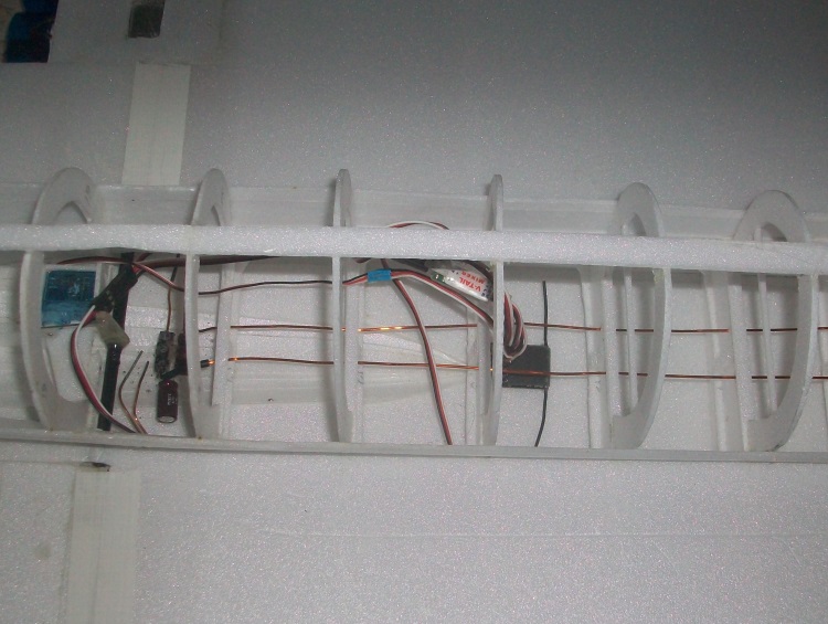
1/2 oz may sound trivial but it is nearly 5% of the all up weight.
Full power tested has revealed what could be a very serious issue.
With all four fans running at anything above about 3/4 power one of the fans starts to slow down (it could be more but it is hard to tell which) whilst the others continue on up to full power.
When either the left or right hand pairs are run up independently full speed (drawing 21A for the pair) is no problem and can be sustained.
I suspect this might be the result of some sort of input harmonic resulting from the long ESC to battery lead as this characteristic was not noticeable during the limited full power testing when the battery was mounted close to the ESCs.
Even if this is not the actual cause of the problem I do have concerns at the long battery lead but to solve it requires a complete change to the electrical layout. This in turn will require major surgery to the wings which at the moment are beautifully smooth single sheets of Depron.
The problem is quite a lot of work is involved, it will be difficult to restore the wing to its current state, there is no guarantee that the revised layout will be any more reliable and the whole concept of 4 tiny EDFs was always more impressive than practical!
Drat and double drat!
I shall have to think about this.
1/2 oz may sound trivial but it is nearly 5% of the all up weight.
Full power tested has revealed what could be a very serious issue.
With all four fans running at anything above about 3/4 power one of the fans starts to slow down (it could be more but it is hard to tell which) whilst the others continue on up to full power.
When either the left or right hand pairs are run up independently full speed (drawing 21A for the pair) is no problem and can be sustained.
I suspect this might be the result of some sort of input harmonic resulting from the long ESC to battery lead as this characteristic was not noticeable during the limited full power testing when the battery was mounted close to the ESCs.
Even if this is not the actual cause of the problem I do have concerns at the long battery lead but to solve it requires a complete change to the electrical layout. This in turn will require major surgery to the wings which at the moment are beautifully smooth single sheets of Depron.
The problem is quite a lot of work is involved, it will be difficult to restore the wing to its current state, there is no guarantee that the revised layout will be any more reliable and the whole concept of 4 tiny EDFs was always more impressive than practical!
Drat and double drat!
I shall have to think about this.
Last edit: 23 Feb 2014 15:28 by Quorneng.
Thanks: Klipkopwildlife, Ex-Member, blue123, Sarah-Jane Smith, old fart
Please Log in or Create an account to join the conversation.
- Eric
-
- Offline
- Moderator
-
Less
More
- Posts: 15406
- Thank you received: 14306
23 Feb 2014 16:15 #116
by Eric
if you are calm and collected when all about you are going berserk - you've missed something important!
Replied by Eric on topic An EDF Concorde - in Depron.
It might be too obvious - but how many amps can the lipo deliver on continuous load - not momentary peak - . From your description of some of the fans slowing down, you might be asking too much of it. A tiny mis-match between the four motors and speedos could see that happening, ie as the load voltage drops, one or more speedos are 'losing the plot'.
Just as a temporary measure, try putting two lipo's in parallel, so you have more amps available.
Just as a temporary measure, try putting two lipo's in parallel, so you have more amps available.
if you are calm and collected when all about you are going berserk - you've missed something important!
Please Log in or Create an account to join the conversation.
- Quorneng
-
Topic Author
- Offline
- Forum Master
-
Less
More
- Posts: 10058
- Thank you received: 19043
23 Feb 2014 23:28 #117
by Quorneng
Replied by Quorneng on topic An EDF Concorde - in Depron.
That was my first thought too but one motor started slowing with the Watt meter only showing 17A which was actually a lower figure than full power (21A) on two.
I am sure you are correct one (or more) of the ESCs was 'loosing it' but it does not appear to be due to voltage sag.
These fans spin pretty fast so my guess is it doesn't take much superimposed 'interference' on the input side to upset the ESCs timing.
Of course if I was doing it properly I should have laid out all the electrics in a 'systems rig' to fully test the complete set up before building anything in, just like they used to when building prototype planes!
My intention, if and when the mood takes me, is to move the ESCs right to the front of the ducts. They will then be close to the CofG rather than 18" behind it. As a result the battery will go further aft (and towards the ESCs) which should reduce the ESC to battery lead length by at least 2/3.
I am sure you are correct one (or more) of the ESCs was 'loosing it' but it does not appear to be due to voltage sag.
These fans spin pretty fast so my guess is it doesn't take much superimposed 'interference' on the input side to upset the ESCs timing.
Of course if I was doing it properly I should have laid out all the electrics in a 'systems rig' to fully test the complete set up before building anything in, just like they used to when building prototype planes!
My intention, if and when the mood takes me, is to move the ESCs right to the front of the ducts. They will then be close to the CofG rather than 18" behind it. As a result the battery will go further aft (and towards the ESCs) which should reduce the ESC to battery lead length by at least 2/3.
Please Log in or Create an account to join the conversation.
- The Beard
-
- Offline
- Forum Master
-
Less
More
- Posts: 9272
- Thank you received: 2167
24 Feb 2014 00:41 - 24 Feb 2014 08:29 #118
by The Beard
Replied by The Beard on topic An EDF Concorde - in Depron.
I had a similar problem on my twinstar with only 2 motors when I changed to brushless.Lots of long wires involved.I had 24 connections.By changing to gold connectors the problem was solved.Ive heard there can be voltage drop if wiring is too long and I think your theory on getting the ESC and batteries closer together is the right one.
Last edit: 24 Feb 2014 08:29 by .
Please Log in or Create an account to join the conversation.
- Quorneng
-
Topic Author
- Offline
- Forum Master
-
Less
More
- Posts: 10058
- Thank you received: 19043
24 Feb 2014 12:54 #119
by Quorneng
Replied by Quorneng on topic An EDF Concorde - in Depron.
Just a bit more thought on this.
I have ordered some more enamelled magnet wire of two different thickness's.
The intention is to keep the same total wire cross section throughout so 3x0.5mm wires from the motor to ESC then 2x0.63mm from the ESC. To avoid making high current connections each ESC will have its own wires running to the battery.
In addition I may also move the elevator servo right forward and use a long (1000mm) lightweight snake. Doing this is actually slightly heavier overall but has a significant impact on the weight distribution creating a nose down shift of 440 gcm. To compensate the 148g battery will have to be moved 3 cm further back. Every little helps!
I have ordered some more enamelled magnet wire of two different thickness's.
The intention is to keep the same total wire cross section throughout so 3x0.5mm wires from the motor to ESC then 2x0.63mm from the ESC. To avoid making high current connections each ESC will have its own wires running to the battery.
In addition I may also move the elevator servo right forward and use a long (1000mm) lightweight snake. Doing this is actually slightly heavier overall but has a significant impact on the weight distribution creating a nose down shift of 440 gcm. To compensate the 148g battery will have to be moved 3 cm further back. Every little helps!
Thanks: Eric, blue123, Sarah-Jane Smith
Please Log in or Create an account to join the conversation.
- Quorneng
-
Topic Author
- Offline
- Forum Master
-
Less
More
- Posts: 10058
- Thank you received: 19043
12 Mar 2014 11:07 #120
by Quorneng
Replied by Quorneng on topic An EDF Concorde - in Depron.
Started the long process of completely reorganising the wiring.
First the ESCs have to be removed and the duct wall made good.
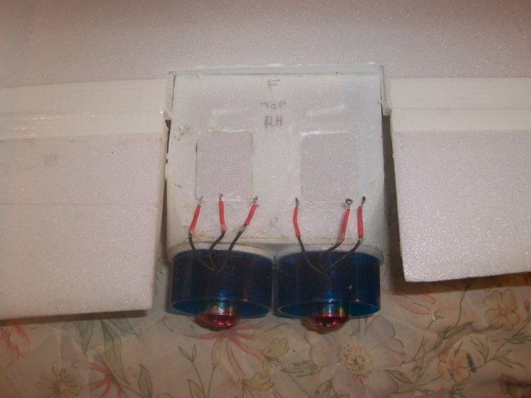
The next problem is to work out how to feed the six motor wires (0.5mm solid copper) through the wing to the ESCs which will be mounted at the front of the ducts. The problem is any cut out in the wing skin must be kept as small as possible (and preferably not cut at all!) as there is no internal reinforcement, the skin carries all the load.
The good part is that the 4 ESCs and their wires weigh 1.8oz and are being moved forward 14" which will allow the battery to be moved back 4.5". Together these moves will at least halve the battery to ESC distance.
First the ESCs have to be removed and the duct wall made good.
The next problem is to work out how to feed the six motor wires (0.5mm solid copper) through the wing to the ESCs which will be mounted at the front of the ducts. The problem is any cut out in the wing skin must be kept as small as possible (and preferably not cut at all!) as there is no internal reinforcement, the skin carries all the load.
The good part is that the 4 ESCs and their wires weigh 1.8oz and are being moved forward 14" which will allow the battery to be moved back 4.5". Together these moves will at least halve the battery to ESC distance.
Thanks: Eric, Klipkopwildlife, blue123, Sarah-Jane Smith, old fart
Please Log in or Create an account to join the conversation.
Time to create page: 0.674 seconds