
- Posts: 757
- Thank you received: 1164
- Forum
- Forum Categories
- General Chat (Including Our Fun Thread, The Cafe)
- Revisiting paper airplanes - like we probably all started out with...
Revisiting paper airplanes - like we probably all started out with...
- jon.in.swansea
-
 Topic Author
- Offline
- Elite Member
-

Less
More
22 Feb 2025 18:43 #1
by jon.in.swansea
Revisiting paper airplanes - like we probably all started out with... was created by jon.in.swansea
Back when I was getting started with foam scratch builds I did a few delta-ish wings. Start was to take a 'power-up' module which was came with paper that you were supposed to fold up and mount it to. Tony watched me do the initial paper version of this because my fingers didn't have to unlearn normal control 'sticks'.
Later I mounted in on some foam. The ailerons were fixed and altitude was just via altering the motor speed and it used differential on the two props. Control was wifi via an app on phone. Needless to say it needed absolute calm to fly. It could fly amazingly slowly and thus could respond nicely to my novice fingers.
 And I later got a 'power-up2' which had greater range and a bit better controls and even a wee camera. Again, calm days only. It was a great park flyer - say up to tree height. Unfortunately when up at 50m at distance I managed to exceed it's control range and with no one to tell it what to do it planted itself in the top of the trees at the end of the field.

There was a period when I was working from flight-test plans. They had a common power-pod with different wing forms. One was a Delta-ish-flying-wing tractor. Used what I remember is called a K-step wing form. It had that characteristic roll wobble and was fairly bullet proof. I did manage to toast it at some point....
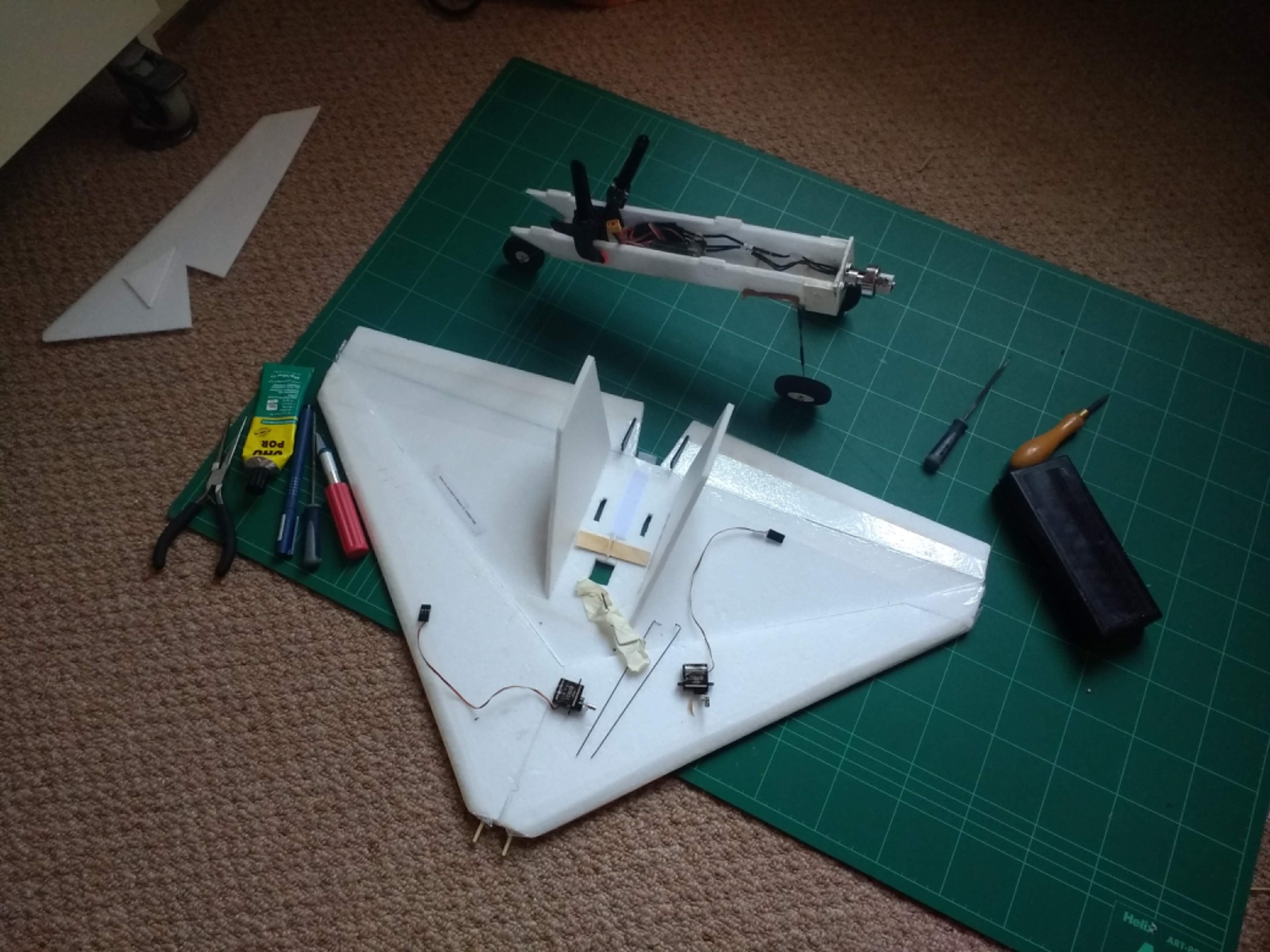
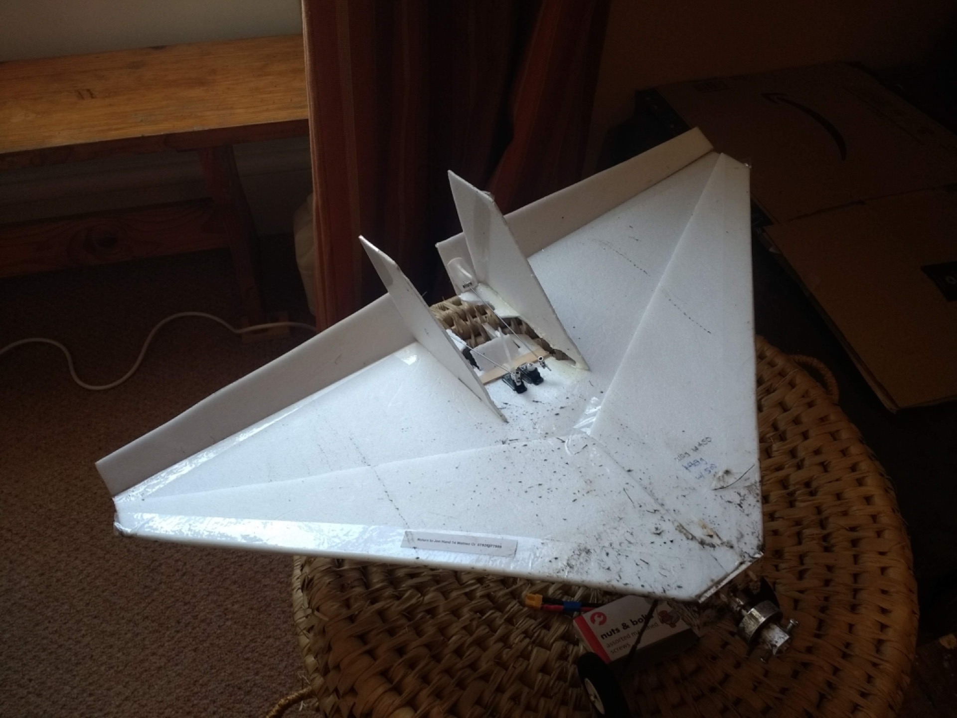
And then I did my own design of a delta-ish flying wing from looking at what others had done. It played more with the steps in the upper surface of the wing. Rather than a flat slab the leading edge was similar to the lead edge of the foam Armin wings I had been making. Bigger and faster but still with that characteristic roll wobble.

So why this 'memory lane' stuff?
Having been playing around with the wings from PlanePrint I ventured back on their site to look up some details and noticed there was something labeled as a 'printed paper plane'.
And indeed it is, down to the mock-folds. I thought this might be fun so I bought the plans. Also it would get me used to the CA glue of LW-PLA with tabs which PlanePrint like.

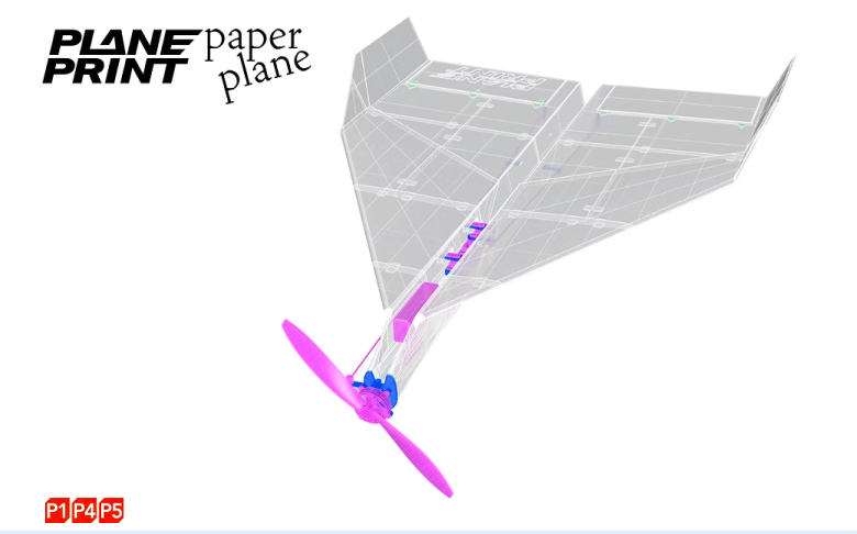
The intreguing bit is that yes, one might gently use the control surfaces to turn but rather than differential props of the power-up ancient variants this model has the prop mounted on a gimbel and can rotate to become essentially a tractor rudder. Just crazy enough.

So here is the view from below.... I think that before I fly it I am going to design a PLA base skid to glue all along the 'keel'. I can't see that LW-PLA lasting for many belly landings and the skid can act to reinforce the joins.

And view from above. There are some minor gaps which I need to fill in. Holding the join tightly while reaching for 'kicker' really needs 3 sets of fingers. I think 1mm x 5mm x 200mm strips could be glued to the top would help take the stresses fro some of those joins. Perhaps some coloured packing tape to add some directional colour (grey plane on grey sky is just asking for trouble).

It has 500mm span, 800 length, printed only bits are around 220g. Recommends a 22x4 1000kv motor, 800mahr battery 8x4 prop. Should be able to put that together.
Later I mounted in on some foam. The ailerons were fixed and altitude was just via altering the motor speed and it used differential on the two props. Control was wifi via an app on phone. Needless to say it needed absolute calm to fly. It could fly amazingly slowly and thus could respond nicely to my novice fingers.
There was a period when I was working from flight-test plans. They had a common power-pod with different wing forms. One was a Delta-ish-flying-wing tractor. Used what I remember is called a K-step wing form. It had that characteristic roll wobble and was fairly bullet proof. I did manage to toast it at some point....
And then I did my own design of a delta-ish flying wing from looking at what others had done. It played more with the steps in the upper surface of the wing. Rather than a flat slab the leading edge was similar to the lead edge of the foam Armin wings I had been making. Bigger and faster but still with that characteristic roll wobble.
So why this 'memory lane' stuff?
Having been playing around with the wings from PlanePrint I ventured back on their site to look up some details and noticed there was something labeled as a 'printed paper plane'.
And indeed it is, down to the mock-folds. I thought this might be fun so I bought the plans. Also it would get me used to the CA glue of LW-PLA with tabs which PlanePrint like.
The intreguing bit is that yes, one might gently use the control surfaces to turn but rather than differential props of the power-up ancient variants this model has the prop mounted on a gimbel and can rotate to become essentially a tractor rudder. Just crazy enough.
So here is the view from below.... I think that before I fly it I am going to design a PLA base skid to glue all along the 'keel'. I can't see that LW-PLA lasting for many belly landings and the skid can act to reinforce the joins.
And view from above. There are some minor gaps which I need to fill in. Holding the join tightly while reaching for 'kicker' really needs 3 sets of fingers. I think 1mm x 5mm x 200mm strips could be glued to the top would help take the stresses fro some of those joins. Perhaps some coloured packing tape to add some directional colour (grey plane on grey sky is just asking for trouble).
It has 500mm span, 800 length, printed only bits are around 220g. Recommends a 22x4 1000kv motor, 800mahr battery 8x4 prop. Should be able to put that together.
Attachments:
Thanks: Eric, Klipkopwildlife, Flytilbroke, Quorneng
Please Log in or Create an account to join the conversation.
- Quorneng
-

- Offline
- Forum Master
-

Less
More
- Posts: 10058
- Thank you received: 19043
22 Feb 2025 22:11 #2
by Quorneng
Replied by Quorneng on topic Revisiting paper airplanes - like we probably all started out with...
An interesting concept.
A true paper plane is made of paper so has to have flat surfaces. Paper is cheap so the plane can be disposable.
LW-PLA on the other hand is not so cheap raising the question are basic flat surfaces appropriate.
My own view is it would probably fly and resit knocks better if the basic wing construction had some depth to it.
Now an RC plane made only of paper would be a challenge.

A true paper plane is made of paper so has to have flat surfaces. Paper is cheap so the plane can be disposable.
LW-PLA on the other hand is not so cheap raising the question are basic flat surfaces appropriate.
My own view is it would probably fly and resit knocks better if the basic wing construction had some depth to it.
Now an RC plane made only of paper would be a challenge.
Thanks: Klipkopwildlife, jon.in.swansea
Please Log in or Create an account to join the conversation.
- Klipkopwildlife
-

- Offline
- Administrator
-

- I'm supposed to be retired!
03 Mar 2025 13:30 - 03 Mar 2025 13:31 #3
by Klipkopwildlife
Do it now, you may never get another chance
Replied by Klipkopwildlife on topic Revisiting paper airplanes - like we probably all started out with...
Ooh, I like that Jon, I wouldn't bother making a skid, at 18gm/dm it's going to fly very slowly and because of the delta characteristics the landing speed will be just about zero, ask Simon!
Remember the big secret in aeromodelling is to add lightness!
The vector prop is interesting, remember you'll only be able to turn quickly with throttle on. I would be tempted to fit a folding prop if at all possible.
I'm looking at buying one for myself.
Remember the big secret in aeromodelling is to add lightness!
The vector prop is interesting, remember you'll only be able to turn quickly with throttle on. I would be tempted to fit a folding prop if at all possible.
I'm looking at buying one for myself.
Do it now, you may never get another chance
Last edit: 03 Mar 2025 13:31 by Klipkopwildlife.
Thanks: jon.in.swansea
Please Log in or Create an account to join the conversation.
- Quorneng
-
- Offline
- Forum Master
-
Less
More
- Posts: 10058
- Thank you received: 19043
03 Mar 2025 15:01 - 03 Mar 2025 15:07 #4
by Quorneng
Replied by Quorneng on topic Revisiting paper airplanes - like we probably all started out with...
From my experience of low wing loading delta turning is not a problem using just the elevons. If anything it is the opposite.
The control surfaces are very large and a delta is very sensitive in roll and because the control surfaces are relatively close to the CG it is also pitch sensitive.
It will hardly turn at all just applying roll but add just a bit of "up" and it will turn fast. The problem is applying the right amount of roll and "up" and then regulating it to maintain the desired rate of turn. True "Bank and yank".
My HP115 which is about the nearest hing to a paper dart. As you can see it is a) quite controllable and b) pretty maneuverable using just the elevons..
I wouldn't worry too much about underside wear at least when landing on grass.
.
The control surfaces are very large and a delta is very sensitive in roll and because the control surfaces are relatively close to the CG it is also pitch sensitive.
It will hardly turn at all just applying roll but add just a bit of "up" and it will turn fast. The problem is applying the right amount of roll and "up" and then regulating it to maintain the desired rate of turn. True "Bank and yank".
My HP115 which is about the nearest hing to a paper dart. As you can see it is a) quite controllable and b) pretty maneuverable using just the elevons..
I wouldn't worry too much about underside wear at least when landing on grass.
.
Last edit: 03 Mar 2025 15:07 by Quorneng.
Thanks: Klipkopwildlife, THE BLACKBIRD, jon.in.swansea
Please Log in or Create an account to join the conversation.
- jon.in.swansea
-
Topic Author
- Offline
- Elite Member
-
Less
More
- Posts: 757
- Thank you received: 1164
03 Mar 2025 17:50 #5
by jon.in.swansea
Replied by jon.in.swansea on topic Revisiting paper airplanes - like we probably all started out with...
As my fingers tend to default to using ailerons rather than rudder I probably will not touch the vector in early flights. The nose shape is such that it will probably not get on well with a folding prop. I certainly will be using a prop-saver!
My main thing with a skid is that the motor is at the base and is just asking to suck up water, mud, sand or who know what on even the best landing. If I can design a skid that can elevate it even a bit then I won't have to return to base to endlessly return to base to for cleaning.
My main thing with a skid is that the motor is at the base and is just asking to suck up water, mud, sand or who know what on even the best landing. If I can design a skid that can elevate it even a bit then I won't have to return to base to endlessly return to base to for cleaning.
Thanks: Klipkopwildlife, Quorneng
Please Log in or Create an account to join the conversation.
- jon.in.swansea
-
Topic Author
- Offline
- Elite Member
-
Less
More
- Posts: 757
- Thank you received: 1164
03 Mar 2025 17:55 #6
by jon.in.swansea
Replied by jon.in.swansea on topic Revisiting paper airplanes - like we probably all started out with...
That video was very instructive. I will be reviewing that quite often before I head out....
Thanks: Klipkopwildlife, Flytilbroke, Quorneng
Please Log in or Create an account to join the conversation.
- Quorneng
-
- Offline
- Forum Master
-
Less
More
- Posts: 10058
- Thank you received: 19043
03 Mar 2025 20:26 #7
by Quorneng
Replied by Quorneng on topic Revisiting paper airplanes - like we probably all started out with...
This is the other video of the HP115 doing a true "flop" landing. It takes a bit of coordination. I certainly can't guarantee to do it every time!
Thanks: Klipkopwildlife, jon.in.swansea
Please Log in or Create an account to join the conversation.
- jon.in.swansea
-
Topic Author
- Offline
- Elite Member
-
Less
More
- Posts: 757
- Thank you received: 1164
04 Mar 2025 09:24 #8
by jon.in.swansea
Replied by jon.in.swansea on topic Revisiting paper airplanes - like we probably all started out with...
Wow your fingers really knew how to make it dance that time!
Thanks: Klipkopwildlife, Quorneng
Please Log in or Create an account to join the conversation.
- jon.in.swansea
-
Topic Author
- Offline
- Elite Member
-
Less
More
- Posts: 757
- Thank you received: 1164
22 Mar 2025 09:24 #9
by jon.in.swansea
Replied by jon.in.swansea on topic Revisiting paper airplanes - like we probably all started out with...
It got warm enough in the man-cave to return to the printed paper airplane. Looking back over the print it became clear that there were a couple of weak points....
First, I had a slightly paranoid opinion about the CA glue in the larger pieces and how stresses in landing might pop those. So I decided to print some PETG 6mm x 0.8mm strips to bridge over some of the joins.
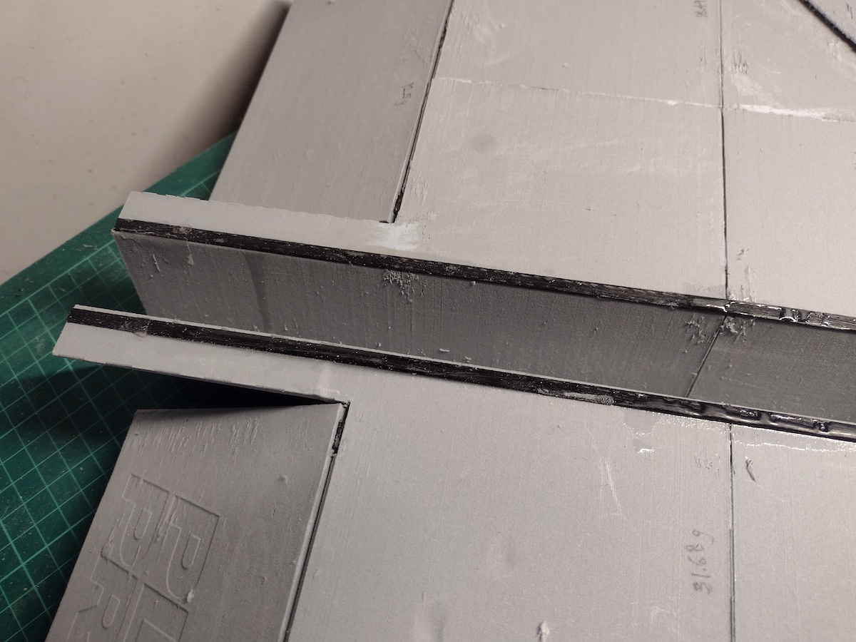
And then I was thinking of adding some abrasion resistance at the edge of the delta. The next was the area adjacent to the elevons - even initial handling showed limited strength and ease of cracking and also at the trailing edge it looked all to easy for the wing to bind with the elevon so I added a PETG strip to hopefully limit that binding.

The next is a niggle about the design. When loose-fitting the servos the slots they provided clearly did not allow for full travel so I had to get out the file to ensure that it did not bind and rip the support for the servo. Also seen is another of the reinforcing strips - that might cause me grief because of clearance for attaching the linkage...

First, I had a slightly paranoid opinion about the CA glue in the larger pieces and how stresses in landing might pop those. So I decided to print some PETG 6mm x 0.8mm strips to bridge over some of the joins.
And then I was thinking of adding some abrasion resistance at the edge of the delta. The next was the area adjacent to the elevons - even initial handling showed limited strength and ease of cracking and also at the trailing edge it looked all to easy for the wing to bind with the elevon so I added a PETG strip to hopefully limit that binding.
The next is a niggle about the design. When loose-fitting the servos the slots they provided clearly did not allow for full travel so I had to get out the file to ensure that it did not bind and rip the support for the servo. Also seen is another of the reinforcing strips - that might cause me grief because of clearance for attaching the linkage...
Attachments:
Thanks: Klipkopwildlife, Quorneng
Please Log in or Create an account to join the conversation.
- Klipkopwildlife
-
- Offline
- Administrator
-
- I'm supposed to be retired!
22 Mar 2025 13:05 #10
by Klipkopwildlife
Do it now, you may never get another chance
Replied by Klipkopwildlife on topic Revisiting paper airplanes - like we probably all started out with...
I didn't bother to open the slots, I've just limited the maximum travel of the servos. With your radio it should be easier to add some aileron/rudder coupling, 15% should be enough to start.
Do it now, you may never get another chance
Thanks: jon.in.swansea
Please Log in or Create an account to join the conversation.
- jon.in.swansea
-
Topic Author
- Offline
- Elite Member
-
Less
More
- Posts: 757
- Thank you received: 1164
25 Mar 2025 10:52 #11
by jon.in.swansea
Replied by jon.in.swansea on topic Revisiting paper airplanes - like we probably all started out with...
After the curious incident of the initial servo choice being a non-starter (in another thread that seemed to eat up quite a bit of Monday)... I went about replacing them with 5g servos that worked with the Futaba. And of course the servo arms are different and don't fit the printed servo are extenders provided by PlanePrint.
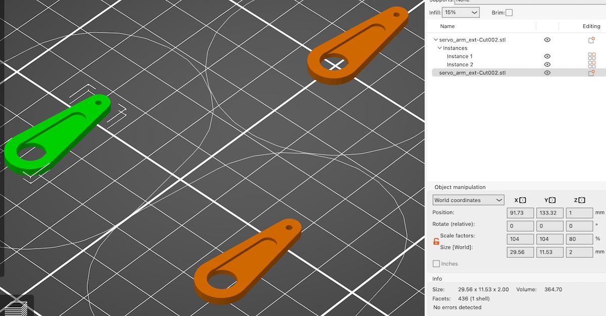
The supplied servo are extenders are an accident waiting to happen. Getting Nylon arms attached to PLA or PETG is bound to fail as almost nothing sticks to Nylon. I remembered an alternative design I got from somewhere, even got a photo of it and a printed example. So, got out the calipers and sketched out a design that had a better hope of lasting more than one flight. The trick is to wrap the extension over the Nylon so that the torque is less likely to break the join.
Below (from lower left to upper right) The original extender CA'd to the 9g Nylon arm. It was coming loose just getting it off the 9g servo. Next up is the example of the design I wanted to copy but didn't have the file for. Next up are a couple of the newly printed extenders to match the 5g servo arm and lastly the not-yet-glued rig.

Calibration involved printing out an initial extension plus one that was 4% bigger. Test fitted and found the bigger on worked best but was thicker than needed so I went back and
tweaked the Printer slicer to thin down the Z axis.
So glad that I had not glued the servos in place. Other niggle with the PlanePrint - their manual suggested that one could put the reciever below the servos - no way there was space, hardly enough for the servo wiring. Don't like the idea of receiver that close to the servos either. Thankfully there is space just aft of the servos which provides easier access for wiring.
Fun half hour project on FreeCAD to get this setup. Helped me to sort of out a workflow for setting up solids representing the primary elements from measurements and then sketching over it to make the extension arm and the cutout for the Nylon to fit within. Now that I have the basics down I can then tweak it to work with other arms and extension lengths. If any of you have a need for that I am willing to give it a try....
The supplied servo are extenders are an accident waiting to happen. Getting Nylon arms attached to PLA or PETG is bound to fail as almost nothing sticks to Nylon. I remembered an alternative design I got from somewhere, even got a photo of it and a printed example. So, got out the calipers and sketched out a design that had a better hope of lasting more than one flight. The trick is to wrap the extension over the Nylon so that the torque is less likely to break the join.
Below (from lower left to upper right) The original extender CA'd to the 9g Nylon arm. It was coming loose just getting it off the 9g servo. Next up is the example of the design I wanted to copy but didn't have the file for. Next up are a couple of the newly printed extenders to match the 5g servo arm and lastly the not-yet-glued rig.
Calibration involved printing out an initial extension plus one that was 4% bigger. Test fitted and found the bigger on worked best but was thicker than needed so I went back and
tweaked the Printer slicer to thin down the Z axis.
So glad that I had not glued the servos in place. Other niggle with the PlanePrint - their manual suggested that one could put the reciever below the servos - no way there was space, hardly enough for the servo wiring. Don't like the idea of receiver that close to the servos either. Thankfully there is space just aft of the servos which provides easier access for wiring.
Fun half hour project on FreeCAD to get this setup. Helped me to sort of out a workflow for setting up solids representing the primary elements from measurements and then sketching over it to make the extension arm and the cutout for the Nylon to fit within. Now that I have the basics down I can then tweak it to work with other arms and extension lengths. If any of you have a need for that I am willing to give it a try....
Attachments:
Thanks: Klipkopwildlife
Please Log in or Create an account to join the conversation.
- Eric
-

- Offline
- Moderator
-

Less
More
- Posts: 15406
- Thank you received: 14305
25 Mar 2025 10:57 #12
by Eric
if you are calm and collected when all about you are going berserk - you've missed something important!
Replied by Eric on topic Revisiting paper airplanes - like we probably all started out with...
A high-tech solution to a simple problem - I'd have just put a couple of tiny screws through the existing holes in the servo arm, and into the extender!

if you are calm and collected when all about you are going berserk - you've missed something important!
Thanks: Klipkopwildlife, jon.in.swansea
Please Log in or Create an account to join the conversation.
- Quorneng
-
- Offline
- Forum Master
-
Less
More
- Posts: 10058
- Thank you received: 19043
25 Mar 2025 11:41 #13
by Quorneng
Replied by Quorneng on topic Revisiting paper airplanes - like we probably all started out with...
Now if you were really confident with Free Cad you could print a new servo arm , including the spline!
Always a bit nervous about glue on nylon, even CA If it fails extended comes off = no control!.
Always a bit nervous about glue on nylon, even CA If it fails extended comes off = no control!.
Thanks: Eric, Klipkopwildlife, jon.in.swansea
Please Log in or Create an account to join the conversation.
- jon.in.swansea
-
Topic Author
- Offline
- Elite Member
-
Less
More
- Posts: 757
- Thank you received: 1164
25 Mar 2025 14:19 #14
by jon.in.swansea
Replied by jon.in.swansea on topic Revisiting paper airplanes - like we probably all started out with...
The thing that keeps me away from printing the arm is the very fine ridges on the servo. Each mfg seems to go into a different density and without a match there is less grab. The scale of those ridges is about a magnitude less than most 3D printers can manage.
Thanks: Klipkopwildlife
Please Log in or Create an account to join the conversation.
- Eric
-
- Offline
- Moderator
-
Less
More
- Posts: 15406
- Thank you received: 14305
25 Mar 2025 15:16 - 25 Mar 2025 15:17 #15
by Eric
if you are calm and collected when all about you are going berserk - you've missed something important!
Replied by Eric on topic Revisiting paper airplanes - like we probably all started out with...
The 'fine ridges' are the spline!

Another thing - lengthening the servo arm means that the control surface needs it's control horn lengthening by the same amount or the movement will be greatly enlarged.
AND
by lengthening the arm, you are reducing the amount of force the servo can generate - it's all about leverage and fulcrums. (the fulcrum, of course, is the servo drive spline!)
Another thing - lengthening the servo arm means that the control surface needs it's control horn lengthening by the same amount or the movement will be greatly enlarged.
AND
by lengthening the arm, you are reducing the amount of force the servo can generate - it's all about leverage and fulcrums. (the fulcrum, of course, is the servo drive spline!)
if you are calm and collected when all about you are going berserk - you've missed something important!
Last edit: 25 Mar 2025 15:17 by Eric. Reason: typo
Thanks: Klipkopwildlife, THE BLACKBIRD, jon.in.swansea
Please Log in or Create an account to join the conversation.
- Forum
- Forum Categories
- General Chat (Including Our Fun Thread, The Cafe)
- Revisiting paper airplanes - like we probably all started out with...
Time to create page: 1.168 seconds