
- Posts: 9436
- Thank you received: 19043
A Depron Airbus A350 - 1000 for 76 mm EDFs
- Quorneng
-
 Topic Author
- Offline
- Forum Master
-

Less
More
01 Nov 2017 00:49 - 01 Nov 2017 00:53 #1
by Quorneng
A Depron Airbus A350 - 1000 for 76 mm EDFs was created by Quorneng
A new thread as it is definitely not going to use 50 mm fans, indeed it is not really going to use 'fans' at all but ducted props!
Although a small diameter ducted prop is inefficient it is significantly more efficient than a true EDF so it can use lighter motors and batteries. the down side it need a relatively bigger duct but the Trent on the A350 gives that even at true scale.
The concept worked well on my first two Depron electric 'jets'.
Well that.s the plan.
.
So to proceed the 'test' bit of fuselage has been extended forward to the point where it starts to reduce in diameter for the cockpit & nose section.

Next it will be extended backwards to the start of the tapered tail section.
The 'set' of formers have been 3D printed for the tapered section of the rear fuselage.
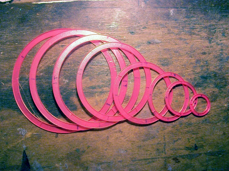
The tapered rear fuselage is a rather complex shape so will be a bit of a nightmare to plank. :ohmy:
Although a small diameter ducted prop is inefficient it is significantly more efficient than a true EDF so it can use lighter motors and batteries. the down side it need a relatively bigger duct but the Trent on the A350 gives that even at true scale.
The concept worked well on my first two Depron electric 'jets'.
Well that.s the plan.
.
So to proceed the 'test' bit of fuselage has been extended forward to the point where it starts to reduce in diameter for the cockpit & nose section.
Next it will be extended backwards to the start of the tapered tail section.
The 'set' of formers have been 3D printed for the tapered section of the rear fuselage.
The tapered rear fuselage is a rather complex shape so will be a bit of a nightmare to plank. :ohmy:
Last edit: 01 Nov 2017 00:53 by Quorneng.
Thanks: Klipkopwildlife, Flytilbroke, THE BLACKBIRD, Ralpharr2001, boz, Squirrelnet
Please Log in or Create an account to join the conversation.
- boz
-

- Offline
- Platinum Member
-

Less
More
- Posts: 1176
- Thank you received: 1420
01 Nov 2017 09:36 #2
by boz
Replied by boz on topic A Depron Airbus A350 - 1000 for 76 mm EDFs
Q, you love a challenge, and I'm pleased the thread is going ahead, following with great interest.
Please Log in or Create an account to join the conversation.
- Quorneng
-
Topic Author
- Offline
- Forum Master
-
Less
More
- Posts: 9436
- Thank you received: 19043
02 Nov 2017 12:06 - 02 Nov 2017 12:07 #3
by Quorneng
Replied by Quorneng on topic A Depron Airbus A350 - 1000 for 76 mm EDFs
The nose section.
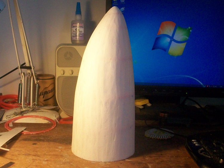
Built the same way as the others but with every plank having to be shaped to fit it is rather more tedious to do.
On the full size only the front cockpit windows are flat so the line of the nose is hardly effected. I have cheated a bit and made the nose line truly smooth but then my cockpit windows are going to be painted on in any case!
On completion the base former of the nose is carefully cut free.
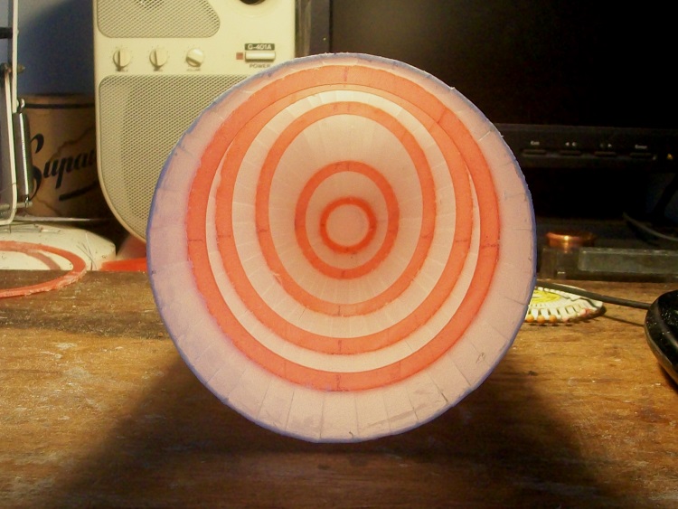
So the skin can be sanded to ensure the nose fits 'true and square' on the fuselage. With such a relatively long fuselage any 'banana' shape would have a serious aerodynamic effect!
To give some strength to what would otherwise be a butt joint a 2x2 mm Depron flange is added to the front of the fuselage former.
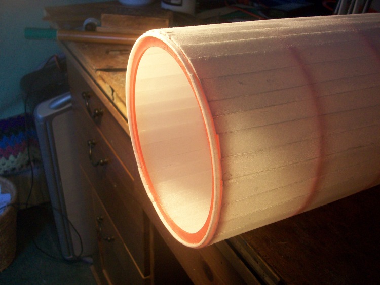
If my CofG guesses are right the fuselage will end up completely empty with only the elevator servo wire running through it as each elevator servos will be in its tail plane. The rudder will be fixed. Everything else will be in the one piece wing.
One advantage of such a long fuselage it only takes a modest nose or tail weight to make a 'useful' adjustment to the CodG.
.
Built the same way as the others but with every plank having to be shaped to fit it is rather more tedious to do.
On the full size only the front cockpit windows are flat so the line of the nose is hardly effected. I have cheated a bit and made the nose line truly smooth but then my cockpit windows are going to be painted on in any case!
On completion the base former of the nose is carefully cut free.
So the skin can be sanded to ensure the nose fits 'true and square' on the fuselage. With such a relatively long fuselage any 'banana' shape would have a serious aerodynamic effect!
To give some strength to what would otherwise be a butt joint a 2x2 mm Depron flange is added to the front of the fuselage former.
If my CofG guesses are right the fuselage will end up completely empty with only the elevator servo wire running through it as each elevator servos will be in its tail plane. The rudder will be fixed. Everything else will be in the one piece wing.
One advantage of such a long fuselage it only takes a modest nose or tail weight to make a 'useful' adjustment to the CodG.
.
Last edit: 02 Nov 2017 12:07 by Quorneng.
Thanks: Klipkopwildlife, THE BLACKBIRD, boz, Squirrelnet
Please Log in or Create an account to join the conversation.
- Quorneng
-
Topic Author
- Offline
- Forum Master
-
Less
More
- Posts: 9436
- Thank you received: 19043
03 Nov 2017 10:51 #4
by Quorneng
Replied by Quorneng on topic A Depron Airbus A350 - 1000 for 76 mm EDFs
The nose &mid section of the fuselage extended rearwards ready for the tail section to be added.

An interesting view inside towards the nose.
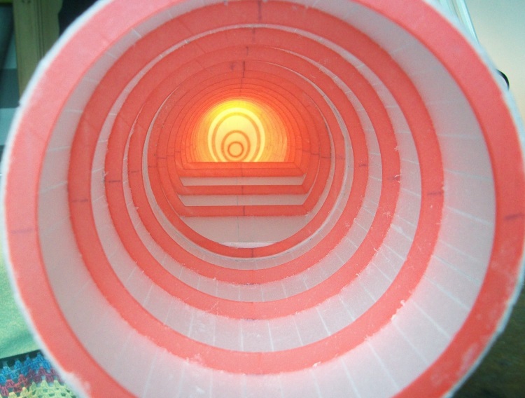
More for the record than anything but nevertheless useful if it ever needs major repair!
.
An interesting view inside towards the nose.
More for the record than anything but nevertheless useful if it ever needs major repair!
.
Thanks: Klipkopwildlife, THE BLACKBIRD, boz
Please Log in or Create an account to join the conversation.
- Quorneng
-
Topic Author
- Offline
- Forum Master
-
Less
More
- Posts: 9436
- Thank you received: 19043
03 Nov 2017 18:07 #5
by Quorneng
Replied by Quorneng on topic A Depron Airbus A350 - 1000 for 76 mm EDFs
Whilst trying to enthusiasm to actually build the tail section I started thinking about whether it was possible to use the same techniques I used for the formers to make the wing ribs.
The A350 will use a symmetrical section something like this.

This has been generated from 4 segments of ellipse so although not a true aerofoil section it is plenty good enough at the size I am using.
Being mathematically generated it can be any thickness, currently at 12%. It has a flat nose to accommodate a solid leading edge.
The wing will use a fully stressed skin structure where the spar flanges are built into the Depron skin.
The size of each rib is set by using the printing scale factor from the initial design of rib.
The 80 mm chord rib (the size close to the wing tip) and a double size version.
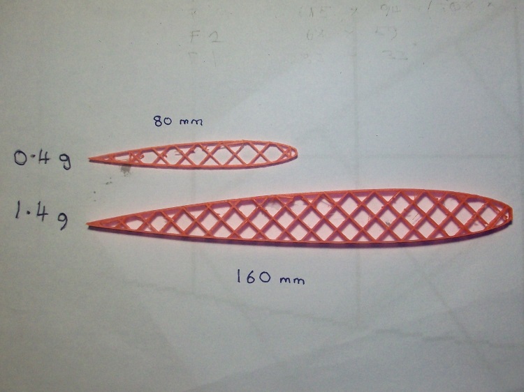
Light and plenty stiff enough. So far so good.
Just out of interest as the ribs are mathematically generated it is no problem to generate a semi symmetrical section by altering the centre points of the ellipses of the lower surface.
The A350 will use a symmetrical section something like this.
This has been generated from 4 segments of ellipse so although not a true aerofoil section it is plenty good enough at the size I am using.
Being mathematically generated it can be any thickness, currently at 12%. It has a flat nose to accommodate a solid leading edge.
The wing will use a fully stressed skin structure where the spar flanges are built into the Depron skin.
The size of each rib is set by using the printing scale factor from the initial design of rib.
The 80 mm chord rib (the size close to the wing tip) and a double size version.
Light and plenty stiff enough. So far so good.
Just out of interest as the ribs are mathematically generated it is no problem to generate a semi symmetrical section by altering the centre points of the ellipses of the lower surface.
Thanks: Klipkopwildlife, boz, Squirrelnet
Please Log in or Create an account to join the conversation.
- Quorneng
-
Topic Author
- Offline
- Forum Master
-
Less
More
- Posts: 9436
- Thank you received: 19043
04 Nov 2017 21:29 #6
by Quorneng
Replied by Quorneng on topic A Depron Airbus A350 - 1000 for 76 mm EDFs
The fuselage tail section being planked.
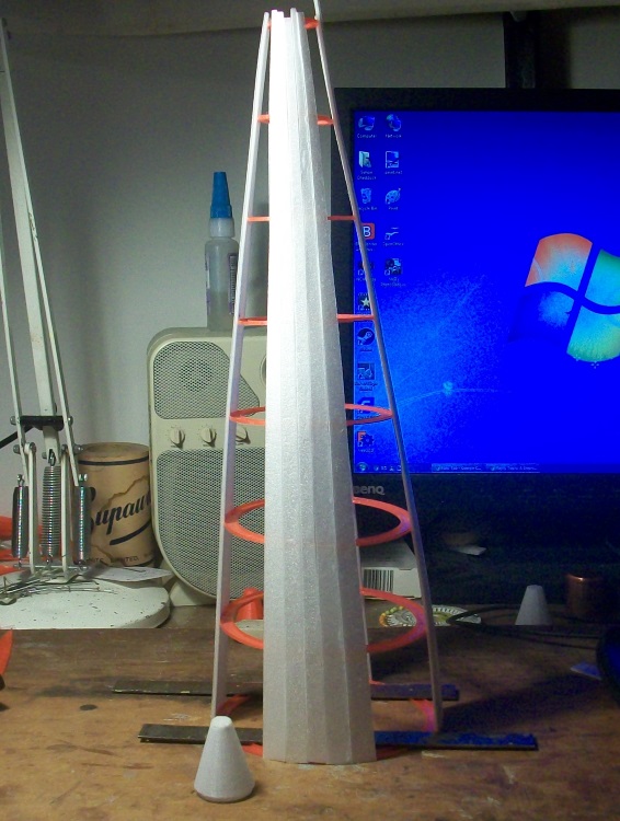
It is now just about rigid enough to lifted and the planking completed 'in the hand'
The printed white 'cone' in the foreground is the APU exhaust which goes on the very end.
It is now just about rigid enough to lifted and the planking completed 'in the hand'
The printed white 'cone' in the foreground is the APU exhaust which goes on the very end.
Thanks: Klipkopwildlife, boz
Please Log in or Create an account to join the conversation.
- Ex-Member
- User
-

Less
More
- Thank you received: 0
04 Nov 2017 21:36 #7
by Ex-Member
Replied by Ex-Member on topic A Depron Airbus A350 - 1000 for 76 mm EDFs
wonderful young sir, but how to you keep it square as you go up?
Tony B
Tony B
Please Log in or Create an account to join the conversation.
- Quorneng
-
Topic Author
- Offline
- Forum Master
-
Less
More
- Posts: 9436
- Thank you received: 19043
04 Nov 2017 23:00 #8
by Quorneng
Replied by Quorneng on topic A Depron Airbus A350 - 1000 for 76 mm EDFs
Tony
A bit of geometry and a lot of eyeball!
Each former has the top,bottom left and right extremes marked on them.
These are then the positions of the first 4 planks. Before the glue sets rigid a tiny plumb bob is suspended from the centre of the top former and the bob's position checked against the base former - in the centre and 40 mm from the top - and with a bit of gentle 'adjustment' it was.
With small thin 2 mm Depron planks glued on alternate sides the stresses required to bend them to the required shape is so low that each new plank creates very little if any additional distortion.
With this type of build it is best not to over think what could go wrong but just do it!
Thanks: Klipkopwildlife, Ex-Member, boz
Please Log in or Create an account to join the conversation.
- Quorneng
-
Topic Author
- Offline
- Forum Master
-
Less
More
- Posts: 9436
- Thank you received: 19043
05 Nov 2017 22:36 - 05 Nov 2017 22:37 #9
by Quorneng
Replied by Quorneng on topic A Depron Airbus A350 - 1000 for 76 mm EDFs
All the fuselage sections joined.

It is 61.5" (1560 mm) long and at 96 g is just within my guesstimated target of 100 g.
Next is to start thinking about the wing although I really need the nacelles with their motors and 'props' before actually building anything.
It is 61.5" (1560 mm) long and at 96 g is just within my guesstimated target of 100 g.
Next is to start thinking about the wing although I really need the nacelles with their motors and 'props' before actually building anything.
Last edit: 05 Nov 2017 22:37 by Quorneng.
Thanks: Klipkopwildlife, boz, Squirrelnet
Please Log in or Create an account to join the conversation.
- Quorneng
-
Topic Author
- Offline
- Forum Master
-
Less
More
- Posts: 9436
- Thank you received: 19043
06 Nov 2017 16:36 - 06 Nov 2017 16:37 #10
by Quorneng
Replied by Quorneng on topic A Depron Airbus A350 - 1000 for 76 mm EDFs
Printed out the wing plan to match the fuselage to get an idea of just how big, or not, it would be.

66" (1680 mm) Span but like all modern airliners it extremely tapered. 14" (355 mm) root chord but only 2.5" (60 mm) at the point where it begins to 'curl up' 90 degrees which is 2" (50 mm) from the actual wing tip. That is a 6:1 taper! I suspect that last little bit of this wing won't do much at my flying speed, apart from create drag!
Despite its extreme taper the full wing has a reasonable area of about 290 sq in, say 2 sq ft.
Now whether the whole plane will come in at or below my target 24 oz is too early to say.
Last edit: 06 Nov 2017 16:37 by Quorneng.
Thanks: Klipkopwildlife, Ex-Member, Ralpharr2001, boz, Squirrelnet
Please Log in or Create an account to join the conversation.
- boz
-
- Offline
- Platinum Member
-
Less
More
- Posts: 1176
- Thank you received: 1420
06 Nov 2017 19:32 #11
by boz
Replied by boz on topic A Depron Airbus A350 - 1000 for 76 mm EDFs
Very informative, very nice work so far, 
Please Log in or Create an account to join the conversation.
- Quorneng
-
Topic Author
- Offline
- Forum Master
-
Less
More
- Posts: 9436
- Thank you received: 19043
07 Nov 2017 19:06 #12
by Quorneng
Replied by Quorneng on topic A Depron Airbus A350 - 1000 for 76 mm EDFs
Designed and printed a nacelle motor mount.

When suspended from the pylon it is intended to be strong enough to carry the motor and 3" prop. It weighs 6 g.
Non load bearing printed inlet and exhaust ducts will be added to this and the whole covered with 2 mm Depron to give the outline of the Trent nacelle.
The big advantage of being a CAD design is that virtually any of its dimensions can be easily changed. It has very thin walls which makes it light so it does not use that much plastic but it takes nearly an hour to print. It pays to double check everything before pressing 'go'.
Thanks: Eric, Klipkopwildlife, Ex-Member, boz, Squirrelnet
Please Log in or Create an account to join the conversation.
- Quorneng
-
Topic Author
- Offline
- Forum Master
-
Less
More
- Posts: 9436
- Thank you received: 19043
08 Nov 2017 23:03 - 08 Nov 2017 23:05 #13
by Quorneng
Replied by Quorneng on topic A Depron Airbus A350 - 1000 for 76 mm EDFs
A bit more printing - the nacelle inlet duct. At this stage really only a "test" piece to check the bits fit properly..
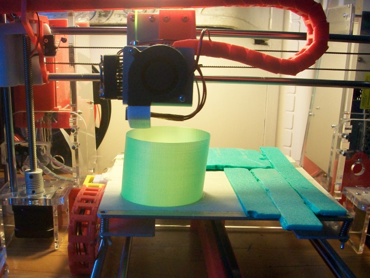
No its not the leaning tower of Piza but it is angled over 5 degrees! :ohmy: It is done so the face of the tube on the bed is 'cut off' at the same angle as the inlet to the Trent nacelle.
The inlet with its shaped inlet and 3 printed 'formers' to give the correct outer profile to the nacelle.

It weighs 18 g.
The exhaust portion of the duct is much shorter and only weighs 3.6 g.

The central 'cone' covers the motor mounting bolts so it will have to be the very last bit to be glued on!
No its not the leaning tower of Piza but it is angled over 5 degrees! :ohmy: It is done so the face of the tube on the bed is 'cut off' at the same angle as the inlet to the Trent nacelle.
The inlet with its shaped inlet and 3 printed 'formers' to give the correct outer profile to the nacelle.
It weighs 18 g.
The exhaust portion of the duct is much shorter and only weighs 3.6 g.
The central 'cone' covers the motor mounting bolts so it will have to be the very last bit to be glued on!
Last edit: 08 Nov 2017 23:05 by Quorneng.
Thanks: Eric, Klipkopwildlife, Ex-Member, THE BLACKBIRD, Ralpharr2001, boz, Squirrelnet
Please Log in or Create an account to join the conversation.
- Quorneng
-
Topic Author
- Offline
- Forum Master
-
Less
More
- Posts: 9436
- Thank you received: 19043
11 Nov 2017 00:56 - 11 Nov 2017 01:01 #14
by Quorneng
Replied by Quorneng on topic A Depron Airbus A350 - 1000 for 76 mm EDFs
After the interlude with the dolls pram its back to A350
The motors and props have arrived.
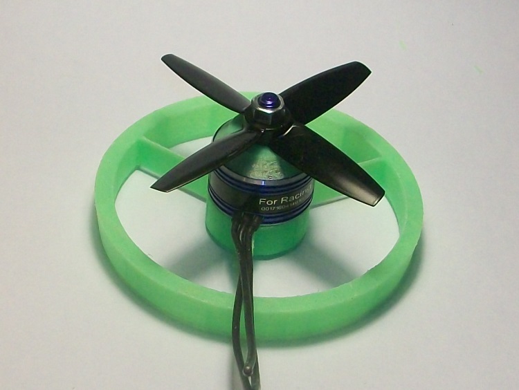
But not without a minor irritation. The motor shaft is threaded and handed with a prop nut supplied to go with the handed props. Thoughtfully each nut is anodised different colour. Fine except they are both LH threads hence the use of an ordinary nut in the picture! Just as well they were both LH rather than RH - I don't have any LH nuts!
The motors and props are for drones although not for the same one!.
At 2300 kV I suspect I will have to use 4S to get sufficient revs for the tiny props.
I would like, but may struggle to get, 200 g of thrust from each.
Much testing required.
The motors and props have arrived.
But not without a minor irritation. The motor shaft is threaded and handed with a prop nut supplied to go with the handed props. Thoughtfully each nut is anodised different colour. Fine except they are both LH threads hence the use of an ordinary nut in the picture! Just as well they were both LH rather than RH - I don't have any LH nuts!
The motors and props are for drones although not for the same one!.
At 2300 kV I suspect I will have to use 4S to get sufficient revs for the tiny props.
I would like, but may struggle to get, 200 g of thrust from each.
Much testing required.
Last edit: 11 Nov 2017 01:01 by Quorneng.
Thanks: Klipkopwildlife, Ex-Member, THE BLACKBIRD, boz, Squirrelnet
Please Log in or Create an account to join the conversation.
- Ex-Member
- User
-
Less
More
- Thank you received: 0
11 Nov 2017 10:35 #15
by Ex-Member
Replied by Ex-Member on topic A Depron Airbus A350 - 1000 for 76 mm EDFs
If the props are for a drone, Q, you might find that the pitch is too fine to produce thrust at anything other than low forward velocity. In fact, above a certain speed, which would be quite low for such a prop, they would act as a brake! The static thrust, on the other hand, would be relatively high.
Please Log in or Create an account to join the conversation.
Time to create page: 0.655 seconds