
- Posts: 9436
- Thank you received: 19043
A Depron Airbus A350 - 1000 for 76 mm EDFs
- Quorneng
-
 Topic Author
- Offline
- Forum Master
-

Less
More
03 Dec 2017 18:42 #46
by Quorneng
Replied by Quorneng on topic A Depron Airbus A350 - 1000 for 76 mm EDFs
A short video of a test run of the 4 blade 3x3.5 in the nacelle wired up with 16 AWG solid magnet wire before the nacelle is glued into the wing.
Runs pretty smoothly but in the video it only on a 2s just to physically test the electrical connections.
Runs pretty smoothly but in the video it only on a 2s just to physically test the electrical connections.
Thanks: Klipkopwildlife, THE BLACKBIRD, boz
Please Log in or Create an account to join the conversation.
- Quorneng
-
Topic Author
- Offline
- Forum Master
-
Less
More
- Posts: 9436
- Thank you received: 19043
04 Dec 2017 20:45 - 04 Dec 2017 20:46 #47
by Quorneng
Replied by Quorneng on topic A Depron Airbus A350 - 1000 for 76 mm EDFs
With all the wiring down each wing and tested the halves can be glued together.
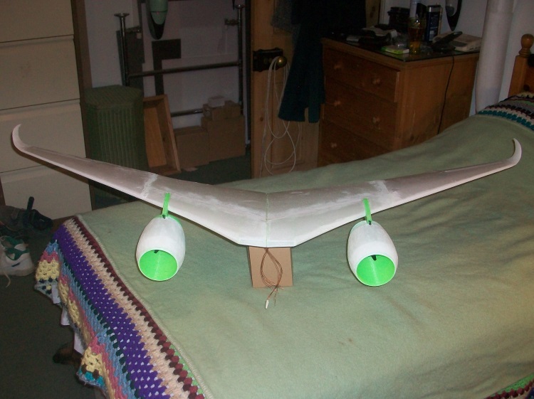
The nacelle pylon glued into wing.

It all weighs 255 g
I only noticed this after I had taken the picture.

The nose of Scooby lying asleep at the side of the bed!
The nacelle pylon glued into wing.
It all weighs 255 g
I only noticed this after I had taken the picture.
The nose of Scooby lying asleep at the side of the bed!
Last edit: 04 Dec 2017 20:46 by Quorneng.
Thanks: Eric, Klipkopwildlife, boz, Squirrelnet
Please Log in or Create an account to join the conversation.
- Quorneng
-
Topic Author
- Offline
- Forum Master
-
Less
More
- Posts: 9436
- Thank you received: 19043
06 Dec 2017 14:09 #48
by Quorneng
Replied by Quorneng on topic A Depron Airbus A350 - 1000 for 76 mm EDFs
Onto the next problem!
The fuselage wing mount was part of the initial 'experimental' centre section although it was incorporated into the actual fuselage. However at the time I had not even considered the wing construction or even its section so to put it simply the wing does not fit properly!
To correct it quite a bit of the fuselage in the area of the wing has to be "re-profiled" which in turn means I have to find a away to modify the un repairable fuselage formers :woohoo:
As it turned out 'printing' some new cross beams and simply gluing them in place proved to be fairly easy.
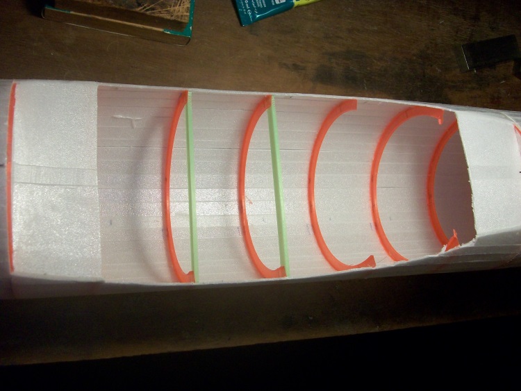
The wing now fits snugly and more important at an appropriate angle of incidence!
On the basis you should always "seek a benefit from a mistake" having the underside of the fuselage temporarily 'open' will make it much easier to run the elevator and rudder servo wires along the fuselage so before going any further the tailplane and fin are next!
The fuselage wing mount was part of the initial 'experimental' centre section although it was incorporated into the actual fuselage. However at the time I had not even considered the wing construction or even its section so to put it simply the wing does not fit properly!
To correct it quite a bit of the fuselage in the area of the wing has to be "re-profiled" which in turn means I have to find a away to modify the un repairable fuselage formers :woohoo:
As it turned out 'printing' some new cross beams and simply gluing them in place proved to be fairly easy.
The wing now fits snugly and more important at an appropriate angle of incidence!
On the basis you should always "seek a benefit from a mistake" having the underside of the fuselage temporarily 'open' will make it much easier to run the elevator and rudder servo wires along the fuselage so before going any further the tailplane and fin are next!
Thanks: Klipkopwildlife, THE BLACKBIRD, boz
Please Log in or Create an account to join the conversation.
- Mike Rolls
-

- Offline
- Elite Member
-

Less
More
- Posts: 634
- Thank you received: 573
06 Dec 2017 14:20 #49
by Mike Rolls
The older I get, the better I was!
Replied by Mike Rolls on topic A Depron Airbus A350 - 1000 for 76 mm EDFs
Whilst I stand (or sit!) in awe at what can be produced by 3D printing - those beams are simple bits of straight material. Why print them? They would have taken seconds only to cut from balsa or spruce. depending on the level of strength you wanted.
Mike
Mike
The older I get, the better I was!
Please Log in or Create an account to join the conversation.
- Quorneng
-
Topic Author
- Offline
- Forum Master
-
Less
More
- Posts: 9436
- Thank you received: 19043
06 Dec 2017 18:10 #50
by Quorneng
Replied by Quorneng on topic A Depron Airbus A350 - 1000 for 76 mm EDFs
Mike
Printed for no reason other than I wanted to see if it was possible to do a 'repair' on a printed component.
Not quite 'simple' beams as each end had a radius that automatically matches the fuselage curvature depending on how long each beam is. A benefit of being 'mathematically' generated.

Yes a straight beam this case but the same process could be used to create a 'part' of a much more complicated print.
Each 10 x 3 mm printed beam is about the same strength and weight as softish balsa but being a U channel it does not have the same torsional resistance however in this application there is no torsion loading.
Printed for no reason other than I wanted to see if it was possible to do a 'repair' on a printed component.
Not quite 'simple' beams as each end had a radius that automatically matches the fuselage curvature depending on how long each beam is. A benefit of being 'mathematically' generated.
Yes a straight beam this case but the same process could be used to create a 'part' of a much more complicated print.
Each 10 x 3 mm printed beam is about the same strength and weight as softish balsa but being a U channel it does not have the same torsional resistance however in this application there is no torsion loading.
Thanks: Klipkopwildlife, THE BLACKBIRD, boz
Please Log in or Create an account to join the conversation.
- Quorneng
-
Topic Author
- Offline
- Forum Master
-
Less
More
- Posts: 9436
- Thank you received: 19043
08 Dec 2017 12:50 - 08 Dec 2017 12:51 #51
by Quorneng
Replied by Quorneng on topic A Depron Airbus A350 - 1000 for 76 mm EDFs
The fairly modest tailplane although the elevator is quite generous in proportion.

2 mm Depron skins with no ribs. A printed U channel spar supports the elevators but the elevators themselves have a hard balsa leading edge to give extra torsional stiffness. The horn will be on the inner edge as the tailplane is only thick enough to contain the micro servo near the root.
The fin will be fixed to the tailplane and the fuselage cut open to insert the whole assembly. Well that's the plan.
Last edit: 08 Dec 2017 12:51 by Quorneng.
Thanks: Klipkopwildlife, THE BLACKBIRD, boz, Mike Rolls, Squirrelnet
Please Log in or Create an account to join the conversation.
- Firewood
-

- Offline
- Elite Member
-
Less
More
- Posts: 219
- Thank you received: 268
08 Dec 2017 14:54 #52
by Firewood
I'm so clever that sometimes I don't understand a single word of what I'm saying.
Replied by Firewood on topic A Depron Airbus A350 - 1000 for 76 mm EDFs
I have been watching your build with great interest but what I cannot understand is you have no longitudinal stringers and the depron for the shell is so very thin where does the airframe get its strength from?
I'm so clever that sometimes I don't understand a single word of what I'm saying.
Thanks: boz, Squirrelnet
Please Log in or Create an account to join the conversation.
- Quorneng
-
Topic Author
- Offline
- Forum Master
-
Less
More
- Posts: 9436
- Thank you received: 19043
08 Dec 2017 17:57 #53
by Quorneng
Replied by Quorneng on topic A Depron Airbus A350 - 1000 for 76 mm EDFs
Firewood
Depron is a fine cell foam made of polystyrene which was one of the early 'engineering' plastics. For its weight polystyrene has a strength not dissimilar to wood so Depron sheet actually has quite a reasonable strength to weight ratio. In addition the way it is formed gives it a denser top and bottom skin making the sheet a sandwich better able to resist compression loads.
The trick is to make use of its strength to weight by spreading the loads as evenly as possible over a large area of Depron.
For example, 2 mm Depron has about the same weight as fairly soft 0.8 mm (1/32) balsa. Although such balsa has a higher tensile strength it will buckle in compression very easily compared to the relative thick Depron sheet. To use such balsa would require much close spaced internal support.
Clearly the 2 mm Depron skin of the fuselage is not a strong as a conventional built up balsa structure but it is very much lighter so gives a comparable, and possibly superior, strength to weight but this has to be matched by the rest of the plane.
The same principle was applied to the DH Mosquito fuselage. Its thick (1") Ply/balsa/ply sandwich skin needed little or no internal support between its relatively few fuselage formers.
Thanks: Klipkopwildlife, boz, Firewood, Squirrelnet
Please Log in or Create an account to join the conversation.
- Quorneng
-
Topic Author
- Offline
- Forum Master
-
Less
More
- Posts: 9436
- Thank you received: 19043
09 Dec 2017 22:06 - 09 Dec 2017 22:08 #54
by Quorneng
Replied by Quorneng on topic A Depron Airbus A350 - 1000 for 76 mm EDFs
Grand kids - all four - round today so not that much done.
The fin fixed to the tail plane.

It appears on the full size the fin spar passes in front of the tail plane so it needed a few printed brackets to support it securely and at the correct sweep angle.
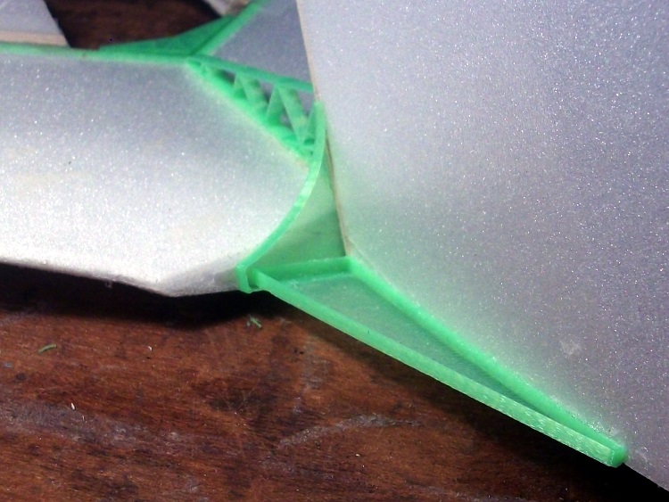
All the brackets will be hidden inside the fuselage.
Elevator and rudder servos next but still thinking exactly where to position them.
The fin fixed to the tail plane.
It appears on the full size the fin spar passes in front of the tail plane so it needed a few printed brackets to support it securely and at the correct sweep angle.
All the brackets will be hidden inside the fuselage.
Elevator and rudder servos next but still thinking exactly where to position them.
Last edit: 09 Dec 2017 22:08 by Quorneng.
Thanks: Klipkopwildlife, THE BLACKBIRD, boz
Please Log in or Create an account to join the conversation.
- Ex-Member
- User
-

Less
More
- Thank you received: 0
10 Dec 2017 07:21 #55
by Ex-Member
Replied by Ex-Member on topic A Depron Airbus A350 - 1000 for 76 mm EDFs
I do like those brackets, Q, nicely done! 
Did you by any chance weigh them before fixing to the model, I'd be interested to know their weight?
Did you by any chance weigh them before fixing to the model, I'd be interested to know their weight?
Please Log in or Create an account to join the conversation.
- Quorneng
-
Topic Author
- Offline
- Forum Master
-
Less
More
- Posts: 9436
- Thank you received: 19043
10 Dec 2017 23:39 #56
by Quorneng
Replied by Quorneng on topic A Depron Airbus A350 - 1000 for 76 mm EDFs
There are 4 brackets used to hold the fin and tail plane together. I do have duplicates of 3 of them.

Together they weigh 1.4 g.
The fourth is similar in size so close to 2 g for all four.
They are not 'simple' triangles either. One side is a curve to match the surface of the tail plane or fin.
My judgement is to be of the same stiffness they would be about the same weight in balsa.
The primary function of the brackets is to hold the fin and tail plane is their correct positions as a 'stand alone' assembly. The fuselage formers & skin will add significant further stiffness when it is restored around them.
Thanks: Klipkopwildlife, THE BLACKBIRD, Ex-Member, boz, Mike Rolls, Squirrelnet
Please Log in or Create an account to join the conversation.
- Ex-Member
- User
-
Less
More
- Thank you received: 0
11 Dec 2017 07:00 #57
by Ex-Member
Replied by Ex-Member on topic A Depron Airbus A350 - 1000 for 76 mm EDFs
Thanks Q.
Yours' and Tony's development of 3D printing is proving to be both interesting and practical. Well done and thanks for posting.
Yours' and Tony's development of 3D printing is proving to be both interesting and practical. Well done and thanks for posting.
Please Log in or Create an account to join the conversation.
- Klipkopwildlife
-

- Offline
- Administrator
-

- I'm supposed to be retired!
11 Dec 2017 08:14 #58
by Klipkopwildlife
Do it now, you may never get another chance
Replied by Klipkopwildlife on topic A Depron Airbus A350 - 1000 for 76 mm EDFs
Think of it as a tube, it's very easy to crush a tube from the side but surprisingly difficult to bend it or twist it.Firewood wrote: I have been watching your build with great interest but what I cannot understand is you have no longitudinal stringers and the depron for the shell is so very thin where does the airframe get its strength from?
Do it now, you may never get another chance
Thanks: boz, Firewood
Please Log in or Create an account to join the conversation.
- Quorneng
-
Topic Author
- Offline
- Forum Master
-
Less
More
- Posts: 9436
- Thank you received: 19043
11 Dec 2017 23:41 #59
by Quorneng
Replied by Quorneng on topic A Depron Airbus A350 - 1000 for 76 mm EDFs
Whilst I am happy using top tap hinges for the ailerons and elevator seems a bit 'untidy' to doso on the rudder.
As the A350 fin has a balsa spar to support the rudder I needed some proper but very small hinges, at;east 3 and maybe 4.
I have made hinges using acetate sheet before but in this case I needed something more like a Robart hinge which I don't have.
So I tried printing some!
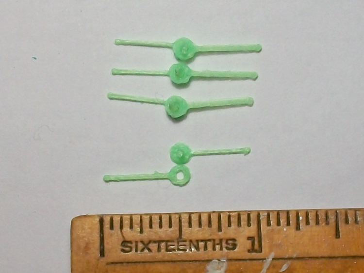
Two parts - the long pin is squashed down with a low temperature soldering iron to retain the hinge.
I was trying to find the smallest thing that could be succesfully printed but I will actually need them to be a bit bigger than this!
As the A350 fin has a balsa spar to support the rudder I needed some proper but very small hinges, at;east 3 and maybe 4.
I have made hinges using acetate sheet before but in this case I needed something more like a Robart hinge which I don't have.
So I tried printing some!
Two parts - the long pin is squashed down with a low temperature soldering iron to retain the hinge.
I was trying to find the smallest thing that could be succesfully printed but I will actually need them to be a bit bigger than this!
Thanks: Klipkopwildlife, Ex-Member, Ralpharr2001, boz, Squirrelnet
Please Log in or Create an account to join the conversation.
- Quorneng
-
Topic Author
- Offline
- Forum Master
-
Less
More
- Posts: 9436
- Thank you received: 19043
12 Dec 2017 23:58 - 13 Dec 2017 00:02 #60
by Quorneng
Replied by Quorneng on topic A Depron Airbus A350 - 1000 for 76 mm EDFs
The "Mk2" hinge.
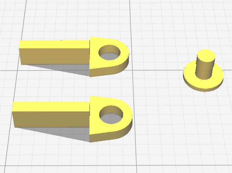
Two identical components with a separate hinge pin.
The stepped pin is a loose fit in one arm and tight in the other. A dab of glue on the outer surface secures the pin.
i know the pin looks to be too small a diameter but when printed it is just the right size.
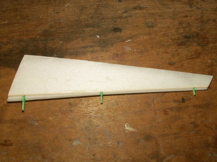
The rudder assembly with three hinges printed at 100, 125 and 150% to suit the rudder thickness.
Still thinking about the final servo placement which probably means as soon as I decide I will think of a better alternative!
Two identical components with a separate hinge pin.
The stepped pin is a loose fit in one arm and tight in the other. A dab of glue on the outer surface secures the pin.
i know the pin looks to be too small a diameter but when printed it is just the right size.
The rudder assembly with three hinges printed at 100, 125 and 150% to suit the rudder thickness.
Still thinking about the final servo placement which probably means as soon as I decide I will think of a better alternative!
Last edit: 13 Dec 2017 00:02 by Quorneng.
Thanks: Klipkopwildlife, boz, Firewood
Please Log in or Create an account to join the conversation.
Time to create page: 1.507 seconds