
- Thank you received: 0
Blackburn 1912 Monoplane - 48" (1220mm) PAW Diesel
- Ex-Member
- Topic Author
- User
-

Less
More
08 Feb 2015 18:26 #16
by Ex-Member
Replied by Ex-Member on topic Blackburn 1912 Monoplane - 48" (1220mm) PAW Diesel
Thanks Tony!
Today's work continued with tidying up the wings, cutting the wing tip cores and fitting them to the wings:

A trial assembly to see how she looks

Then the fiddly bit - cutting the diagonal bracing struts for the rear end. Blackburn fitted them in the opposite sense on either side of the fus. The 1/32" x 1/8" laminations for the wing tips are at the bottom of the phot:

The empennage was tidied up too, but no photo of that.
Today's work continued with tidying up the wings, cutting the wing tip cores and fitting them to the wings:
A trial assembly to see how she looks
Then the fiddly bit - cutting the diagonal bracing struts for the rear end. Blackburn fitted them in the opposite sense on either side of the fus. The 1/32" x 1/8" laminations for the wing tips are at the bottom of the phot:
The empennage was tidied up too, but no photo of that.
Please Log in or Create an account to join the conversation.
- Ex-Member
- Topic Author
- User
-
Less
More
- Thank you received: 0
09 Feb 2015 08:04 #17
by Ex-Member
Replied by Ex-Member on topic Blackburn 1912 Monoplane - 48" (1220mm) PAW Diesel
I've tidied the rear control surfaces and the glue is currently drying on the top fuselage formers - stringers next, then fixings and accessories for the UC, wings and engine:

By way of a contrast, I've put the fuselage, an elevator and rudder of the last model I was working on in the picture, a 13" span Westland Woodpigeon......I'll leave you to your own conclusion!
By way of a contrast, I've put the fuselage, an elevator and rudder of the last model I was working on in the picture, a 13" span Westland Woodpigeon......I'll leave you to your own conclusion!
Please Log in or Create an account to join the conversation.
- Ex-Member
- Topic Author
- User
-
Less
More
- Thank you received: 0
09 Feb 2015 08:05 #18
by Ex-Member
Replied by Ex-Member on topic Blackburn 1912 Monoplane - 48" (1220mm) PAW Diesel
I've tidied the rear control surfaces and the glue is currently drying on the top fuselage formers - stringers next, then fixings and accessories for the UC, wings and engine:
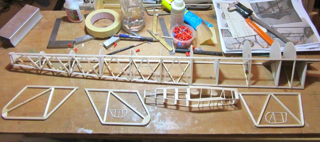
By way of a contrast, I've put the fuselage, an elevator and rudder of the last model I was working on in the picture, a 13" span Westland Woodpigeon......I'll leave you to your own conclusion!
By way of a contrast, I've put the fuselage, an elevator and rudder of the last model I was working on in the picture, a 13" span Westland Woodpigeon......I'll leave you to your own conclusion!
Please Log in or Create an account to join the conversation.
- Quorneng
-

- Offline
- Forum Master
-

Less
More
- Posts: 9436
- Thank you received: 19043
09 Feb 2015 11:47 #19
by Quorneng
Replied by Quorneng on topic Blackburn 1912 Monoplane - 48" (1220mm) PAW Diesel
Very pretty but looking at the delicacy of the construction I am amazed you are thinking of putting any sort of IC engine in it! :woohoo:
Please Log in or Create an account to join the conversation.
- Ex-Member
- Topic Author
- User
-
Less
More
- Thank you received: 0
09 Feb 2015 18:59 #20
by Ex-Member
Complex, yes, but I wouldn't have called it delicate Q. Most of the balsa is medium to medium hard grade and there's a good dollop of aliphatic resin on each joint. The covering will be silk over tissue which will further hold it together, so I'm confident it'll stand up well to the required task.
As an aside, the cross bracing is an addition to the original plan, but it's scale and can be seen through the translucent covering, so it should be there. I've also added cores to the wing tips to give them enough strength to cope with the knocks a FF model will inevitably get. They'll show though the covering as non-scale, but I'll take the hit on that as the tips would be very weak otherwise.
Replied by Ex-Member on topic Blackburn 1912 Monoplane - 48" (1220mm) PAW Diesel
Quorneng wrote: Very pretty but looking at the delicacy of the construction I am amazed you are thinking of putting any sort of IC engine in it! :woohoo:
Complex, yes, but I wouldn't have called it delicate Q. Most of the balsa is medium to medium hard grade and there's a good dollop of aliphatic resin on each joint. The covering will be silk over tissue which will further hold it together, so I'm confident it'll stand up well to the required task.
As an aside, the cross bracing is an addition to the original plan, but it's scale and can be seen through the translucent covering, so it should be there. I've also added cores to the wing tips to give them enough strength to cope with the knocks a FF model will inevitably get. They'll show though the covering as non-scale, but I'll take the hit on that as the tips would be very weak otherwise.
Please Log in or Create an account to join the conversation.
- Ex-Member
- Topic Author
- User
-
Less
More
- Thank you received: 0
10 Feb 2015 20:23 - 10 Feb 2015 20:27 #21
by Ex-Member
Replied by Ex-Member on topic Blackburn 1912 Monoplane - 48" (1220mm) PAW Diesel
Stringers have been cut and glued to the rear fus:

The work in the foreground is an 80% Veron Sea Hawk fuselage under construction - see thread: www.aeromodellers.co.uk/forum/free-fligh...wk-for-rapier-rocket
The work in the foreground is an 80% Veron Sea Hawk fuselage under construction - see thread: www.aeromodellers.co.uk/forum/free-fligh...wk-for-rapier-rocket
Last edit: 10 Feb 2015 20:27 by Ex-Member. Reason: Add description
Please Log in or Create an account to join the conversation.
- Ex-Member
- User
-
Less
More
- Thank you received: 0
10 Feb 2015 20:59 #22
by Ex-Member
Replied by Ex-Member on topic Blackburn 1912 Monoplane - 48" (1220mm) PAW Diesel
looking great Andy.
smashing work
smashing work
Please Log in or Create an account to join the conversation.
- Ex-Member
- Topic Author
- User
-
Less
More
- Thank you received: 0
11 Feb 2015 13:14 #23
by Ex-Member
Replied by Ex-Member on topic Blackburn 1912 Monoplane - 48" (1220mm) PAW Diesel
Wing tips have been laminated in situ (won't be doing that again!) from 4 x water soaked 1/8" x 1/32" balsa strips.
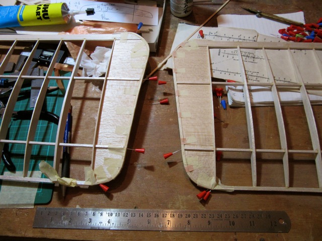
Further work has included marking out the positions of the UC and wing tubes in the fus - not worth a picture yet as still working out the sizes of the pylon and UC legs and deciding how they will be supported.
Also waiting for a warm day (like last Monday) so I can go outside and do some serious sanding. :lol: :lol:
Please Log in or Create an account to join the conversation.
- Ex-Member
- Topic Author
- User
-
Less
More
- Thank you received: 0
12 Feb 2015 12:49 - 12 Feb 2015 12:51 #24
by Ex-Member
Replied by Ex-Member on topic Blackburn 1912 Monoplane - 48" (1220mm) PAW Diesel
The wing tubes are in place and epoxy'd. The wings will be separated when the epoxy's dry:
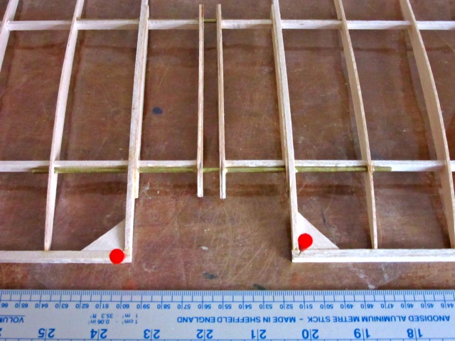

The board was propped up on the landing (pun intended) for the photo only; it's now laying flat in the workshop for the epoxy to set hard
The board was propped up on the landing (pun intended) for the photo only; it's now laying flat in the workshop for the epoxy to set hard
Last edit: 12 Feb 2015 12:51 by Ex-Member.
Please Log in or Create an account to join the conversation.
- martynk
-
- Offline
- Premium Member
-

12 Feb 2015 16:50 - 12 Feb 2015 16:51 #25
by martynk
--
Martyn
mad-aeromodeller.blogspot.co.uk/
Replied by martynk on topic Blackburn 1912 Monoplane - 48" (1220mm) PAW Diesel
That's is moving on so quickly - looks wonderful.
I love these proper open structures. I have got very blasé over the years with heavy all sheet aerobatic models, it's really nice being back to sticks and tissue again.
This was my last stick and (err) film model - a 1982 Peter Russell STOL - AUW for a 25 sized model of just over 1kg (completed last week).

I thoroughly enjoyed building that
I love these proper open structures. I have got very blasé over the years with heavy all sheet aerobatic models, it's really nice being back to sticks and tissue again.
This was my last stick and (err) film model - a 1982 Peter Russell STOL - AUW for a 25 sized model of just over 1kg (completed last week).
I thoroughly enjoyed building that
--
Martyn
mad-aeromodeller.blogspot.co.uk/
Last edit: 12 Feb 2015 16:51 by martynk.
Thanks: Klipkopwildlife, old fart
Please Log in or Create an account to join the conversation.
- Ex-Member
- Topic Author
- User
-
Less
More
- Thank you received: 0
13 Feb 2015 19:29 #26
by Ex-Member
Replied by Ex-Member on topic Blackburn 1912 Monoplane - 48" (1220mm) PAW Diesel
The wing halves have again been split and the tubes tidied:

Further tubes, piano wire dowels and balsa spacer pieces have been cut to enable a trial assembly to check the wing positioning on the fus (dihedral will be bent into the dowels when ready for final assembly - for setting up there is no dihedral:


Further tubes, piano wire dowels and balsa spacer pieces have been cut to enable a trial assembly to check the wing positioning on the fus (dihedral will be bent into the dowels when ready for final assembly - for setting up there is no dihedral:
Please Log in or Create an account to join the conversation.
- Ex-Member
- Topic Author
- User
-
Less
More
- Thank you received: 0
14 Feb 2015 17:49 - 14 Feb 2015 17:53 #27
by Ex-Member
Replied by Ex-Member on topic Blackburn 1912 Monoplane - 48" (1220mm) PAW Diesel
Not much to see today, although I spent a lot of time researching and drawing.
The wings on the model are set at 7 deg incidence, but according to the write up, it needs a few degrees of down on the tailplane. On checking the full size, it appears that the wings are at 5 deg, so the model has been re-drawn and I now have a datum for the wing tubes. The cockpit opening was also wrong on the model plan, so that too has been corrected:

The jigging block for the front wing tube have been cut and glued to the front of former F5, the gap in the jigging block is for the wing pylon:

The wings on the model are set at 7 deg incidence, but according to the write up, it needs a few degrees of down on the tailplane. On checking the full size, it appears that the wings are at 5 deg, so the model has been re-drawn and I now have a datum for the wing tubes. The cockpit opening was also wrong on the model plan, so that too has been corrected:
The jigging block for the front wing tube have been cut and glued to the front of former F5, the gap in the jigging block is for the wing pylon:
Last edit: 14 Feb 2015 17:53 by Ex-Member.
Please Log in or Create an account to join the conversation.
- Ex-Member
- Topic Author
- User
-
Less
More
- Thank you received: 0
15 Feb 2015 15:20 #28
by Ex-Member
Replied by Ex-Member on topic Blackburn 1912 Monoplane - 48" (1220mm) PAW Diesel
It's a day for small jobs with drying time inbetween today:
So far, the front wing tube was tack-epoxied into position:

Followed by the rear wing tube using the wing as a jig:

So far, the front wing tube was tack-epoxied into position:
Followed by the rear wing tube using the wing as a jig:
Please Log in or Create an account to join the conversation.
- Quorneng
-
- Offline
- Forum Master
-
Less
More
- Posts: 9436
- Thank you received: 19043
15 Feb 2015 15:41 #29
by Quorneng
Replied by Quorneng on topic Blackburn 1912 Monoplane - 48" (1220mm) PAW Diesel
Wow!
I presume the rigging is going to be very real.
I presume the rigging is going to be very real.
Please Log in or Create an account to join the conversation.
- Ex-Member
- Topic Author
- User
-
Less
More
- Thank you received: 0
15 Feb 2015 16:56 #30
by Ex-Member
Oh yes!
There will be some local reinforcement around the tubes and they will eventually be bound to the structure, but as they only have to act in shear, 16 swg (or 1.5mm in this case) should be more than sufficient.
Replied by Ex-Member on topic Blackburn 1912 Monoplane - 48" (1220mm) PAW Diesel
Quorneng wrote: Wow!
I presume the rigging is going to be very real.
Oh yes!
There will be some local reinforcement around the tubes and they will eventually be bound to the structure, but as they only have to act in shear, 16 swg (or 1.5mm in this case) should be more than sufficient.
Please Log in or Create an account to join the conversation.
Time to create page: 1.196 seconds