
- Posts: 13729
- Thank you received: 14473
freeCAD and fuselage creation
- Eric
-

- Offline
- Moderator
-

Less
More
19 May 2022 10:22 #76
by Eric
if you are calm and collected when all about you are going berserk - you've missed something important!
Replied by Eric on topic freeCAD and fuselage creation
Is it thicker or thinner than the wing at the join?
Thinner won't be that critical - but if it is significantly thicker, that may give rise to some weird behaviour!
The airflow will turbulate at the hinge-line, so you might get either NO response, or reversed aileron effect, because the surface may 'stall'.
Also - depending on how 'stiff' the control link is, you may get surface flutter.
if you are calm and collected when all about you are going berserk - you've missed something important!
Thanks: Klipkopwildlife, jon.in.swansea
Please Log in or Create an account to join the conversation.
- Quorneng
-

- Offline
- Forum Master
-

Less
More
- Posts: 9436
- Thank you received: 19043
19 May 2022 12:49 - 19 May 2022 12:53 #77
by Quorneng
Replied by Quorneng on topic freeCAD and fuselage creation
I would say that it is better for the control surface to follow the line of the wing skin. Conventionally the upper surface is considered more important as the air flow is moving faster and is more easily disturbed,
The most likely effect from a control surface "step" would be a reduction or even a lck of any control effectiveness at small deflections but the maximum effect at full travel is not likely to be reduced.
The interesting bit will be whether you find the revised plane is any better, worse or just different to fly.
You will know the instant you have arived at a "good" plane. Then the only problem is trying to work out the what & why that makes it so! :woohoo:
Last edit: 19 May 2022 12:53 by Quorneng.
Thanks: Klipkopwildlife, jon.in.swansea
Please Log in or Create an account to join the conversation.
- jon.in.swansea
-
 Topic Author
- Offline
- Elite Member
-

Less
More
- Posts: 766
- Thank you received: 1192
19 May 2022 16:21 #78
by jon.in.swansea
Replied by jon.in.swansea on topic freeCAD and fuselage creation
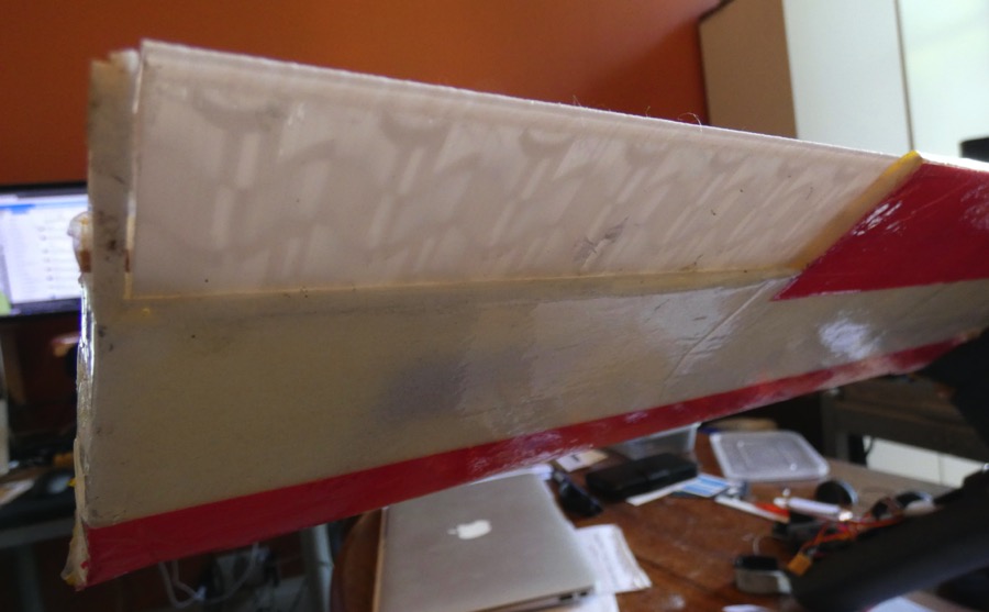
I took some photos of the larger Clarke-Y wing ailerons top and bottom. At this scale there is a minor drop. I could potentially remove a bit of the tape and sand the skin down a bit to reduce the step. It might be easier to glue on 2mm of foam to the top surface of the aileron.

For the smaller scale wing the drop is more pronounced, especially as the aileron chord is short. I have not finished the surface so it would be easier to sand down the skin to make the drop less abrupt. At this scale I suspect I should bulk up the aileron, perhaps by gluing on 2mm foam to it on at least the top surface. In future I would probably be better to scale up the print so that it followed the line of the skin.
-Jon
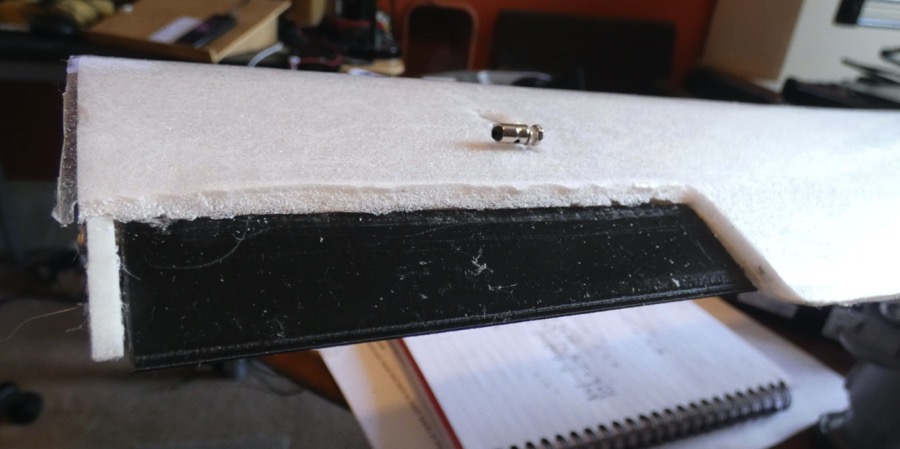
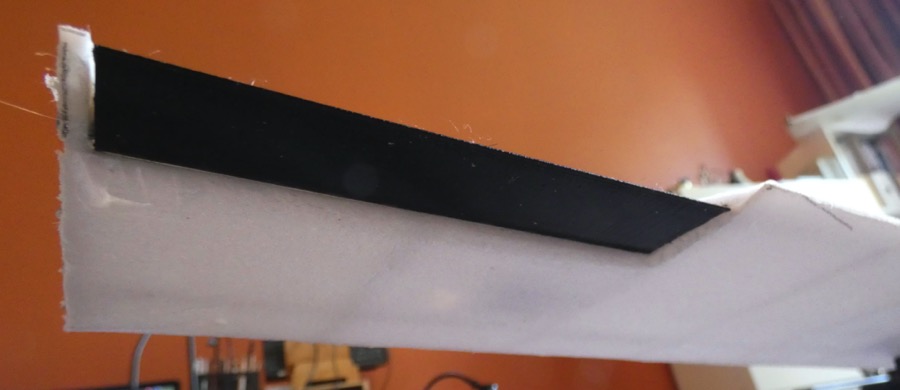
For the smaller scale wing the drop is more pronounced, especially as the aileron chord is short. I have not finished the surface so it would be easier to sand down the skin to make the drop less abrupt. At this scale I suspect I should bulk up the aileron, perhaps by gluing on 2mm foam to it on at least the top surface. In future I would probably be better to scale up the print so that it followed the line of the skin.
-Jon
Thanks: Klipkopwildlife, THE BLACKBIRD
Please Log in or Create an account to join the conversation.
- Eric
-
- Offline
- Moderator
-
Less
More
- Posts: 13729
- Thank you received: 14473
19 May 2022 20:15 #79
by Eric
if you are calm and collected when all about you are going berserk - you've missed something important!
Replied by Eric on topic freeCAD and fuselage creation
Yes - make the aileron thicker, and also extend the inboard edge to match the wing trailing edge profile - unless you WANT lots of tip vortex drag!
if you are calm and collected when all about you are going berserk - you've missed something important!
Thanks: Klipkopwildlife, jon.in.swansea
Please Log in or Create an account to join the conversation.
- Quorneng
-
- Offline
- Forum Master
-
Less
More
- Posts: 9436
- Thank you received: 19043
19 May 2022 21:54 #80
by Quorneng
Replied by Quorneng on topic freeCAD and fuselage creation
jon
A nice design task.
See if you can print a new bigger thicker aileron for the same weight.
A nice design task.
See if you can print a new bigger thicker aileron for the same weight.
Thanks: Klipkopwildlife, jon.in.swansea
Please Log in or Create an account to join the conversation.
- jon.in.swansea
-
Topic Author
- Offline
- Elite Member
-
Less
More
- Posts: 766
- Thank you received: 1192
20 May 2022 14:41 - 20 May 2022 14:46 #81
by jon.in.swansea
Replied by jon.in.swansea on topic freeCAD and fuselage creation
I have been looking into how to do scaling on a sketch. Thus far I have managed to take the outline of the Clarke-Y and scale & transform to a half dozen outlines that have lofted to something that looks like a winglet to potentially glue onto the ends, especially if I alter one of the axis scales - ~5g each. I am printing a test one and will post a photo for folk to chuckle at. Just because I manage to get freeCAD to do something does not necessarily result in it getting used...


I think I should be able to upscale the aileron - I think I can drop from 10% infil to 5% infil to limit the weight gains..... -Jon
I think I should be able to upscale the aileron - I think I can drop from 10% infil to 5% infil to limit the weight gains..... -Jon
Last edit: 20 May 2022 14:46 by jon.in.swansea.
Thanks: Klipkopwildlife, Quorneng
Please Log in or Create an account to join the conversation.
- jon.in.swansea
-
Topic Author
- Offline
- Elite Member
-
Less
More
- Posts: 766
- Thank you received: 1192
21 May 2022 18:12 #82
by jon.in.swansea
Replied by jon.in.swansea on topic freeCAD and fuselage creation
I got the larger aileron printed out with only an 0.5g extra weight! 5% infil seems rigid enough.
One irritant that I found in freeCAD - I had a prior sketch that I partly wanted to borrow points from. I could not find how to copy them unless I copied the whole lot, added in the poly lines I needed and then delete the unwanted points/lines one by one. -Jon
One irritant that I found in freeCAD - I had a prior sketch that I partly wanted to borrow points from. I could not find how to copy them unless I copied the whole lot, added in the poly lines I needed and then delete the unwanted points/lines one by one. -Jon
Thanks: Eric, Klipkopwildlife
Please Log in or Create an account to join the conversation.
- Quorneng
-
- Offline
- Forum Master
-
Less
More
- Posts: 9436
- Thank you received: 19043
21 May 2022 22:56 #83
by Quorneng
Replied by Quorneng on topic freeCAD and fuselage creation
jon
Can't help. like you I have found the copy s sketch to be "all or nothing" in Free Cad. I am not suggesting it can't be done but I have not discovered howyet!
Can't help. like you I have found the copy s sketch to be "all or nothing" in Free Cad. I am not suggesting it can't be done but I have not discovered howyet!
Thanks: Klipkopwildlife, jon.in.swansea
Please Log in or Create an account to join the conversation.
- jon.in.swansea
-
Topic Author
- Offline
- Elite Member
-
Less
More
- Posts: 766
- Thank you received: 1192
31 May 2022 14:10 #84
by jon.in.swansea
Replied by jon.in.swansea on topic freeCAD and fuselage creation
I needed a fuselage to go with my shiny new Clarke-Y wing (115mm chord 700mm span ~110g weight). My much used Franken Pod fuselages were overly hefty and would have resulted in a horrible wing loading. I had been getting better at my cad skills and had taken delivery of some rather nice and light 8mm carbon fibre arrow shafts to use as booms so time to design something sleek, light and better suited to the new wing.
Below are three montages showing the process.
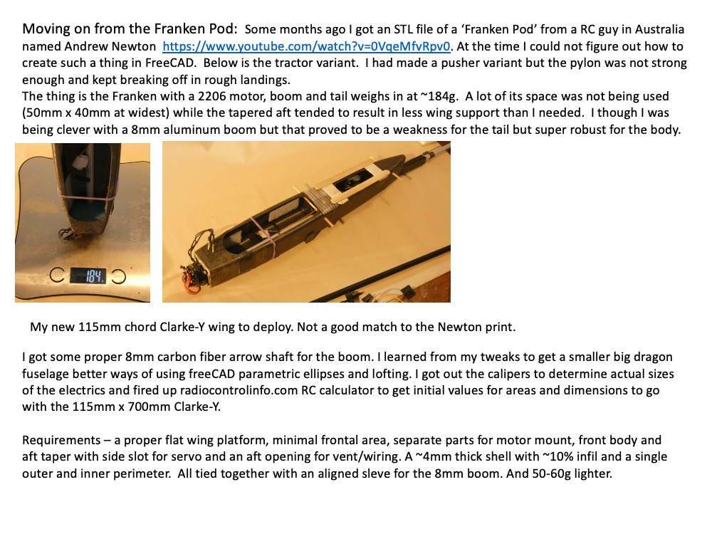

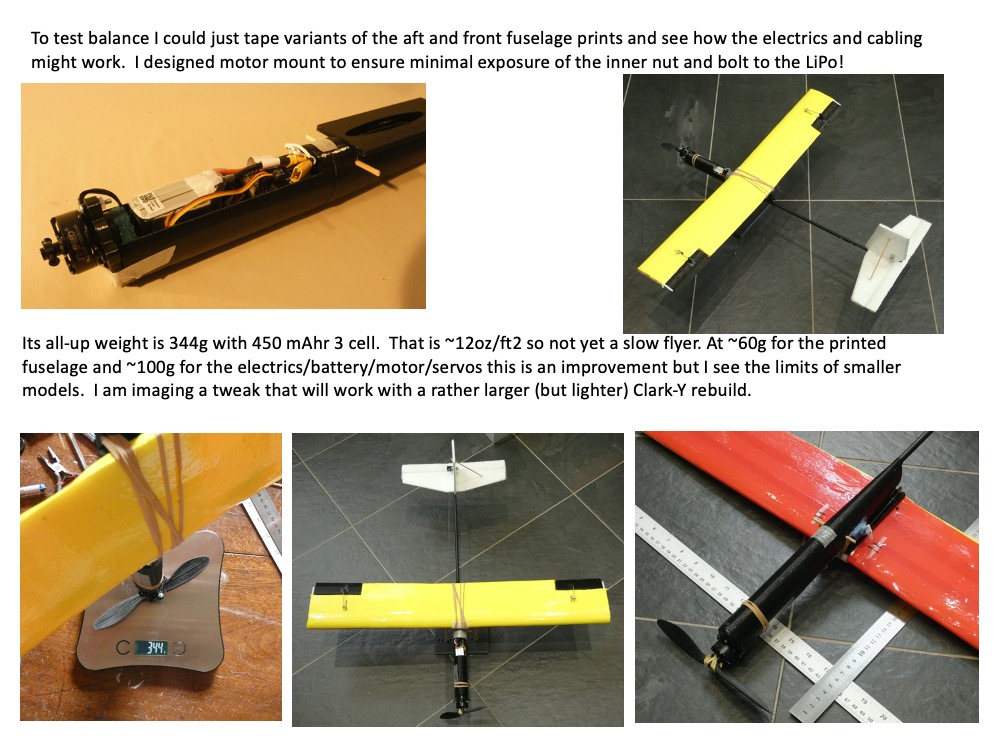
I like it that it is about a minutes effort to alter the length of the main body of the fuselage and only a couple of minutes to tweak the aft section to work with different wing chords and also that it is simple to print variant motor mounts and can mix & match them all.
I took it out for a maiden yesterday - remember that this was first flight of this small Clarke-Y, it was the first push-pull elevator control, it was a new boom, new fuselage etc. I kept the same Futaba T6L sport transmitter and its receiver - changing over to a new transmitter on a maiden is a step to far...
I did initial balance with COG at ~26%. In a mild breeze it was a bit skittish but it took off at half throttle and ran nicely at 25% with a 3 cell. It needed a slight bit more speed than I was hoping for but does seem to glide nicely.
Today I got to grips with the new Futaba T6K, paired it with the old receiver, dialled in a tiny bit of exponential for the ailerons and elevator and took it out in near still conditions. Ran through two batteries before I had to leave the park because a grass cutting crew had defended on the place.
If those videos come out I will post about them on the 'been flying'.
As always - comments welcome. I am rather chuffed with the cad design and if anyone wants I will upload the files. -Jon
Below are three montages showing the process.
I like it that it is about a minutes effort to alter the length of the main body of the fuselage and only a couple of minutes to tweak the aft section to work with different wing chords and also that it is simple to print variant motor mounts and can mix & match them all.
I took it out for a maiden yesterday - remember that this was first flight of this small Clarke-Y, it was the first push-pull elevator control, it was a new boom, new fuselage etc. I kept the same Futaba T6L sport transmitter and its receiver - changing over to a new transmitter on a maiden is a step to far...
I did initial balance with COG at ~26%. In a mild breeze it was a bit skittish but it took off at half throttle and ran nicely at 25% with a 3 cell. It needed a slight bit more speed than I was hoping for but does seem to glide nicely.
Today I got to grips with the new Futaba T6K, paired it with the old receiver, dialled in a tiny bit of exponential for the ailerons and elevator and took it out in near still conditions. Ran through two batteries before I had to leave the park because a grass cutting crew had defended on the place.
If those videos come out I will post about them on the 'been flying'.
As always - comments welcome. I am rather chuffed with the cad design and if anyone wants I will upload the files. -Jon
Thanks: Klipkopwildlife, Quorneng
Please Log in or Create an account to join the conversation.
- Quorneng
-
- Offline
- Forum Master
-
Less
More
- Posts: 9436
- Thank you received: 19043
31 May 2022 16:01 #85
by Quorneng
Replied by Quorneng on topic freeCAD and fuselage creation
jon
Looking at the proportions of your latest iteration I would think you could increase the span to 1000 mm without changing anything else..
If the root is strong enough you would be simply extending the outer parts of the wing structure which do not weigh much. It should result in a 30% increase in wing area for maybe only a 10%% increase in the weight of the wing. This sort of thing results in a significant reduction in the wing loading.
A parallel chord wing is relatively simple to make but is far from the ideal structurally. A tapered wing get much closer to providing the strength where it is needed. Deep at the root, thinner towards the tip.
As an example this is the comparison between the root and tip wing sections of my scale 1.5 m span Airbus A350 EDF.

The root is 6 times the depth of the tip so without doing anything clever structurally the wing has remarkable strength for its weight.
We are now so used to seeing swept wing airliners the fact that their wings are so tapered tends to be over looked.
This is what the A350 wing would look like un swept and with the same area as the swept one.
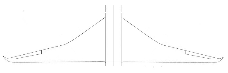
Very Odd!
Looking at the proportions of your latest iteration I would think you could increase the span to 1000 mm without changing anything else..
If the root is strong enough you would be simply extending the outer parts of the wing structure which do not weigh much. It should result in a 30% increase in wing area for maybe only a 10%% increase in the weight of the wing. This sort of thing results in a significant reduction in the wing loading.
A parallel chord wing is relatively simple to make but is far from the ideal structurally. A tapered wing get much closer to providing the strength where it is needed. Deep at the root, thinner towards the tip.
As an example this is the comparison between the root and tip wing sections of my scale 1.5 m span Airbus A350 EDF.
The root is 6 times the depth of the tip so without doing anything clever structurally the wing has remarkable strength for its weight.
We are now so used to seeing swept wing airliners the fact that their wings are so tapered tends to be over looked.
This is what the A350 wing would look like un swept and with the same area as the swept one.
Very Odd!
Thanks: Klipkopwildlife, jon.in.swansea
Please Log in or Create an account to join the conversation.
- jon.in.swansea
-
Topic Author
- Offline
- Elite Member
-
Less
More
- Posts: 766
- Thank you received: 1192
31 May 2022 17:27 #86
by jon.in.swansea
Replied by jon.in.swansea on topic freeCAD and fuselage creation
Interesting idea to extend out the 115mm chord for a longer span - certainly getting more glider-like in aspect ratio. It is certainly stiff enough as is. Just extending...I might need to make the ailerons a bit longer as well? Currently they are ~10% of the wing-half area.
I can imagine keeping the chord the same but going for a slightly deeper spar & rib section near the root. That would be in keeping with my
building skills. I used your Clarke-Y pattern - so is there a problem with increasing the max thickness with a constant chord on some of the ribs so as to have room for a stronger spar?
To create a tapered wing - all aligned along a single (getting less deep as it goes out) spar with set of incrementally smaller ribs would be interesting. I think I might be able to use the 'draft - scale' option in freeCAD to get a suite of ribs.
Would one step the rib sizes (chord and depth) down at a constant rate or something rather more fancy than that? There are, as far as I can see scores of competing ideas about wing taper.
Do you have any photos of your A350 ribs and spar uncovered? -Jon
Thanks: Klipkopwildlife
Please Log in or Create an account to join the conversation.
- Klipkopwildlife
-

- Offline
- Administrator
-

- I'm supposed to be retired!
31 May 2022 17:46 #87
by Klipkopwildlife
Do it now, you may never get another chance
Replied by Klipkopwildlife on topic freeCAD and fuselage creation
I like the way you're going Jon. I don't think you'll need any bigger ailerons, just plug in the extra span pieces outboard.
Do it now, you may never get another chance
Thanks: jon.in.swansea
Please Log in or Create an account to join the conversation.
- Quorneng
-
- Offline
- Forum Master
-
Less
More
- Posts: 9436
- Thank you received: 19043
31 May 2022 22:58 - 31 May 2022 23:01 #88
by Quorneng
Replied by Quorneng on topic freeCAD and fuselage creation
jon
You have to remember my A350 used true scale wing sections. Not the most efficient thing at small sizes but it is very thick at the root. In a really light weight structure sometimes gaining strength is more important than obtaining the most efficient lift.
This shows the substantial wing thickness out to the EDF pylons.

The single spar is a balsa/Depron/balsa structure. The green bit at the trailing edge is just a support to keep the ribs at the correct levels.
Note the 2 mm thick balsa spar flange goes over the printed ribs. The front and back 2 mm foam wing skins are simply butt glued to the balsa.
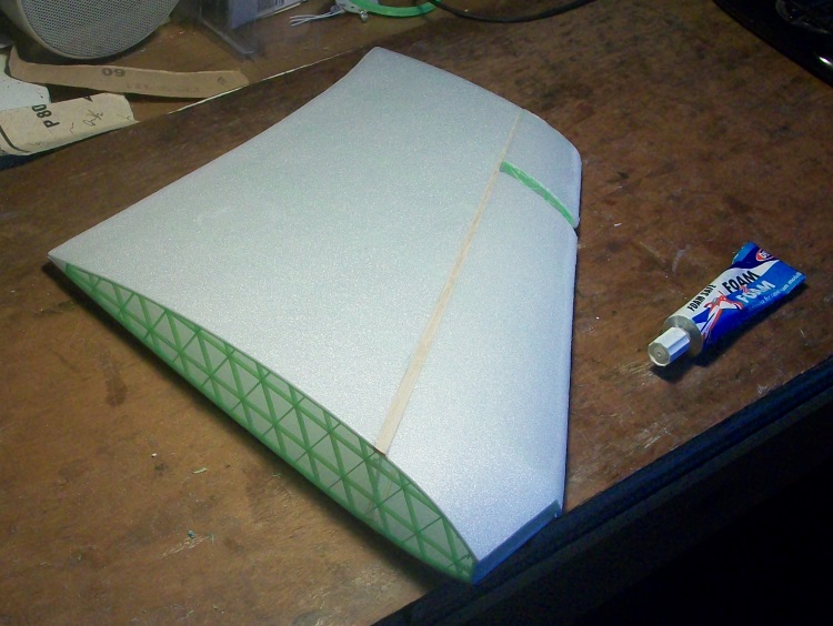 .
The end result is the spar is flush with the outer surface of the wing giving the spar the maximum possible depth and stiffness for the minimum weight.
As the wing is so highly tapered I judged the 2 mm Depron wing skins on the outer panels would be strong enough without any spar at all.:ohmy:

Just two Depron spacers to give the required wing section when the top and bottom skins were pulled over them and glued in place. With a bit of 'adjustment' It can create a near scale semi symmetrical scale wing section..
Finally as the outer wings have no spar they are simply glued directly onto the inner wing. :woohoo: In fact an accurately prepared foam to foam but joint is as strong as the foam itself and is very light.
The completed LH wing.

I hope this helps.
To be fair I had built quite a few lightweight foam skin planes of various sizes to get a pretty good idea of what was likely to work before the A350 however being so obsessive about weight does mean such planes can fly very nicely but the down side is they crash in a scale manner too.
You have to remember my A350 used true scale wing sections. Not the most efficient thing at small sizes but it is very thick at the root. In a really light weight structure sometimes gaining strength is more important than obtaining the most efficient lift.
This shows the substantial wing thickness out to the EDF pylons.
The single spar is a balsa/Depron/balsa structure. The green bit at the trailing edge is just a support to keep the ribs at the correct levels.
Note the 2 mm thick balsa spar flange goes over the printed ribs. The front and back 2 mm foam wing skins are simply butt glued to the balsa.
The end result is the spar is flush with the outer surface of the wing giving the spar the maximum possible depth and stiffness for the minimum weight.
As the wing is so highly tapered I judged the 2 mm Depron wing skins on the outer panels would be strong enough without any spar at all.:ohmy:
Just two Depron spacers to give the required wing section when the top and bottom skins were pulled over them and glued in place. With a bit of 'adjustment' It can create a near scale semi symmetrical scale wing section..
Finally as the outer wings have no spar they are simply glued directly onto the inner wing. :woohoo: In fact an accurately prepared foam to foam but joint is as strong as the foam itself and is very light.
The completed LH wing.
I hope this helps.
To be fair I had built quite a few lightweight foam skin planes of various sizes to get a pretty good idea of what was likely to work before the A350 however being so obsessive about weight does mean such planes can fly very nicely but the down side is they crash in a scale manner too.
Last edit: 31 May 2022 23:01 by Quorneng.
Thanks: Klipkopwildlife, jon.in.swansea
Please Log in or Create an account to join the conversation.
- Klipkopwildlife
-
- Offline
- Administrator
-
- I'm supposed to be retired!
02 Jun 2022 08:58 #89
by Klipkopwildlife
Do it now, you may never get another chance
Replied by Klipkopwildlife on topic freeCAD and fuselage creation
Hi Jon, extensive research
Here
seems to show that the Clark Y can be slimmed down to very thin or up sized to 35% with very little loss in efficiency, obviously the lift/drag goes sky high for the thicker sections (there's no free lunch)
The original Clark Y foil was just under 12% thick (11.7), I see no reason why you can't go to a much thicker section with very little increase in weight that would be much stronger and give massively more lift, = flies slower.
The original Clark Y foil was just under 12% thick (11.7), I see no reason why you can't go to a much thicker section with very little increase in weight that would be much stronger and give massively more lift, = flies slower.
Do it now, you may never get another chance
Thanks: jon.in.swansea
Please Log in or Create an account to join the conversation.
- Quorneng
-
- Offline
- Forum Master
-
Less
More
- Posts: 9436
- Thank you received: 19043
02 Jun 2022 15:09 - 02 Jun 2022 15:11 #90
by Quorneng
Replied by Quorneng on topic freeCAD and fuselage creation
Yes
But more drag means the same power to fly slower as flying faster with a thinner wing section.
One aspect of all model flying is the viscosity of air or rather the thickness of the boundary layer of slow moving air that 'sticks' to the surface. The problem is the boundary layer thickness is the same regardless of size.
This means on a model the boundary layer makes a wing section behave aerodynamically rather thicker than it is.
The smaller the model the thinner the wing has to be to achieve anything like the the full size performance.
Just saying.
Last edit: 02 Jun 2022 15:11 by Quorneng.
Thanks: Klipkopwildlife, jon.in.swansea
Please Log in or Create an account to join the conversation.
Time to create page: 3.180 seconds