
- Posts: 9436
- Thank you received: 19043
Printing with Light Weight PLA
- Quorneng
-
 Topic Author
- Offline
- Forum Master
-

Less
More
13 Dec 2022 00:16 #1
by Quorneng
Printing with Light Weight PLA was created by Quorneng
My J head high temperature print head has arrived.
Very neat with a shrouded cooling fan onto a heavily finned body and a silicone 'sock" for the heater body.

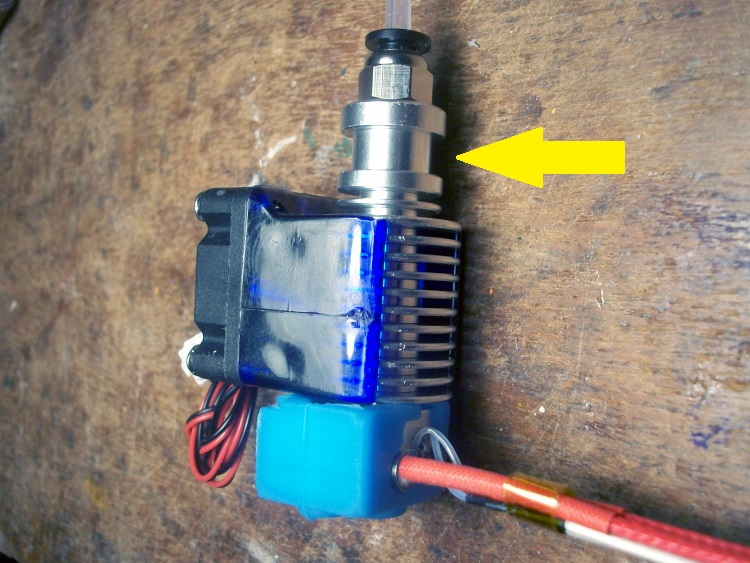
The Ebay advert listed it suitable for an Anet A8.but just at the moment I cant see how it is mounted at least within the original carriage body parts. I presume it is intended to be secured by the indicated recessed area at top of the feed tube.
Actually working out how to fit it, running the power and thermistor wires through the cable trays is a job for another day.
Very neat with a shrouded cooling fan onto a heavily finned body and a silicone 'sock" for the heater body.
The Ebay advert listed it suitable for an Anet A8.but just at the moment I cant see how it is mounted at least within the original carriage body parts. I presume it is intended to be secured by the indicated recessed area at top of the feed tube.
Actually working out how to fit it, running the power and thermistor wires through the cable trays is a job for another day.
Thanks: Klipkopwildlife
Please Log in or Create an account to join the conversation.
- Klipkopwildlife
-

- Offline
- Administrator
-

- I'm supposed to be retired!
15 Dec 2022 17:24 #2
by Klipkopwildlife
Do it now, you may never get another chance
Replied by Klipkopwildlife on topic Fitting a new hot end
Simon has a new hot end. No sexual references please![badass]
Do it now, you may never get another chance
Please Log in or Create an account to join the conversation.
- Klipkopwildlife
-
- Offline
- Administrator
-
- I'm supposed to be retired!
15 Dec 2022 17:29 #3
by Klipkopwildlife
Do it now, you may never get another chance
Replied by Klipkopwildlife on topic Printing with Light Weight PLA
My first comment is, you'll have to use your existing Thermistor. I will have to find a way to get new Firmware to you. You will not get any sense out of your control software using the new one.
Do it now, you may never get another chance
Please Log in or Create an account to join the conversation.
- Quorneng
-
Topic Author
- Offline
- Forum Master
-
Less
More
- Posts: 9436
- Thank you received: 19043
15 Dec 2022 19:07 #4
by Quorneng
Replied by Quorneng on topic Printing with Light Weight PLA
A good heads up. I had not thought of that.
No problem transferring the existing thermistor. In fact it would be easier as it would mean I wouldn't have to run the new thermistor wires.
No problem transferring the existing thermistor. In fact it would be easier as it would mean I wouldn't have to run the new thermistor wires.
Please Log in or Create an account to join the conversation.
- Klipkopwildlife
-
- Offline
- Administrator
-
- I'm supposed to be retired!
16 Dec 2022 06:59 - 16 Dec 2022 09:24 #5
by Klipkopwildlife
Do it now, you may never get another chance
Replied by Klipkopwildlife on topic Printing with Light Weight PLA
The v6 is designed to hang from the top so there is no contact in the hot areas. This is the thingyverse carriage I downloaded.
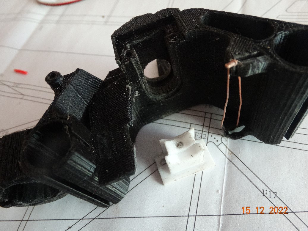
And with the hot end mounted.

PLA tends to move over time, the rails that attach the toothed drive belt was a particular problem. As was the actual mounting when heat got to the top of the hot end if there was a power outage.
I decided to re-configure the original aluminium carriage
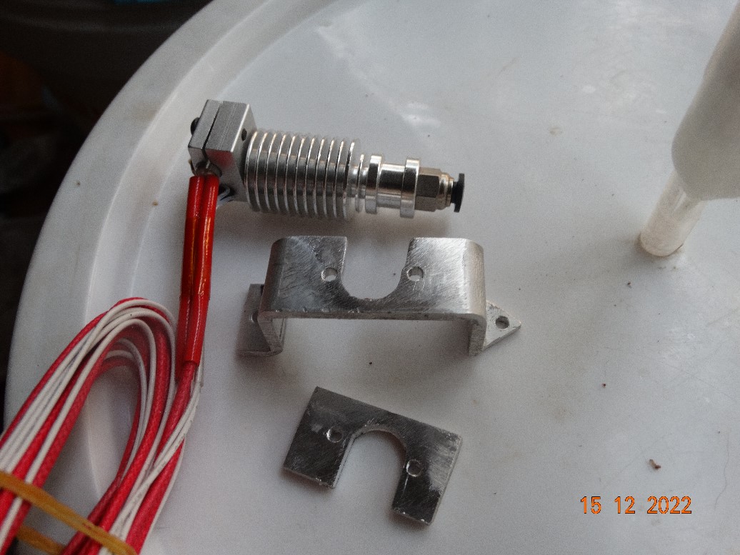
These are the parts. I had to cut through the carriage to make the hot end fit.

And ready to go.
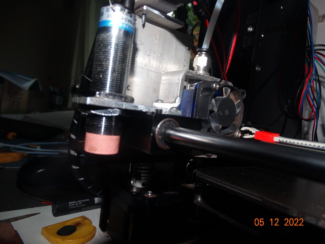
And with the hot end mounted.
PLA tends to move over time, the rails that attach the toothed drive belt was a particular problem. As was the actual mounting when heat got to the top of the hot end if there was a power outage.
I decided to re-configure the original aluminium carriage
These are the parts. I had to cut through the carriage to make the hot end fit.
And ready to go.
Do it now, you may never get another chance
Last edit: 16 Dec 2022 09:24 by Klipkopwildlife.
Thanks: Quorneng
Please Log in or Create an account to join the conversation.
- Quorneng
-
Topic Author
- Offline
- Forum Master
-
Less
More
- Posts: 9436
- Thank you received: 19043
16 Dec 2022 17:14 #6
by Quorneng
Replied by Quorneng on topic Printing with Light Weight PLA
Klippy
Thanks that makes it clear.
I fully expect I shall have to do the same sort of thing.
Thanks that makes it clear.
I fully expect I shall have to do the same sort of thing.
Thanks: Klipkopwildlife
Please Log in or Create an account to join the conversation.
- jon.in.swansea
-

- Offline
- Elite Member
-

Less
More
- Posts: 766
- Thank you received: 1192
19 Feb 2023 13:34 #7
by jon.in.swansea
Replied by jon.in.swansea on topic Printing with Light Weight PLA
Pardon my being away for quite a while - not having a boiler or hot water for 6 weeks is a distraction...Seems like a good thread to share my explorations of LW-PLA.

I had had a spool of PolyLight 1.0 LW-PLA for some time and finally decided to give it a try.
I did lots of looking at YouTube and gathering information.
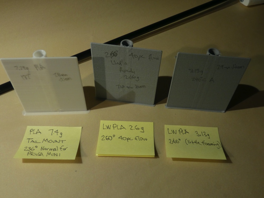
I started with a print of an existing SLT of a boom to tail connector. It seemed to follow the patterns that I had seen. It was certainly less stiff and with the expansion from the foaming it was clear that critical dimensions - like to a boom or a spar one would need to adapt the CAD dimensions.

I also did a test on one of my sets of ribs - what a mess. Retractions are an issue for ribs so I decided to go back and do the usual tests to find out the settings needed in the slicer as well as FreeCAD and on the printer itself to get this new kid on the block to live up to its claimed performance.


I did cubes with normal 0.5mm walls and 1mm walls at different settings.
I went back to the original Clark-Y sketch and re-worked it for a carbon fibre spar. Printed spars on a Prusa Mini are just lots of trouble so I wanted to explore. Learned early on to leave the beastie on the bed until it was cool otherwise one gets a pretzel.

The minimal infil I used in PLA ribs proved to be mostly useless in LW-PLA. Since printing with no top layer makes it difficult to enforce braces I added some very thin blocks just shy of the outer flange and subtracted those to force the creation of some braces.

Two perimeters and 2 base layers got a rib less than 1g. Still somewhat squishy. Could I do better?
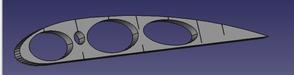
I did some more looking and found lots of designs which put the 'subtracted slices' at the perimeter. Tried that. The extrusions did join. Nice to know. Still lots of retractions.

So I went back to YouTube and looked at some example wings and finally figured out the further tweaks needed to allow for a vase mode print - e.g. one with no retractions after the base layers had been laid down.

From ~3g in standard PLA to 0.8g in LW-PLA I think I might be on my way to dropping some weight from my models and getting closer to a nice slow park flyer.
This is a terse summary. I documented more of the steps and show what it actually looks like when printing in a YouTube video. It is ~6 minutes which some Aeromodeller's will not be so willing to sit through but it does go into the rules I ended up with for transitioning CAD entities to get to something that can be vase printed. Enjoy.
I had had a spool of PolyLight 1.0 LW-PLA for some time and finally decided to give it a try.
I did lots of looking at YouTube and gathering information.
I started with a print of an existing SLT of a boom to tail connector. It seemed to follow the patterns that I had seen. It was certainly less stiff and with the expansion from the foaming it was clear that critical dimensions - like to a boom or a spar one would need to adapt the CAD dimensions.
I also did a test on one of my sets of ribs - what a mess. Retractions are an issue for ribs so I decided to go back and do the usual tests to find out the settings needed in the slicer as well as FreeCAD and on the printer itself to get this new kid on the block to live up to its claimed performance.
I did cubes with normal 0.5mm walls and 1mm walls at different settings.
I went back to the original Clark-Y sketch and re-worked it for a carbon fibre spar. Printed spars on a Prusa Mini are just lots of trouble so I wanted to explore. Learned early on to leave the beastie on the bed until it was cool otherwise one gets a pretzel.
The minimal infil I used in PLA ribs proved to be mostly useless in LW-PLA. Since printing with no top layer makes it difficult to enforce braces I added some very thin blocks just shy of the outer flange and subtracted those to force the creation of some braces.
Two perimeters and 2 base layers got a rib less than 1g. Still somewhat squishy. Could I do better?
I did some more looking and found lots of designs which put the 'subtracted slices' at the perimeter. Tried that. The extrusions did join. Nice to know. Still lots of retractions.
So I went back to YouTube and looked at some example wings and finally figured out the further tweaks needed to allow for a vase mode print - e.g. one with no retractions after the base layers had been laid down.
From ~3g in standard PLA to 0.8g in LW-PLA I think I might be on my way to dropping some weight from my models and getting closer to a nice slow park flyer.
This is a terse summary. I documented more of the steps and show what it actually looks like when printing in a YouTube video. It is ~6 minutes which some Aeromodeller's will not be so willing to sit through but it does go into the rules I ended up with for transitioning CAD entities to get to something that can be vase printed. Enjoy.
Thanks: Klipkopwildlife, Quorneng
Please Log in or Create an account to join the conversation.
- Quorneng
-
Topic Author
- Offline
- Forum Master
-
Less
More
- Posts: 9436
- Thank you received: 19043
19 Feb 2023 16:35 - 19 Feb 2023 16:37 #8
by Quorneng
Replied by Quorneng on topic Printing with Light Weight PLA
jon
That is a very interesting set of experiments in LW-PLA printing..
Getting lots of 'tails' from each nozzle position change appears to be a generic problem with LW-PLA requiring a substantial retract to minimise it. From what the situation is even worse in that the sort of retract required tends to result in nozzle clogging.
In a complete hollow item typical of a printed part for plane any tails are usually internal so tend to be accepted as a 'feature' of LW-PLA printing.
The only way I have found so far to achieve a perfect LW-PLA print is to have no position changes at all! In other words 'vase' or continuous printing. Using this process does of course limit the shape of what can be printed but it does work very well for EDF ducts.
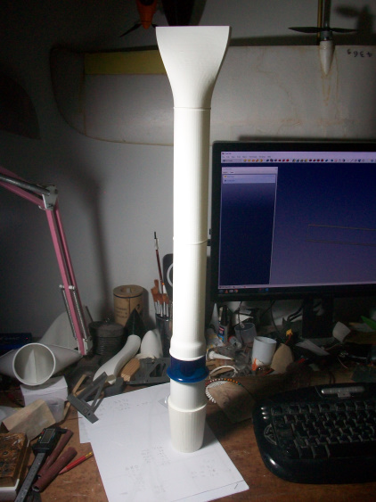
Each of the five sections are created individually as a single wall 'vase' print using a 0.4 mm nozzle at 220 degrees with a 50% flow to give an actual wall thickness of 0.9 mm. The final weight is just over half that of a non foamed PLA print. Overlapping joints are included in the design so each part can be simply glued together which LW-PLA does very well.
I have not so far tried to LW-PLA any of my wing rib or fuselage former designs.
Your wing rib experiments do give me some ideas to try.
That is a very interesting set of experiments in LW-PLA printing..
Getting lots of 'tails' from each nozzle position change appears to be a generic problem with LW-PLA requiring a substantial retract to minimise it. From what the situation is even worse in that the sort of retract required tends to result in nozzle clogging.
In a complete hollow item typical of a printed part for plane any tails are usually internal so tend to be accepted as a 'feature' of LW-PLA printing.
The only way I have found so far to achieve a perfect LW-PLA print is to have no position changes at all! In other words 'vase' or continuous printing. Using this process does of course limit the shape of what can be printed but it does work very well for EDF ducts.
Each of the five sections are created individually as a single wall 'vase' print using a 0.4 mm nozzle at 220 degrees with a 50% flow to give an actual wall thickness of 0.9 mm. The final weight is just over half that of a non foamed PLA print. Overlapping joints are included in the design so each part can be simply glued together which LW-PLA does very well.
I have not so far tried to LW-PLA any of my wing rib or fuselage former designs.
Your wing rib experiments do give me some ideas to try.
Last edit: 19 Feb 2023 16:37 by Quorneng.
Thanks: Klipkopwildlife, jon.in.swansea
Please Log in or Create an account to join the conversation.
- jon.in.swansea
-
- Offline
- Elite Member
-
Less
More
- Posts: 766
- Thank you received: 1192
20 Feb 2023 09:28 #9
by jon.in.swansea
Replied by jon.in.swansea on topic Printing with Light Weight PLA
Thanks for the comments.... I have done some exploring and think I have begun to crack the wing-vase-mode pattern. I was thinking how to loose weight at the ends of the wings where I tended to have a printed set of ribs setup for the aileron to fit within. Then I thought - why not try to print it not as ribs and spars but as a vase.
I took a Clark-Y rib trace sketch and scaled it and raised on. Did a 'loft' and then subtracted a cylinder for the spar and then a series of very thin slots at the perimeter 'almost' meeting in the centre. I found LWPLA is rubbish at overhangs so I ended up using a wedge shape in FreeCAD to make a 'cut-out' for an aileron servo on the bottom surface so there is enough slope in that cut-out upper and lower faces.
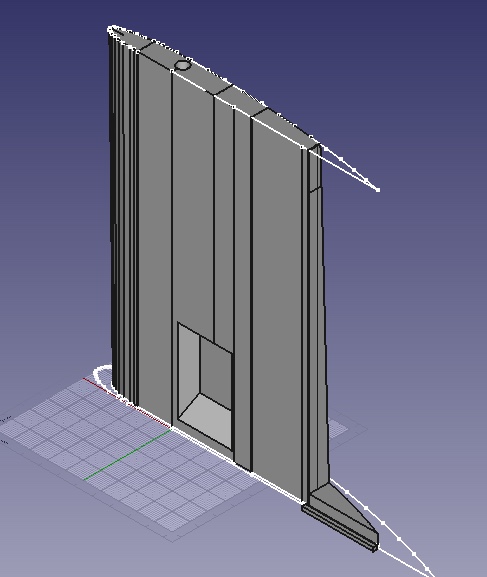
It is printing now....
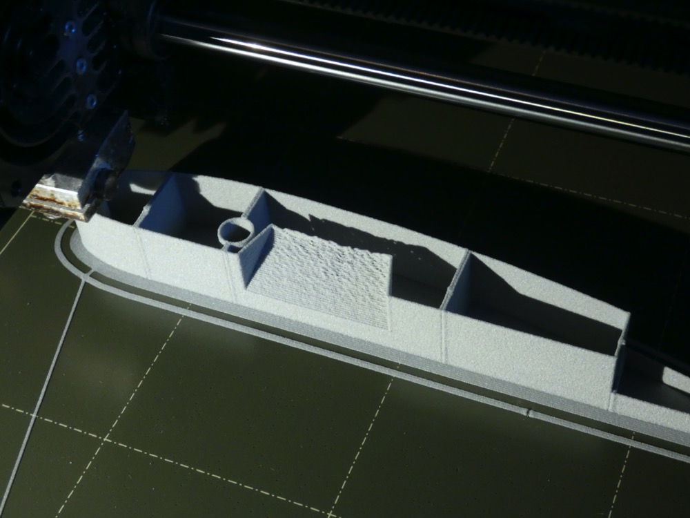
I am seriously chuffed at this discovery. I suspect I might keep the rest of the wing as ribs and foam but for the fiddly bits at the wing tip this might be workable.
I took a Clark-Y rib trace sketch and scaled it and raised on. Did a 'loft' and then subtracted a cylinder for the spar and then a series of very thin slots at the perimeter 'almost' meeting in the centre. I found LWPLA is rubbish at overhangs so I ended up using a wedge shape in FreeCAD to make a 'cut-out' for an aileron servo on the bottom surface so there is enough slope in that cut-out upper and lower faces.
It is printing now....
I am seriously chuffed at this discovery. I suspect I might keep the rest of the wing as ribs and foam but for the fiddly bits at the wing tip this might be workable.
Thanks: Klipkopwildlife, Flytilbroke, Quorneng
Please Log in or Create an account to join the conversation.
- jon.in.swansea
-
- Offline
- Elite Member
-
Less
More
- Posts: 766
- Thank you received: 1192
20 Feb 2023 09:33 #10
by jon.in.swansea
Replied by jon.in.swansea on topic Printing with Light Weight PLA
And here is the slicer view of what I am printing. I will cap off the top with some normal PLA (vase mode and supports don't mix).
I might need another couple of internal braces - depends on how squishy the skin of the wing is....

I might need another couple of internal braces - depends on how squishy the skin of the wing is....
Thanks: Klipkopwildlife, Quorneng
Please Log in or Create an account to join the conversation.
- Quorneng
-
Topic Author
- Offline
- Forum Master
-
Less
More
- Posts: 9436
- Thank you received: 19043
20 Feb 2023 11:46 #11
by Quorneng
Replied by Quorneng on topic Printing with Light Weight PLA
jon
You are getting seriously clever at persuading CAD to do what you want!
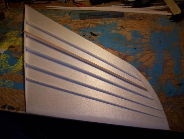
I do have a concern at a wing with just spars instead of ribs.
A conventional rib acts is a 'beam' to ensure the wing section does not distort and change shape. A wing with just spars is much freer to do that as shown in this rather exaggerated diagram.

I have used rib less wing structures but they have relied on thick stiff top and bottom wing skins to resist any change in wing section.
Part of the problem with LW-PLA is its flexibility compared to ordinary PLA.
Where the part has more than adequate stiffness by design then substituting LW-PLA can work well giving a useful weight saving but where stiffness of PLA is being used a LW-PLA substitution is not so good.
It will be interesting to see if 'flexibility' rather than simple wing bending will be significant in your design.
You are getting seriously clever at persuading CAD to do what you want!
I do have a concern at a wing with just spars instead of ribs.
A conventional rib acts is a 'beam' to ensure the wing section does not distort and change shape. A wing with just spars is much freer to do that as shown in this rather exaggerated diagram.
I have used rib less wing structures but they have relied on thick stiff top and bottom wing skins to resist any change in wing section.
Part of the problem with LW-PLA is its flexibility compared to ordinary PLA.
Where the part has more than adequate stiffness by design then substituting LW-PLA can work well giving a useful weight saving but where stiffness of PLA is being used a LW-PLA substitution is not so good.
It will be interesting to see if 'flexibility' rather than simple wing bending will be significant in your design.
Thanks: Klipkopwildlife, jon.in.swansea
Please Log in or Create an account to join the conversation.
- jon.in.swansea
-
- Offline
- Elite Member
-
Less
More
- Posts: 766
- Thank you received: 1192
20 Feb 2023 18:57 #12
by jon.in.swansea
Replied by jon.in.swansea on topic Printing with Light Weight PLA
Good observation. I just pulled the print off the printer platform. For a 155mm chord and 172 length it came out at 14g. I suspect this is less weight than the PLA ribs and spar I used i the past - must look up my notes.... It seems to resist twist.

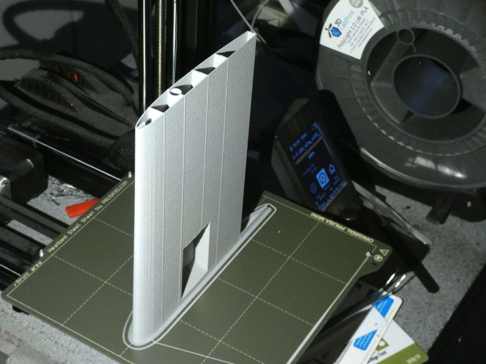
I am a bit more worried about gluing it to the inner section of wing - I just got some ZAP-O foam safe CA and did a small bonding test with the LW-PLA. ZAP seems popular with glider folk who are also concerned with weight. Anyone have prior experience of ZAP-O?
Even if that bond proves strong I worry that an adjacent section of LW-PLA wing skin - say 5-10mm away from the bond will not have sufficient tension or compressive strength. Then again perhaps LW-PLA just bends a bit like a willow and there is little to worry about?
I could add in a couple of angled bracing spars to complement the existing printed spars and see what happens. Or would it be better to brace each of the existing printed spars?
The other would be to design it to use two CF spars (perhaps the trailing spar being a bit smaller in diameter)? That would reduce my worry about tension faults at the cost of ~10g of CF.
I suppose one test would be to print several sections glue them without the CF spar and see what kind of weight they will carry. And then do it with a CF spar and see how much that adds. I suspect the 1kg in the centre of a 1m span would break the back of a LW-PLA wing.
And yet another question....
My wall thickness with 260C is 0.8 from a 0.4mm nozzle. I might try some test cells again with a bit higher temperature and see if that can get me up to 0.9 or even 1mm. Is thicker stronger because of the thickness or does the failure point become a lower compressive and tension strength at the higher foaming??
Exciting days....
Thanks: Klipkopwildlife
Please Log in or Create an account to join the conversation.
- Klipkopwildlife
-
- Offline
- Administrator
-
- I'm supposed to be retired!
21 Feb 2023 07:14 - 21 Feb 2023 07:14 #13
by Klipkopwildlife
Do it now, you may never get another chance
Replied by Klipkopwildlife on topic Printing with Light Weight PLA
Hi Jon, great stuff, I notice that Plane Print get a larger chord by printing across the diagonal. Is this possible with your method of slicing?
Do it now, you may never get another chance
Last edit: 21 Feb 2023 07:14 by Klipkopwildlife.
Please Log in or Create an account to join the conversation.
- jon.in.swansea
-
- Offline
- Elite Member
-
Less
More
- Posts: 766
- Thank you received: 1192
21 Feb 2023 08:12 #14
by jon.in.swansea
Replied by jon.in.swansea on topic Printing with Light Weight PLA
Printing on the diagonal of the bed. Yes, I use that for many parts to get past the 180mm limit of the bed on a Prusa Min. That would give 230-240mm depending on the thickness. Like the spars I print. Just a few clicks in the slicer to rotate the model on the build plate.
That does not address the Z height limitations. Speaking of which - vase mode yields an open top. Not much surface area to glue to match the open top to the adjacent wing section. Designing a taper so that one piece can overlap the next for beasties this complex is not yet in my skill set.
That does not address the Z height limitations. Speaking of which - vase mode yields an open top. Not much surface area to glue to match the open top to the adjacent wing section. Designing a taper so that one piece can overlap the next for beasties this complex is not yet in my skill set.
Thanks: Klipkopwildlife
Please Log in or Create an account to join the conversation.
- Quorneng
-
Topic Author
- Offline
- Forum Master
-
Less
More
- Posts: 9436
- Thank you received: 19043
21 Feb 2023 11:09 - 21 Feb 2023 11:14 #15
by Quorneng
Replied by Quorneng on topic Printing with Light Weight PLA
Having used printed PLA wing ribs and formers quite successfully with a sheet Depron skin I wondered if LW-PLA could be substituted. My AN 124 is by far the largest and heaviest I have built using this technique. I wish now that I had kept a tally of the weight of all the printed parts so the significance of any LW-PLA weight saving could be determined. Off the top of my head I suspect the PLA parts of the AN 124, which also included the engine nacelles and pylons may well have contributed nearly 25% of its 1560 g (55 oz) all up weight. So I decided to do some comparative prints of part of one of the fuselage formers.
A warren braced beam that created the main fuselage floor. There were 15 of them of 3 slightly different shapes.
First I printed one out in PLA as used in the plane.
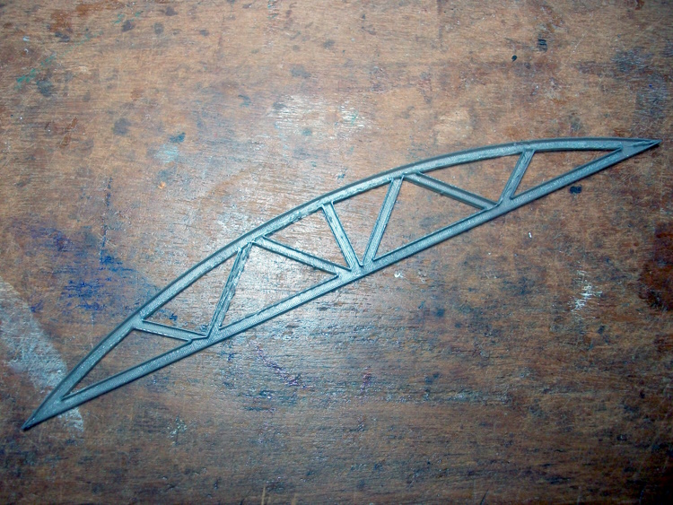
By experiment at the time of building I had determined that a 3x3 mm "U" channel section gave the best compromise of stiffness, weight and printing time.
It weighs 2.07 g.
Next step was to simply replicate this using LW-PLA.

It weighs only 0.97g but is much more flexible than the PLA original and would probably be unusable.
Obviously the LW-PLA version would have to be stiffer. Adding a top layer would convert the "U" channel into a box section.
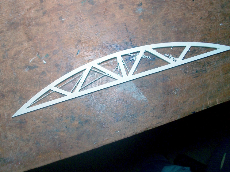
Note the tails left by the LW=PLA. Being softer than PLA they are easy to cut off.
Much improved stiffness but the weight increased to 1.44 g
I noted that the greater wall thickness of LW-PLA , 0.9 rather than 0.4, in effect increased the section to 4 mm wide.
It is worth noting that CURA automatically compensates for this extra wall thickness as the outside dimensions of the PLA and LW=PLA parts are identical.
It would improve the stiffness stiff further is the box was 4x4 mm.
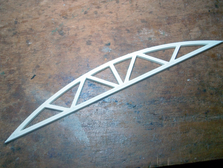
This now has a comparable stiffness to the PLA "U" channel and at 1.68 g also gives a useful 20% weight saving but it took nearly 2.5 times longer to print.

I expect that print time could be improved but LW-PLA printing does seem to favour slower print speeds.
Overall this test does rather confirm my earlier observation that where the strength and stiffness of PLA is specifically being used the substitution of LW-PLA has a very limited advantage.
I note that in jon's wing section by using a carbon spar the LW-PLA is not carrying the primary bending load so LW-PLA may well give a useful weight saving benefit.
Joining an 'open topped' wing section?
Now that is a tricky problem!
A warren braced beam that created the main fuselage floor. There were 15 of them of 3 slightly different shapes.
First I printed one out in PLA as used in the plane.
By experiment at the time of building I had determined that a 3x3 mm "U" channel section gave the best compromise of stiffness, weight and printing time.
It weighs 2.07 g.
Next step was to simply replicate this using LW-PLA.
It weighs only 0.97g but is much more flexible than the PLA original and would probably be unusable.
Obviously the LW-PLA version would have to be stiffer. Adding a top layer would convert the "U" channel into a box section.
Note the tails left by the LW=PLA. Being softer than PLA they are easy to cut off.
Much improved stiffness but the weight increased to 1.44 g
I noted that the greater wall thickness of LW-PLA , 0.9 rather than 0.4, in effect increased the section to 4 mm wide.
It is worth noting that CURA automatically compensates for this extra wall thickness as the outside dimensions of the PLA and LW=PLA parts are identical.
It would improve the stiffness stiff further is the box was 4x4 mm.
This now has a comparable stiffness to the PLA "U" channel and at 1.68 g also gives a useful 20% weight saving but it took nearly 2.5 times longer to print.
I expect that print time could be improved but LW-PLA printing does seem to favour slower print speeds.
Overall this test does rather confirm my earlier observation that where the strength and stiffness of PLA is specifically being used the substitution of LW-PLA has a very limited advantage.
I note that in jon's wing section by using a carbon spar the LW-PLA is not carrying the primary bending load so LW-PLA may well give a useful weight saving benefit.
Joining an 'open topped' wing section?
Now that is a tricky problem!
Last edit: 21 Feb 2023 11:14 by Quorneng.
Thanks: Klipkopwildlife, jon.in.swansea
Please Log in or Create an account to join the conversation.
Time to create page: 1.008 seconds