
- Posts: 766
- Thank you received: 1192
Printing with Light Weight PLA
- jon.in.swansea
-

- Offline
- Elite Member
-

Less
More
26 Feb 2023 16:51 #31
by jon.in.swansea
Replied by jon.in.swansea on topic Printing with Light Weight PLA
Goodness the aileron did print ok flat!
How do you imagine pivoting such an aileron within that kind of pocket? In the past I had designed in a shaft into the aileron that I could pin a length of bamboo rod into.
How do you imagine pivoting such an aileron within that kind of pocket? In the past I had designed in a shaft into the aileron that I could pin a length of bamboo rod into.
Please Log in or Create an account to join the conversation.
- Klipkopwildlife
-

- Away
- Administrator
-

- I'm supposed to be retired!
26 Feb 2023 17:17 #32
by Klipkopwildlife
Do it now, you may never get another chance
Replied by Klipkopwildlife on topic Printing with Light Weight PLA
Hinges printed in TPU are nothing short of amazing, I'll make sure you go back with some Jon.
Do it now, you may never get another chance
Thanks: jon.in.swansea
Please Log in or Create an account to join the conversation.
- jon.in.swansea
-
- Offline
- Elite Member
-
Less
More
- Posts: 766
- Thank you received: 1192
27 Feb 2023 08:58 #33
by jon.in.swansea
Replied by jon.in.swansea on topic Printing with Light Weight PLA
I ran a couple of iterations of the leading edge printed flat along the spar....
For a 220mm long print the vase mode came in at 10.1g it is sort of stiff. The top was somewhat ragged and would require some post-processing to infil. Don't know what would work well for that. It would probably take a 'lite knock' in a crash but I suspect that the 3 intermediate ribs at 50mm centres would really need to be 4-5 ribs.
I then re-worked the CAD to remove the vase ribs and create a solid hollow body and then printed it with 5% gyroid infil, 2 base layers, 1 top layer. That comes in at 13.4g. It is way more stiff in terms of bending as well as surface crushing.
I then re-tried it with 4% gyroid and everything else the same and it came in at 11.3g. It is still nicely stiff to torsion and crush and at 1.2g more than the vase mode I think that is 'simple enough'. Dare I try a 3%? I suspect I might have to go to 2 top layers to maintain the shape of the leading edge.
Thanks: Klipkopwildlife
Please Log in or Create an account to join the conversation.
- Quorneng
-
 Topic Author
- Offline
- Forum Master
-

Less
More
- Posts: 9436
- Thank you received: 19043
27 Feb 2023 10:26 - 27 Feb 2023 10:27 #34
by Quorneng
Replied by Quorneng on topic Printing with Light Weight PLA
jon
That rather matches what I had found.
I would agree that 2 top layers is likely to be required to maintain the shape of almost any 'closed' top..
Obviously as with any fill the lower the % the less the skin is supported but uniquely with gyroid the radius of the internal fill structure also decreases thus additionally reducing its stiffness.
In addition unlike the other fills you have no control over its position within the body so the unsupported areas can end up bigger than might otherwise be possible.
This shows the likely differences between a 5% & 3% gyroid fill.
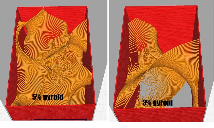
Indeed given that in some areas the lines of filament are relatively a long way apart it is surprising gyroid is as rigid as it is however the thick foam bead with LW-PLA likely favours it as a fill.
That rather matches what I had found.
I would agree that 2 top layers is likely to be required to maintain the shape of almost any 'closed' top..
Obviously as with any fill the lower the % the less the skin is supported but uniquely with gyroid the radius of the internal fill structure also decreases thus additionally reducing its stiffness.
In addition unlike the other fills you have no control over its position within the body so the unsupported areas can end up bigger than might otherwise be possible.
This shows the likely differences between a 5% & 3% gyroid fill.
Indeed given that in some areas the lines of filament are relatively a long way apart it is surprising gyroid is as rigid as it is however the thick foam bead with LW-PLA likely favours it as a fill.
Last edit: 27 Feb 2023 10:27 by Quorneng.
Thanks: Klipkopwildlife, jon.in.swansea
Please Log in or Create an account to join the conversation.
- Quorneng
-
Topic Author
- Offline
- Forum Master
-
Less
More
- Posts: 9436
- Thank you received: 19043
27 Feb 2023 14:41 - 27 Feb 2023 14:43 #35
by Quorneng
Replied by Quorneng on topic Printing with Light Weight PLA
jon
You asked about how to hinge the matching wing and aileron.
I judged that the wing and aileron were rigid enough for a lightweight to only need hinges on each end.
Just simple bits of acetate glued on and a pair of pins!
Pretty free moving too!
You asked about how to hinge the matching wing and aileron.
I judged that the wing and aileron were rigid enough for a lightweight to only need hinges on each end.
Just simple bits of acetate glued on and a pair of pins!
Pretty free moving too!
Last edit: 27 Feb 2023 14:43 by Quorneng.
Thanks: Klipkopwildlife, jon.in.swansea
Please Log in or Create an account to join the conversation.
- jon.in.swansea
-
- Offline
- Elite Member
-
Less
More
- Posts: 766
- Thank you received: 1192
28 Feb 2023 17:06 #36
by jon.in.swansea
Replied by jon.in.swansea on topic Printing with Light Weight PLA
I would not have thought about that kind of hinge. And it is tough enough to take the odd tip-of-the-wing-in-the-grass shake?
Please Log in or Create an account to join the conversation.
- Quorneng
-
Topic Author
- Offline
- Forum Master
-
Less
More
- Posts: 9436
- Thank you received: 19043
28 Feb 2023 17:21 #37
by Quorneng
Replied by Quorneng on topic Printing with Light Weight PLA
jon
It certainly feels quite adequate but I wont know for sure till I try it.
I suspect in the completed wing there would be a shaped 'tip piece' that would help protect the aileron a bit.
The last thing i wat to try is to 'loft' the wing section to produce a tapered wing.
It certainly feels quite adequate but I wont know for sure till I try it.
I suspect in the completed wing there would be a shaped 'tip piece' that would help protect the aileron a bit.
The last thing i wat to try is to 'loft' the wing section to produce a tapered wing.
Thanks: jon.in.swansea
Please Log in or Create an account to join the conversation.
- jon.in.swansea
-
- Offline
- Elite Member
-
Less
More
- Posts: 766
- Thank you received: 1192
28 Feb 2023 17:51 #38
by jon.in.swansea
Replied by jon.in.swansea on topic Printing with Light Weight PLA
I am just now exploring lofting a tapered wing - thickness along the length (from 11mm to 30mm as well as the cord from 140mm to 180mm over the half-wing span of 500mm.
I found a work-flow that allowed me to scale the underlying sketch of the rib and then adjust the cut-outs for vase mode LW-PLA ribs.
And the last 220mm end of the wing will be printed in LW-PLA and the whole lot brought together with a CF spar.
I found heat bending foam for thin wing section to be problematic (tight radius at the leading edge). The print hopefully will take care of that.
I am busy printing - once I get all the ribs and the wing and aileron I will weigh them up - I hope for quite a bit of weight saving.
Thanks: Klipkopwildlife, Quorneng
Please Log in or Create an account to join the conversation.
- jon.in.swansea
-
- Offline
- Elite Member
-
Less
More
- Posts: 766
- Thank you received: 1192
28 Feb 2023 17:56 #39
by jon.in.swansea
Replied by jon.in.swansea on topic Printing with Light Weight PLA
I printed a 220mm length of trailing edge wing with 3% gyroid infil and it actually worked well. Still stiff. Saved 2+g over the 4% version.
Stiffer then just using vase-mode ribs but it does come at a weight cost. Vase mode vertical wing might work better with more ribs - say 20-25mm between rather than ~40mm.
Stiffer then just using vase-mode ribs but it does come at a weight cost. Vase mode vertical wing might work better with more ribs - say 20-25mm between rather than ~40mm.
Thanks: Klipkopwildlife, Quorneng
Please Log in or Create an account to join the conversation.
- Quorneng
-
Topic Author
- Offline
- Forum Master
-
Less
More
- Posts: 9436
- Thank you received: 19043
01 Mar 2023 14:47 - 01 Mar 2023 14:53 #40
by Quorneng
Replied by Quorneng on topic Printing with Light Weight PLA
After quite a bit of trying to remember all the ins and out of lofting I managed to create a 2:1 tapered version of my 240mm section of the Clark Y wing.
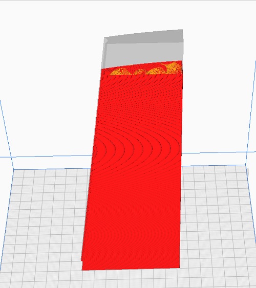
It works well enough. Being tapered is has strength and stiffness better in proportion to the loads that are applied and would save quite a bit of printing time and weight. It would be coupled to a similarly tapered aileron.
However a lofted surface only seems to print if it is vertical. The whole object of the Clark Y wing was to print it horizontally flat on the spar line but this is what you get.
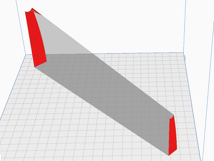
None of the lofted part of the wing is recognised by CURA!

I do recall I discovered the same thing when I tried to print a lofted duct horizontally on the bed.
It works well enough. Being tapered is has strength and stiffness better in proportion to the loads that are applied and would save quite a bit of printing time and weight. It would be coupled to a similarly tapered aileron.
However a lofted surface only seems to print if it is vertical. The whole object of the Clark Y wing was to print it horizontally flat on the spar line but this is what you get.
None of the lofted part of the wing is recognised by CURA!
I do recall I discovered the same thing when I tried to print a lofted duct horizontally on the bed.
Last edit: 01 Mar 2023 14:53 by Quorneng.
Thanks: Klipkopwildlife, jon.in.swansea
Please Log in or Create an account to join the conversation.
- Quorneng
-
Topic Author
- Offline
- Forum Master
-
Less
More
- Posts: 9436
- Thank you received: 19043
01 Mar 2023 22:55 #41
by Quorneng
Replied by Quorneng on topic Printing with Light Weight PLA
Not very significant but I have replaced the acetate aileron hinge with a printed version.

Being CAD based it means the pin hole can be positioned so it exactly matches the centre of the radii allowing the aileron 'fit' to be a bit closer.
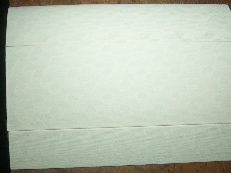
The gap is the same top and bottom yet it still retains free movement to over 45 degrees each way
The complete 240 mm long section with the aileron weighs 33.3g.
Being CAD based it means the pin hole can be positioned so it exactly matches the centre of the radii allowing the aileron 'fit' to be a bit closer.
The gap is the same top and bottom yet it still retains free movement to over 45 degrees each way
The complete 240 mm long section with the aileron weighs 33.3g.
Thanks: Klipkopwildlife
Please Log in or Create an account to join the conversation.
- Quorneng
-
Topic Author
- Offline
- Forum Master
-
Less
More
- Posts: 9436
- Thank you received: 19043
02 Mar 2023 21:27 - 02 Mar 2023 21:32 #42
by Quorneng
Replied by Quorneng on topic Printing with Light Weight PLA
Given that you can't, at least in CURA,, print lofted structures on their side and that LW-PLA has reaso able properties even when printed vertically I set about designing a tapered lofted LW=PLA wing that could be tested on the Blue Dragon.
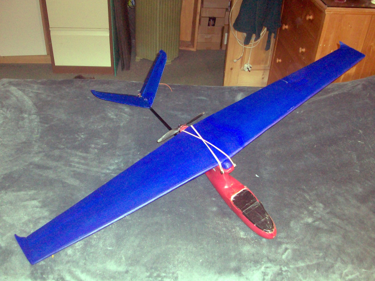
Its Depron wing, actually 5 mm underlay foam, is 1010 mm span and weighs 108g. The lofted wing will be slightly smaller at 960 mm (4x240mm).
It would take a total of about 20 hours to print all the bits and would weigh just over 100g, say 110 with aileron servos so pretty close..
The biggest problem will be printing each lofted aileron.
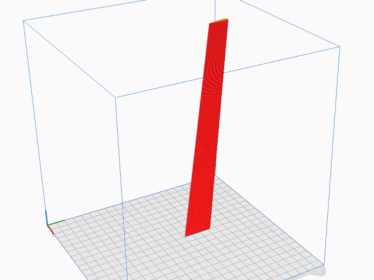
Now that is a tall print!
I might just print one aileron (1hr 12 min) just to see if it works.
Its Depron wing, actually 5 mm underlay foam, is 1010 mm span and weighs 108g. The lofted wing will be slightly smaller at 960 mm (4x240mm).
It would take a total of about 20 hours to print all the bits and would weigh just over 100g, say 110 with aileron servos so pretty close..
The biggest problem will be printing each lofted aileron.
Now that is a tall print!
I might just print one aileron (1hr 12 min) just to see if it works.
Last edit: 02 Mar 2023 21:32 by Quorneng.
Thanks: Klipkopwildlife
Please Log in or Create an account to join the conversation.
- Klipkopwildlife
-
- Away
- Administrator
-
- I'm supposed to be retired!
03 Mar 2023 07:20 - 03 Mar 2023 07:29 #43
by Klipkopwildlife
Do it now, you may never get another chance
Replied by Klipkopwildlife on topic Printing with Light Weight PLA
Simon, can I suggest you print the aileron at a diagonal, the base is very narrow for one axis. At 45o you will at least spread the load on the base.
Do it now, you may never get another chance
Last edit: 03 Mar 2023 07:29 by Klipkopwildlife.
Please Log in or Create an account to join the conversation.
- jon.in.swansea
-
- Offline
- Elite Member
-
Less
More
- Posts: 766
- Thank you received: 1192
03 Mar 2023 12:45 - 03 Mar 2023 12:47 #44
by jon.in.swansea
Replied by jon.in.swansea on topic Printing with Light Weight PLA
I have come to a cross-roads so looking for feedback. I printed on-the-diagonal the leading and trailing sections of wing (so I could get 220mm) and a very nicely tapered (in multiple directions) aileron as well as some experimental leading edge pieces - (more on that below). I strung these together with the lightweight ribs (average <1g each) and a CF tube. There are two normal PLA bits - a dihedral CF spar joiner and wing-end caps to protect the ailerons. The whole lot in the images below comes in at 120g for a 1m span and a root chord of 180mm (assuming a 3mm foam skin) and a tip chord of 140mm. The taper in thickness is 30mm at the CL and 11mm at the tip.

A close-up of the wing end....

Looking from below we see the end-cap as well as the aileron and a bit better view of a leading edge idea.
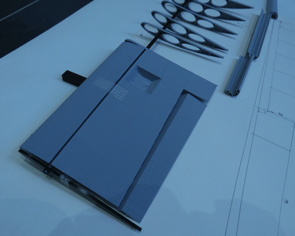
The leading edge idea is - I typically heat form the foam but the tight radius is quite a pain to get correct, especially if the wing cross-section is changing. So I took the Clarke-Y profile of the smaller and larger ribs and sketched something I could print in vase-mode. They have a tab so the 3mm foam can slip under. With there I will only need a limited forming of the foam although the weigh in at 12g.
So help me decide....
Do I take what I learned with the end-of-wing and loft and print the leading and trailing portions of the rest of the wing - a 220mm left and a 220mm right and a ~120mm centre-joining section? I need one void so I can run wiring but otherwise it would be 3% gyroid infil and I would rely on the CF spar for structure. Or continue with my hybrid of foam-over-ribs and printed wing-ends?
A close-up of the wing end....
Looking from below we see the end-cap as well as the aileron and a bit better view of a leading edge idea.
The leading edge idea is - I typically heat form the foam but the tight radius is quite a pain to get correct, especially if the wing cross-section is changing. So I took the Clarke-Y profile of the smaller and larger ribs and sketched something I could print in vase-mode. They have a tab so the 3mm foam can slip under. With there I will only need a limited forming of the foam although the weigh in at 12g.
So help me decide....
Do I take what I learned with the end-of-wing and loft and print the leading and trailing portions of the rest of the wing - a 220mm left and a 220mm right and a ~120mm centre-joining section? I need one void so I can run wiring but otherwise it would be 3% gyroid infil and I would rely on the CF spar for structure. Or continue with my hybrid of foam-over-ribs and printed wing-ends?
Last edit: 03 Mar 2023 12:47 by jon.in.swansea.
Thanks: Klipkopwildlife
Please Log in or Create an account to join the conversation.
- jon.in.swansea
-
- Offline
- Elite Member
-
Less
More
- Posts: 766
- Thank you received: 1192
03 Mar 2023 12:58 #45
by jon.in.swansea
Replied by jon.in.swansea on topic Printing with Light Weight PLA
CURA does not allow you to do the horizontal print. However the Prusa slicer takes what were originally vertical lofts and happily prints them horizontally. You don't have to use it with a Prusa printer so - its free, might be worth a short experiment to see if the g-code it spits out will work with your printer. There seem to be quite a few choices for adding other printer profiles although since I don't have another printer brand I have not tried that.
Thanks: Klipkopwildlife
Please Log in or Create an account to join the conversation.
Time to create page: 1.235 seconds