
- Posts: 757
- Thank you received: 1164
freeCAD and fuselage creation
- jon.in.swansea
-
 Topic Author
- Offline
- Elite Member
-

Less
More
10 May 2023 11:26 #166
by jon.in.swansea
Replied by jon.in.swansea on topic freeCAD and fuselage creation
I am currently out and about doing steam trains - (Severn Valley Railway and the Dean Forrest Railway thus far) and enjoying feeling 8 years old again instead of just shy of seven decades....
And I saw a video about a new curve tool in FreeCAD which looks like it would take a lot of the faffing around creating printable wings and perhaps fuselages. I previously had taken a sketch of a Clarke-Y and for a tapered wing I calculated the scaling for each rib. For my explorations of LW-PLA I took the Clarke-Y and used scaling manually to come up with sections to 'loft' the wing from. Lots of notes and faffing, especially if I wanted a wing that tapered in chord as well as thickness.
The link below is to a fellow building up a wing (he chose a rather silly wing shape but only to demonstrate the process). The curve tool allows you to take a sketch of a wing section as well as the plan layout and the thickness and it does the hard work. You tell it how many intermediate sections to create and it scales them and turns it into a solid. He also shows how to patch the fiddly bits if you don't like the wing tip. I learned a lot - haven't tried it yet. Once you get the hang of it it probably would take less time than the video to do.
And I saw a video about a new curve tool in FreeCAD which looks like it would take a lot of the faffing around creating printable wings and perhaps fuselages. I previously had taken a sketch of a Clarke-Y and for a tapered wing I calculated the scaling for each rib. For my explorations of LW-PLA I took the Clarke-Y and used scaling manually to come up with sections to 'loft' the wing from. Lots of notes and faffing, especially if I wanted a wing that tapered in chord as well as thickness.
The link below is to a fellow building up a wing (he chose a rather silly wing shape but only to demonstrate the process). The curve tool allows you to take a sketch of a wing section as well as the plan layout and the thickness and it does the hard work. You tell it how many intermediate sections to create and it scales them and turns it into a solid. He also shows how to patch the fiddly bits if you don't like the wing tip. I learned a lot - haven't tried it yet. Once you get the hang of it it probably would take less time than the video to do.
Thanks: Klipkopwildlife, Quorneng
Please Log in or Create an account to join the conversation.
- jon.in.swansea
-
Topic Author
- Offline
- Elite Member
-
Less
More
- Posts: 757
- Thank you received: 1164
26 Jun 2023 12:05 #167
by jon.in.swansea
Replied by jon.in.swansea on topic freeCAD and fuselage creation
Some time ago I made a post about a small printed part intended to prevent shorting of motor connectors. I am unable to locate the post which is a pity as it generated a bit of chatter.
It looked like below. The trouble is that it takes space, the 2g it weighs is less of an issue. It was meant to be Velcro-d to the side of the fuselage.

The LW-PLA fuselage in the Dragonfly2 is tight. I still worry about those exposed bits of brass in confined space. And then it came to me a much simpler device which is smaller and lighter. Takes less than 4 minutes to print, less than 1g. It is composed of three merged 5mm lengths of hollow tube (in the CAD tool) sized for the shrink-wrap on the bayonet coming from the ESC.
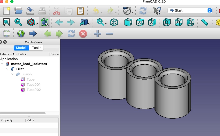

If the upload works I have zipped up both the freeCAD file (so you can resize as needed) plus the STL file.
-Jon
It looked like below. The trouble is that it takes space, the 2g it weighs is less of an issue. It was meant to be Velcro-d to the side of the fuselage.
The LW-PLA fuselage in the Dragonfly2 is tight. I still worry about those exposed bits of brass in confined space. And then it came to me a much simpler device which is smaller and lighter. Takes less than 4 minutes to print, less than 1g. It is composed of three merged 5mm lengths of hollow tube (in the CAD tool) sized for the shrink-wrap on the bayonet coming from the ESC.
If the upload works I have zipped up both the freeCAD file (so you can resize as needed) plus the STL file.
This attachment is hidden for guests.
Please log in or register to see it.
Please log in or register to see it.
-Jon
Attachments:
Thanks: Klipkopwildlife
Please Log in or Create an account to join the conversation.
- Quorneng
-

- Offline
- Forum Master
-

Less
More
- Posts: 10058
- Thank you received: 19043
26 Jun 2023 15:39 #168
by Quorneng
Replied by Quorneng on topic freeCAD and fuselage creation
jon
Neat but I am not sure you have the shrink wrap insulation correctly positioned.
The pin and socked shrink wrap insulation should look like this.

The socket which could be live is completely covered at all times.
The insulation on the pin, which is only live when connected, is arranged so there are no exposed areas when the pin and socket are fully connected.
Works for me on my motor wires..
Neat but I am not sure you have the shrink wrap insulation correctly positioned.
The pin and socked shrink wrap insulation should look like this.
The socket which could be live is completely covered at all times.
The insulation on the pin, which is only live when connected, is arranged so there are no exposed areas when the pin and socket are fully connected.
Works for me on my motor wires..
Attachments:
Thanks: Eric, Klipkopwildlife, jon.in.swansea
Please Log in or Create an account to join the conversation.
- Eric
-

- Offline
- Moderator
-

Less
More
- Posts: 15406
- Thank you received: 14306
26 Jun 2023 17:12 #169
by Eric
if you are calm and collected when all about you are going berserk - you've missed something important!
Replied by Eric on topic freeCAD and fuselage creation
I was going to say the same - - are your plugs fully inserted into the sockets, Jon?
if you are calm and collected when all about you are going berserk - you've missed something important!
Thanks: Klipkopwildlife
Please Log in or Create an account to join the conversation.
- Klipkopwildlife
-

- Offline
- Administrator
-

- I'm supposed to be retired!
26 Jun 2023 17:50 #170
by Klipkopwildlife
Do it now, you may never get another chance
Replied by Klipkopwildlife on topic freeCAD and fuselage creation
I think I know where Jons' problem is, the male is practically impossible to insert fully into the female (a problem I often had as a young man). That particular type of connector is extremely tight, I resorted to shrinking some tubing over each connector, well 2 of them.
Do it now, you may never get another chance
Thanks: Eric
Please Log in or Create an account to join the conversation.
- jon.in.swansea
-
Topic Author
- Offline
- Elite Member
-
Less
More
- Posts: 757
- Thank you received: 1164
26 Jun 2023 19:01 #171
by jon.in.swansea
Replied by jon.in.swansea on topic freeCAD and fuselage creation
I think the shrink-wrap creeps a bit with each re-connect. Yes, I should have thought to just put some new shrink on (rather obvious once said).
I do like having something to keep them tidy none-the-less.
I do like having something to keep them tidy none-the-less.
Thanks: Klipkopwildlife, Quorneng
Please Log in or Create an account to join the conversation.
- Eric
-
- Offline
- Moderator
-
Less
More
- Posts: 15406
- Thank you received: 14306
27 Jun 2023 07:33 #172
by Eric
if you are calm and collected when all about you are going berserk - you've missed something important!
Replied by Eric on topic freeCAD and fuselage creation
That brings us full-circle - back to where you are swapping components around between models.
It is much better to have one set in each model, then there is less mechanical stress on all the plugs and wires. The more you plug in and unplug, the slacker the connections get.
It is much better to have one set in each model, then there is less mechanical stress on all the plugs and wires. The more you plug in and unplug, the slacker the connections get.
if you are calm and collected when all about you are going berserk - you've missed something important!
Thanks: Klipkopwildlife, jon.in.swansea
Please Log in or Create an account to join the conversation.
- Klipkopwildlife
-
- Offline
- Administrator
-
- I'm supposed to be retired!
27 Jun 2023 08:40 #173
by Klipkopwildlife
Do it now, you may never get another chance
Replied by Klipkopwildlife on topic freeCAD and fuselage creation
I'm with you there Eric but it can get a bit daunting cost wise when you're starting out.
Do it now, you may never get another chance
Thanks: jon.in.swansea
Please Log in or Create an account to join the conversation.
- jon.in.swansea
-
Topic Author
- Offline
- Elite Member
-
Less
More
- Posts: 757
- Thank you received: 1164
27 Jun 2023 13:37 #174
by jon.in.swansea
Replied by jon.in.swansea on topic freeCAD and fuselage creation
Point taken on the components being swopped less frequently. I got a few receivers from Tony that I can devote to specific models now.
The connection that is increasingly frustrating for me is the battery connection to the ESC. Those T30s have a finite life and what with bending the battery or ESC wires each iteration I find myself replacing those connectors and having to re-solder.
The connection that is increasingly frustrating for me is the battery connection to the ESC. Those T30s have a finite life and what with bending the battery or ESC wires each iteration I find myself replacing those connectors and having to re-solder.
Thanks: Klipkopwildlife
Please Log in or Create an account to join the conversation.
- Klipkopwildlife
-
- Offline
- Administrator
-
- I'm supposed to be retired!
27 Jun 2023 17:12 #175
by Klipkopwildlife
Do it now, you may never get another chance
Replied by Klipkopwildlife on topic freeCAD and fuselage creation
We're all in the same boat there Jon, the best scenario is to buy a pair of small circlip pliers, drill a hole in each plug and socket and use the pliers to disconnect the plug and socket. Be very careful how far you drill in the plug and socket parts.
Do it now, you may never get another chance
Thanks: jon.in.swansea
Please Log in or Create an account to join the conversation.
- jon.in.swansea
-
Topic Author
- Offline
- Elite Member
-
Less
More
- Posts: 757
- Thank you received: 1164
07 Aug 2023 11:58 #176
by jon.in.swansea
Replied by jon.in.swansea on topic freeCAD and fuselage creation
I am thinking about my next wing. The foam and printed PLA rib Dragonfly original has a rectangular plan form but needs work as the servos for the ailerons have detached.
Given that I find heat-forming the leading edge of a Clarke-Y rather tedious in foam and the trailing edge difficult to make nice and shape I thought those might benefit from printing.
However, the tension cracks I find in LW-PLA wings is a bummer. So I am thinking about a different kind of hybrid - with printed leading and trailing edges and the balance made up of a foam skin (with tape covering for colour and tension) and with LW-PLA ribs and CF spars.
The prior wing had a constant chord of 5" and a 1m span so 190 sq inch area. I found the taper plan I used in the LW-PLA wing to be rather fun but there were comments that it might be better to shift the taper from mostly at the trailing edge. So I opened up the aero toolbox site and looked at what I might get with 190-200 sq inches and different sweep angles.
The first with a 3 degree sweep would introduce complexities at the leading and trailing edges and design of the ribs. An aspect ratio of 10 should limit drag.

I tried some variant sweeps to shift the taper to the leading edge which simplifies the aileron and trailing edge. I can have a perpendicular-to-the-fuse trailing spar.

Question - should the main spar be perpendicular to the fuse or follow along the sweep of the chord?
If I decrease the desired wing area I need a bit more sweep and end up with a bit more taper.

If I drop the span a bit I get a chunkier wing with less taper and a similar aspect ratio as my recent LW-PLA wing.

My thought is to design the printed leading edge to ~12.5 % of the chord (where most of the curve happens). And the ailerons along about 2/3 of the trailing edge and ~20% of the chord. I would 'print' the ailerons and the equivalent non-aileron bit of the trailing edge. Ribs would be LW-PLA at ~60mm intervals and tab into the leading and trailing edges.
Anone have pointers and preferences about these shapes?
Given that I find heat-forming the leading edge of a Clarke-Y rather tedious in foam and the trailing edge difficult to make nice and shape I thought those might benefit from printing.
However, the tension cracks I find in LW-PLA wings is a bummer. So I am thinking about a different kind of hybrid - with printed leading and trailing edges and the balance made up of a foam skin (with tape covering for colour and tension) and with LW-PLA ribs and CF spars.
The prior wing had a constant chord of 5" and a 1m span so 190 sq inch area. I found the taper plan I used in the LW-PLA wing to be rather fun but there were comments that it might be better to shift the taper from mostly at the trailing edge. So I opened up the aero toolbox site and looked at what I might get with 190-200 sq inches and different sweep angles.
The first with a 3 degree sweep would introduce complexities at the leading and trailing edges and design of the ribs. An aspect ratio of 10 should limit drag.
I tried some variant sweeps to shift the taper to the leading edge which simplifies the aileron and trailing edge. I can have a perpendicular-to-the-fuse trailing spar.
Question - should the main spar be perpendicular to the fuse or follow along the sweep of the chord?
If I decrease the desired wing area I need a bit more sweep and end up with a bit more taper.
If I drop the span a bit I get a chunkier wing with less taper and a similar aspect ratio as my recent LW-PLA wing.
My thought is to design the printed leading edge to ~12.5 % of the chord (where most of the curve happens). And the ailerons along about 2/3 of the trailing edge and ~20% of the chord. I would 'print' the ailerons and the equivalent non-aileron bit of the trailing edge. Ribs would be LW-PLA at ~60mm intervals and tab into the leading and trailing edges.
Anone have pointers and preferences about these shapes?


Thanks: Klipkopwildlife
Please Log in or Create an account to join the conversation.
- Klipkopwildlife
-
- Offline
- Administrator
-
- I'm supposed to be retired!
07 Aug 2023 12:39 #177
by Klipkopwildlife
Do it now, you may never get another chance
Replied by Klipkopwildlife on topic freeCAD and fuselage creation
Jon, given that most model aircraft wings have been constant chord for years, why bother with a taper wing unless it's looking towards the future? A scale model possibly?
I see where you're going with the composite wing though, however there will come a time when you won't need it, you just need a bit more practice.

I see where you're going with the composite wing though, however there will come a time when you won't need it, you just need a bit more practice.
Do it now, you may never get another chance
Thanks: jon.in.swansea
Please Log in or Create an account to join the conversation.
- Eric
-
- Offline
- Moderator
-
Less
More
- Posts: 15406
- Thank you received: 14306
07 Aug 2023 15:16 #178
by Eric
if you are calm and collected when all about you are going berserk - you've missed something important!
Replied by Eric on topic freeCAD and fuselage creation
Klippy put - most model aircraft wings have been constant chord for years
I would agree with that for the typical club trainer model, mainly because the (then) kit-built parallel chord was easier to build straight!
But lots of models have swept wings of various degrees, go as far back as the 1960's MFA Chevron, for example. Try to find a large-span plank-wing glider - you can't, they are all tapered.
The same applies to full-size, there are a few plank-wings, the Tipsy Nipper, etc (mostly homebuilds or PFA) but even the humble Jodel has a tapered outer on the inner plank section. I think the popular Piper Cherokee has a plank-wing, but the equally popular Cessna doesn't.
I would agree with that for the typical club trainer model, mainly because the (then) kit-built parallel chord was easier to build straight!
But lots of models have swept wings of various degrees, go as far back as the 1960's MFA Chevron, for example. Try to find a large-span plank-wing glider - you can't, they are all tapered.
The same applies to full-size, there are a few plank-wings, the Tipsy Nipper, etc (mostly homebuilds or PFA) but even the humble Jodel has a tapered outer on the inner plank section. I think the popular Piper Cherokee has a plank-wing, but the equally popular Cessna doesn't.
if you are calm and collected when all about you are going berserk - you've missed something important!
Thanks: Klipkopwildlife, jon.in.swansea
Please Log in or Create an account to join the conversation.
- jon.in.swansea
-
Topic Author
- Offline
- Elite Member
-
Less
More
- Posts: 757
- Thank you received: 1164
07 Aug 2023 16:50 #179
by jon.in.swansea
Replied by jon.in.swansea on topic freeCAD and fuselage creation
Thanks for mentioning swept and tapered wings.
AND there were a couple of questions in the post - if the leading edge is swept should the main CF spar also be swept?
AND there were a couple of questions in the post - if the leading edge is swept should the main CF spar also be swept?
Please Log in or Create an account to join the conversation.
- jon.in.swansea
-
Topic Author
- Offline
- Elite Member
-
Less
More
- Posts: 757
- Thank you received: 1164
07 Aug 2023 16:57 #180
by jon.in.swansea
Replied by jon.in.swansea on topic freeCAD and fuselage creation
And why try a hybrid printed and foam wing? - Well it is a combination I have not tried. It might be an interesting mix using the better bits of prior designs.
I have been sketching possible cross sections. Certainly a head scratcher in places. It would force me to learn some new CAD tricks.
I have been sketching possible cross sections. Certainly a head scratcher in places. It would force me to learn some new CAD tricks.
Please Log in or Create an account to join the conversation.
Time to create page: 0.899 seconds