
- Posts: 587
- Thank you received: 1047
A go at a Foamie
- Magpie
-
 Topic Author
- Offline
- Elite Member
-

Less
More
16 Jul 2025 07:39 - 16 Jul 2025 07:50 #61
by Magpie
Replied by Magpie on topic A go at a Foamie
Q's doppelganger and others have used the LE2204 on their FX707's.
forums.modelflying.co.uk/index.php?/topi...ons/page/2/#comments
The internal motor winding has been pulled out & twisted beyond use.
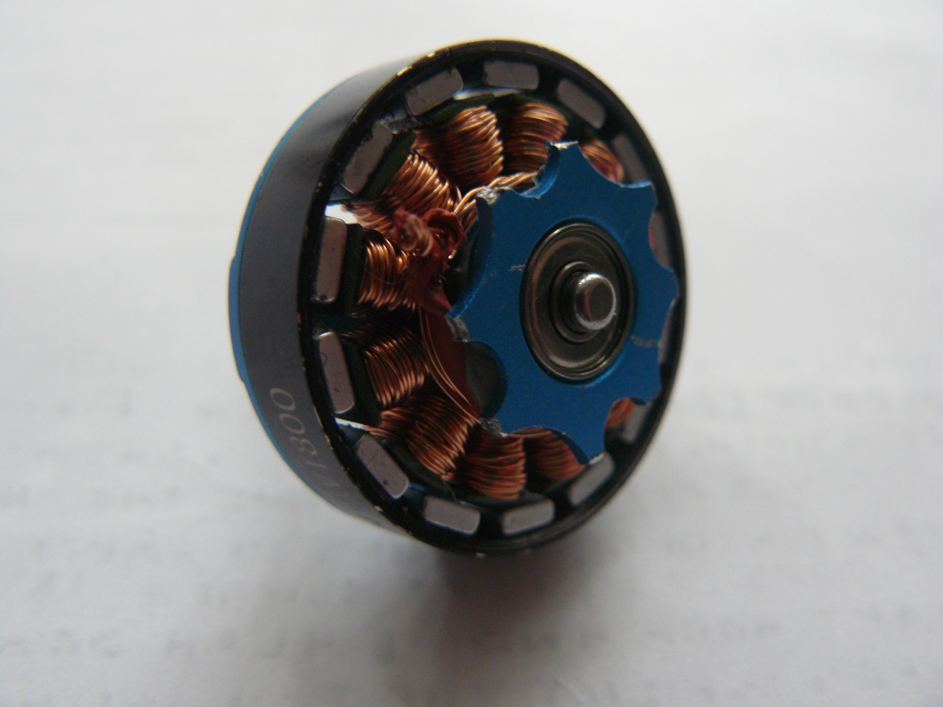
Note I have removed the circlip on the end of the shaft to see If I could dismantle the motor but the bearing must be pressed in.
forums.modelflying.co.uk/index.php?/topi...ons/page/2/#comments
The internal motor winding has been pulled out & twisted beyond use.
Note I have removed the circlip on the end of the shaft to see If I could dismantle the motor but the bearing must be pressed in.
Attachments:
Last edit: 16 Jul 2025 07:50 by Magpie.
Thanks: Klipkopwildlife
Please Log in or Create an account to join the conversation.
- Magpie
-
Topic Author
- Offline
- Elite Member
-
Less
More
- Posts: 587
- Thank you received: 1047
16 Jul 2025 08:26 - 16 Jul 2025 08:51 #62
by Magpie
Replied by Magpie on topic A go at a Foamie
I've taken some photos of the folding prop.
This is the back view of one of the 7.5 x 4 props straight out of the packet. The blade pivots are a reasonably close fit in the plastic housing.

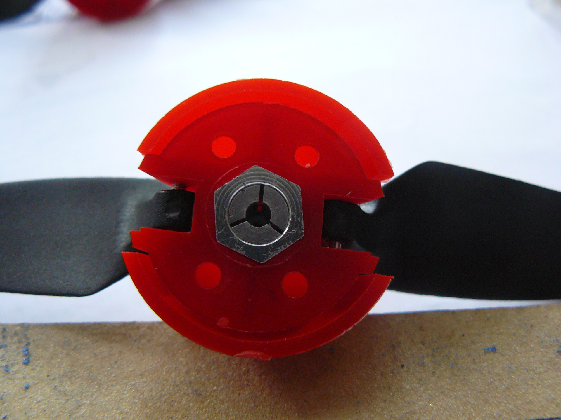
This is a back view of the 6 x 4 prop in use when the motor failed, there is a gap at the side of the blade pivot
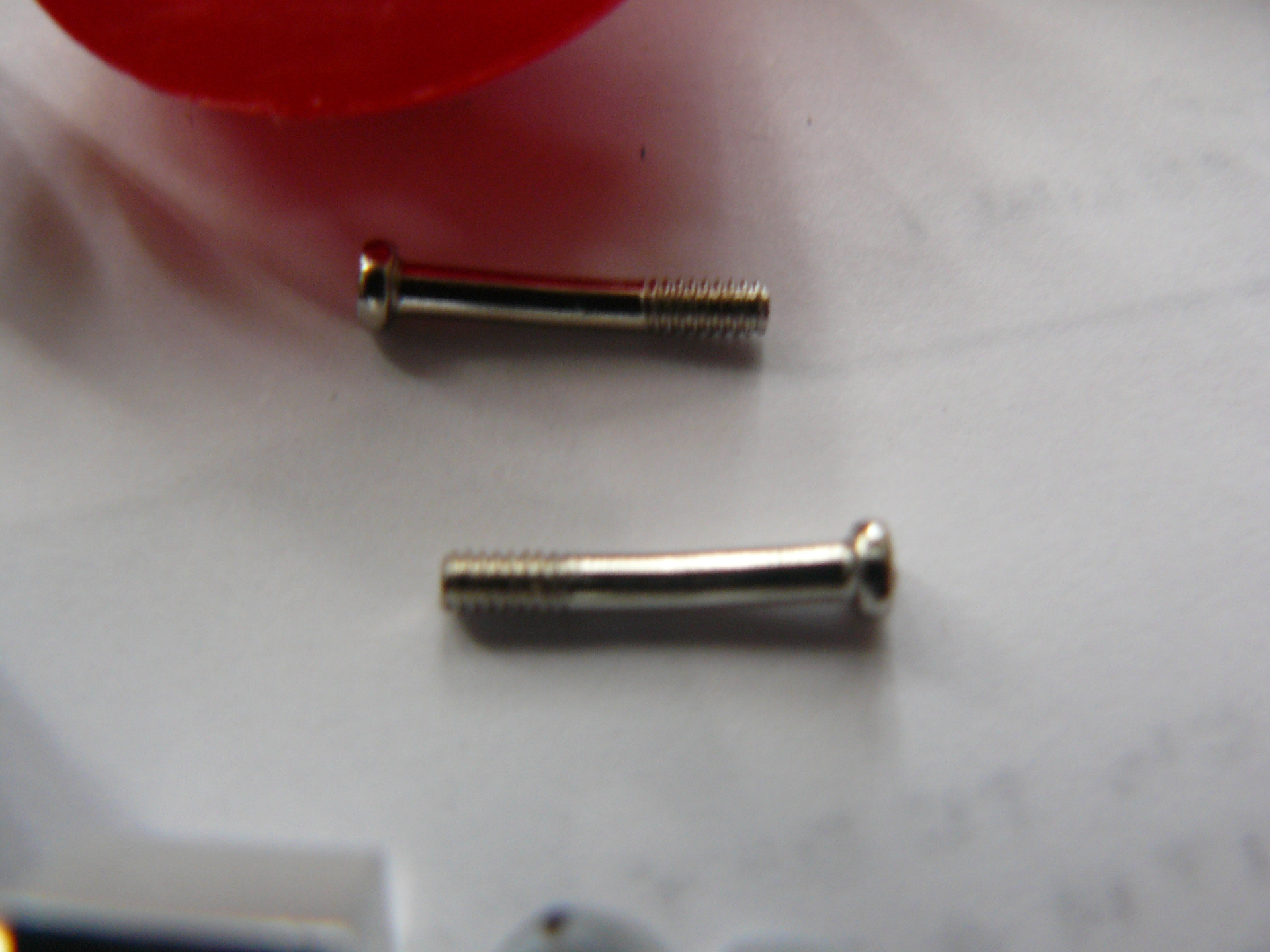
This is the prop dismantled. Note that the pivot screws are bent.
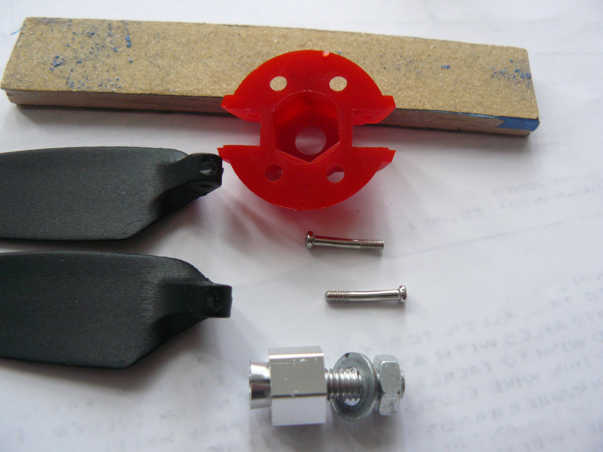
It looks to me that the cause of the vibration was too much side play on the blades.
I assume the bent pivot screw was the result of the vibration.
I had bought two 6 x 4 and two 7.5 x 4, that being what was available.
Both the 7.5's are a reasonable fit, the other 6 x 4 also has alot of side play. It suggests that the 6 x 4's were from the same batch, possibly assembled by the same person,
The pivots on the 6" blades are 4.9mm thick, those on the 7.5" blades are 5.9mm.
Should different plastic housings have been used on the different sized blades?
They were all got from Aliexpress. I'll try complaining but I'm not optimistic.
This is the back view of one of the 7.5 x 4 props straight out of the packet. The blade pivots are a reasonably close fit in the plastic housing.
This is a back view of the 6 x 4 prop in use when the motor failed, there is a gap at the side of the blade pivot
This is the prop dismantled. Note that the pivot screws are bent.
It looks to me that the cause of the vibration was too much side play on the blades.
I assume the bent pivot screw was the result of the vibration.
I had bought two 6 x 4 and two 7.5 x 4, that being what was available.
Both the 7.5's are a reasonable fit, the other 6 x 4 also has alot of side play. It suggests that the 6 x 4's were from the same batch, possibly assembled by the same person,
The pivots on the 6" blades are 4.9mm thick, those on the 7.5" blades are 5.9mm.
Should different plastic housings have been used on the different sized blades?
They were all got from Aliexpress. I'll try complaining but I'm not optimistic.
Attachments:
Last edit: 16 Jul 2025 08:51 by Magpie.
Thanks: Klipkopwildlife, THE BLACKBIRD
Please Log in or Create an account to join the conversation.
- Eric
-

- Offline
- Moderator
-

Less
More
- Posts: 15406
- Thank you received: 14306
16 Jul 2025 10:42 #63
by Eric
if you are calm and collected when all about you are going berserk - you've missed something important!
Replied by Eric on topic A go at a Foamie
It looks like the spinner back-plate has failed, as well. There's a chunk missing from both sides, and there's a crack on the lower right side.
It also looks - to me - that the blades are the wrong ones for that unit, as the blades appear to be too fat to fold flat without catching the back-plate. The blade hubs are too short!
It also looks - to me - that the blades are the wrong ones for that unit, as the blades appear to be too fat to fold flat without catching the back-plate. The blade hubs are too short!
if you are calm and collected when all about you are going berserk - you've missed something important!
Thanks: Klipkopwildlife, THE BLACKBIRD
Please Log in or Create an account to join the conversation.
- THE BLACKBIRD
-

- Offline
- Forum Master
-

Less
More
- Posts: 6781
- Thank you received: 10722
16 Jul 2025 11:50 #64
by THE BLACKBIRD
Replied by THE BLACKBIRD on topic A go at a Foamie
I would have thought the last thing you need for the hub of a folding prop assembly is plastic, should it not be ally
Thanks: Klipkopwildlife
Please Log in or Create an account to join the conversation.
- Magpie
-
Topic Author
- Offline
- Elite Member
-
Less
More
- Posts: 587
- Thank you received: 1047
16 Jul 2025 11:51 #65
by Magpie
Replied by Magpie on topic A go at a Foamie
I cannot see a missing chunk or a crack. I think maybe the camera angle & lighting is creating some illusion so I have scanned all four of the props.
The top one is the one that had been on the motor when it failed, I have put some washers in as spacers (more on that later). The next one is the other 6" prop & the other two are the 7.5".

The top one is the one that had been on the motor when it failed, I have put some washers in as spacers (more on that later). The next one is the other 6" prop & the other two are the 7.5".
Attachments:
Please Log in or Create an account to join the conversation.
- Magpie
-
Topic Author
- Offline
- Elite Member
-
Less
More
- Posts: 587
- Thank you received: 1047
16 Jul 2025 12:06 - 16 Jul 2025 12:07 #66
by Magpie
Replied by Magpie on topic A go at a Foamie
I added some washers to the 6" prop that had been on when the motor failed & mounted it on an A2212 motor on my test rig using a 3.17mm collet to match the motor shaft.
I didn't get the roaring vibration but I did not push it too far.
I then tried the other 6" prop without any washers.
I couldn't hear any difference between the two but my hearing is not of the best.
I have ordered a sound level meter. I will have to drive the ESC from my Raspberry Pi so I know I'm running the two props at the same speed.
I am now wondering whether the LE2204 motor is acting like a tuning fork (or the Tay Bridge).
I didn't get the roaring vibration but I did not push it too far.
I then tried the other 6" prop without any washers.
I couldn't hear any difference between the two but my hearing is not of the best.
I have ordered a sound level meter. I will have to drive the ESC from my Raspberry Pi so I know I'm running the two props at the same speed.
I am now wondering whether the LE2204 motor is acting like a tuning fork (or the Tay Bridge).
Last edit: 16 Jul 2025 12:07 by Magpie.
Thanks: Klipkopwildlife
Please Log in or Create an account to join the conversation.
- Quorneng
-

- Offline
- Forum Master
-
Less
More
- Posts: 10058
- Thank you received: 19043
16 Jul 2025 12:08 - 16 Jul 2025 12:08 #67
by Quorneng
Replied by Quorneng on topic A go at a Foamie
If you really bent those blade retaining screws simply from just the vibration then I am not surprised the motor back plate failed!
I would suggest that any noticeable vibration at 1/4 throttle means stop and cure the balance.
Out of balance forces increase by the square of the RPM. 1/4 to full throttle means at least 16 times the forces.
A really rigid test mount doesn't help.
Note on the full power run of the rotary although the test stand was loaded down with a big lead weight it was also sitting on a 5mm thick foam pad to allow it to move about a bit to absorb any vibration.
www.youtube.com/shorts/kOjTkcVH5x8
I would suggest that any noticeable vibration at 1/4 throttle means stop and cure the balance.
Out of balance forces increase by the square of the RPM. 1/4 to full throttle means at least 16 times the forces.
A really rigid test mount doesn't help.
Note on the full power run of the rotary although the test stand was loaded down with a big lead weight it was also sitting on a 5mm thick foam pad to allow it to move about a bit to absorb any vibration.
www.youtube.com/shorts/kOjTkcVH5x8
Last edit: 16 Jul 2025 12:08 by Quorneng.
Thanks: Klipkopwildlife
Please Log in or Create an account to join the conversation.
- Magpie
-
Topic Author
- Offline
- Elite Member
-
Less
More
- Posts: 587
- Thank you received: 1047
16 Jul 2025 12:35 #68
by Magpie
Replied by Magpie on topic A go at a Foamie
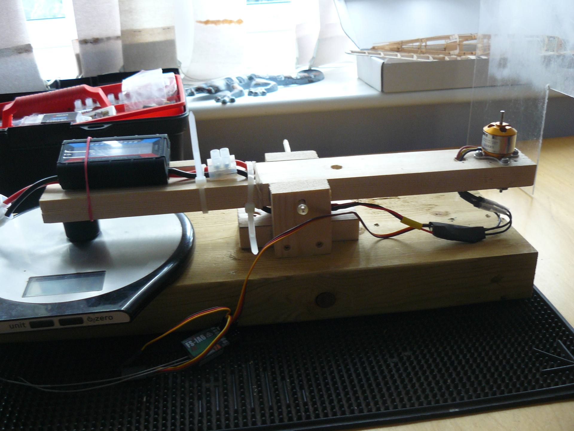
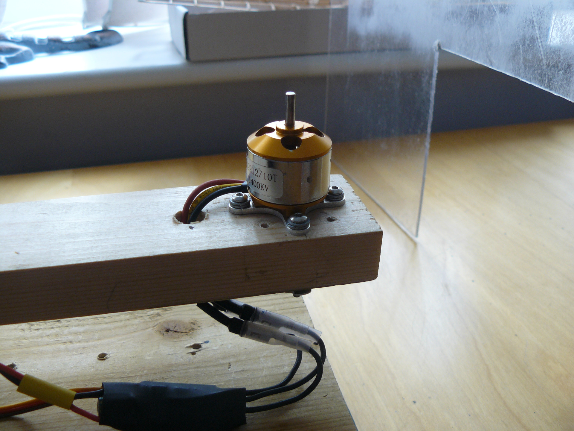
I don't know what the pivot screws are made of but they are magnetic.
They could only bend if there was a gap (which there is) between the blade & the side walls.
The vibration started at just over 50% ish.
The motors are mounted on the 2x1 arm using screws through it into T-nuts.
Maybe if I mounted a piece of ply on short stand-offs on top of the arm & fastened the motor to that it would reduce the resonance.
The whole thing stands on a car floor mat to help quieten it.
They could only bend if there was a gap (which there is) between the blade & the side walls.
The vibration started at just over 50% ish.
The motors are mounted on the 2x1 arm using screws through it into T-nuts.
Maybe if I mounted a piece of ply on short stand-offs on top of the arm & fastened the motor to that it would reduce the resonance.
The whole thing stands on a car floor mat to help quieten it.
Attachments:
Thanks: Klipkopwildlife
Please Log in or Create an account to join the conversation.
- Klipkopwildlife
-

- Offline
- Administrator
-

- I'm supposed to be retired!
16 Jul 2025 14:12 - 16 Jul 2025 14:14 #69
by Klipkopwildlife
Do it now, you may never get another chance
Replied by Klipkopwildlife on topic A go at a Foamie
I feel the gap is the root cause of the unbalance, I'm not surprised the screws bent, the G forces are enormous at close to WOT.
75% would be about 13k rpm
75% would be about 13k rpm
Do it now, you may never get another chance
Last edit: 16 Jul 2025 14:14 by Klipkopwildlife.
Please Log in or Create an account to join the conversation.
- Eric
-
- Offline
- Moderator
-
Less
More
- Posts: 15406
- Thank you received: 14306
16 Jul 2025 18:07 #70
by Eric
if you are calm and collected when all about you are going berserk - you've missed something important!
Replied by Eric on topic A go at a Foamie
Looking at the photo of the backplate leaning on the sanding block. Look at the slots for the prop blades. Both slots APPEAR to have a triangular piece missing from their upper edges.
Just out of curiosity, put the clamping bolt back in, and fit the backplate to the motor, without blades, bolts, or spinner, and give that a run, to see if that gives the motor the 'shakes'
Just out of curiosity, put the clamping bolt back in, and fit the backplate to the motor, without blades, bolts, or spinner, and give that a run, to see if that gives the motor the 'shakes'
if you are calm and collected when all about you are going berserk - you've missed something important!
Thanks: Klipkopwildlife
Please Log in or Create an account to join the conversation.
- Magpie
-
Topic Author
- Offline
- Elite Member
-
Less
More
- Posts: 587
- Thank you received: 1047
16 Jul 2025 20:47 #71
by Magpie
Replied by Magpie on topic A go at a Foamie
I cannot see what you mean.
Can you see the missing piece on the slots on the scanned image?
Remember the motor is a write-off. I've got to wait for a replacement before I can do much more.
Can you see the missing piece on the slots on the scanned image?
Remember the motor is a write-off. I've got to wait for a replacement before I can do much more.
Thanks: Klipkopwildlife
Please Log in or Create an account to join the conversation.
- Magpie
-
Topic Author
- Offline
- Elite Member
-
Less
More
- Posts: 587
- Thank you received: 1047
19 Jul 2025 15:53 #72
by Magpie
Replied by Magpie on topic A go at a Foamie
Apart from being short of clevices I've got the wings assembled. I've got a problem though managing all the servo cables. I've got ready-made extensions & a Y-lead but its going to be a struggle getting them all into the space under the wings in the fuselage. Jamming them in will run the risk of them getting entangled with the tail & fin servos so I'm thinking of cutting & soldering them. I've done alot of soldering in my time but these wires are very thin for my eyesight & dexterity.
The replacement motors should arrive this week so that means some very carefull testing on my rig. I've bought a cheap sound level meter, I can't think of any other way to monitor the vibration.
The replacement motors should arrive this week so that means some very carefull testing on my rig. I've bought a cheap sound level meter, I can't think of any other way to monitor the vibration.
Thanks: Klipkopwildlife, THE BLACKBIRD
Please Log in or Create an account to join the conversation.
- Eric
-
- Offline
- Moderator
-
Less
More
- Posts: 15406
- Thank you received: 14306
19 Jul 2025 17:42 #73
by Eric
if you are calm and collected when all about you are going berserk - you've missed something important!
Replied by Eric on topic A go at a Foamie
To stop your wires tangling in the servos, cut a piece of stiffish clear acrylic or acetate sheet to fit the fuselage length and width over the servos, mount it on a pair of rails, then you can see that everything is ok, and the wires are held away.
Or use shorter pre-made wires!
Or use shorter pre-made wires!
if you are calm and collected when all about you are going berserk - you've missed something important!
Thanks: Klipkopwildlife, THE BLACKBIRD
Please Log in or Create an account to join the conversation.
- Magpie
-
Topic Author
- Offline
- Elite Member
-
Less
More
- Posts: 587
- Thank you received: 1047
20 Jul 2025 09:17 - 20 Jul 2025 09:21 #74
by Magpie
Replied by Magpie on topic A go at a Foamie
There isn't enough headroom over the servo arms, I'd had to lower the servos so as they didn't foul the wings. I've used the shortest leads I could get, the connectors are quite large, about 35mm joined up & rigid.
I'll do as you suggest but put in a thin vertical barrier which will reach right up to the wing lower surface.
My replacement motors should come in the next day or two then I can see whereabouts under the canopy the battery has to go to get the CG in the right place. That will determine where the receiver can go (under the wing or under the canopy) & hence what space there is for the wiring.
I'll do as you suggest but put in a thin vertical barrier which will reach right up to the wing lower surface.
My replacement motors should come in the next day or two then I can see whereabouts under the canopy the battery has to go to get the CG in the right place. That will determine where the receiver can go (under the wing or under the canopy) & hence what space there is for the wiring.
Last edit: 20 Jul 2025 09:21 by Magpie.
Thanks: Klipkopwildlife, THE BLACKBIRD
Please Log in or Create an account to join the conversation.
- Quorneng
-
- Offline
- Forum Master
-
Less
More
- Posts: 10058
- Thank you received: 19043
20 Jul 2025 12:55 - 20 Jul 2025 12:56 #75
by Quorneng
Replied by Quorneng on topic A go at a Foamie
On small light planes I hate using servo extensions both for the space the connectors require and their weight.
Soldering 32 AWG servo wire is also a bit of a fiddly chore but it is worth the effort so every lead including the motor and ESC has just a single plug on it and is exactly the right length.
Even better if you can get the servos out the way as well
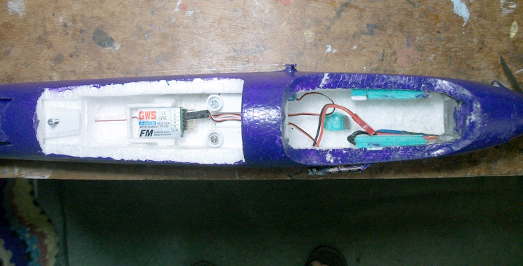
Loads of room!

Soldering 32 AWG servo wire is also a bit of a fiddly chore but it is worth the effort so every lead including the motor and ESC has just a single plug on it and is exactly the right length.
Even better if you can get the servos out the way as well
Loads of room!
Attachments:
Last edit: 20 Jul 2025 12:56 by Quorneng.
Thanks: Eric, Klipkopwildlife, Flytilbroke, THE BLACKBIRD, jon.in.swansea
Please Log in or Create an account to join the conversation.
Time to create page: 0.261 seconds