
Tiger Moth
- Klipkopwildlife
-
 Topic Author
- Offline
- Administrator
-

- I'm supposed to be retired!
Still a lot of intuition required though.
Only the first 3 formers can be glued vertical, as you can see from the above none of the other formers are vertical. I took the angle from the side panel then glued the former at the correct position.
Do it now, you may never get another chance
Please Log in or Create an account to join the conversation.
- Klipkopwildlife
-
Topic Author
- Offline
- Administrator
-
- I'm supposed to be retired!
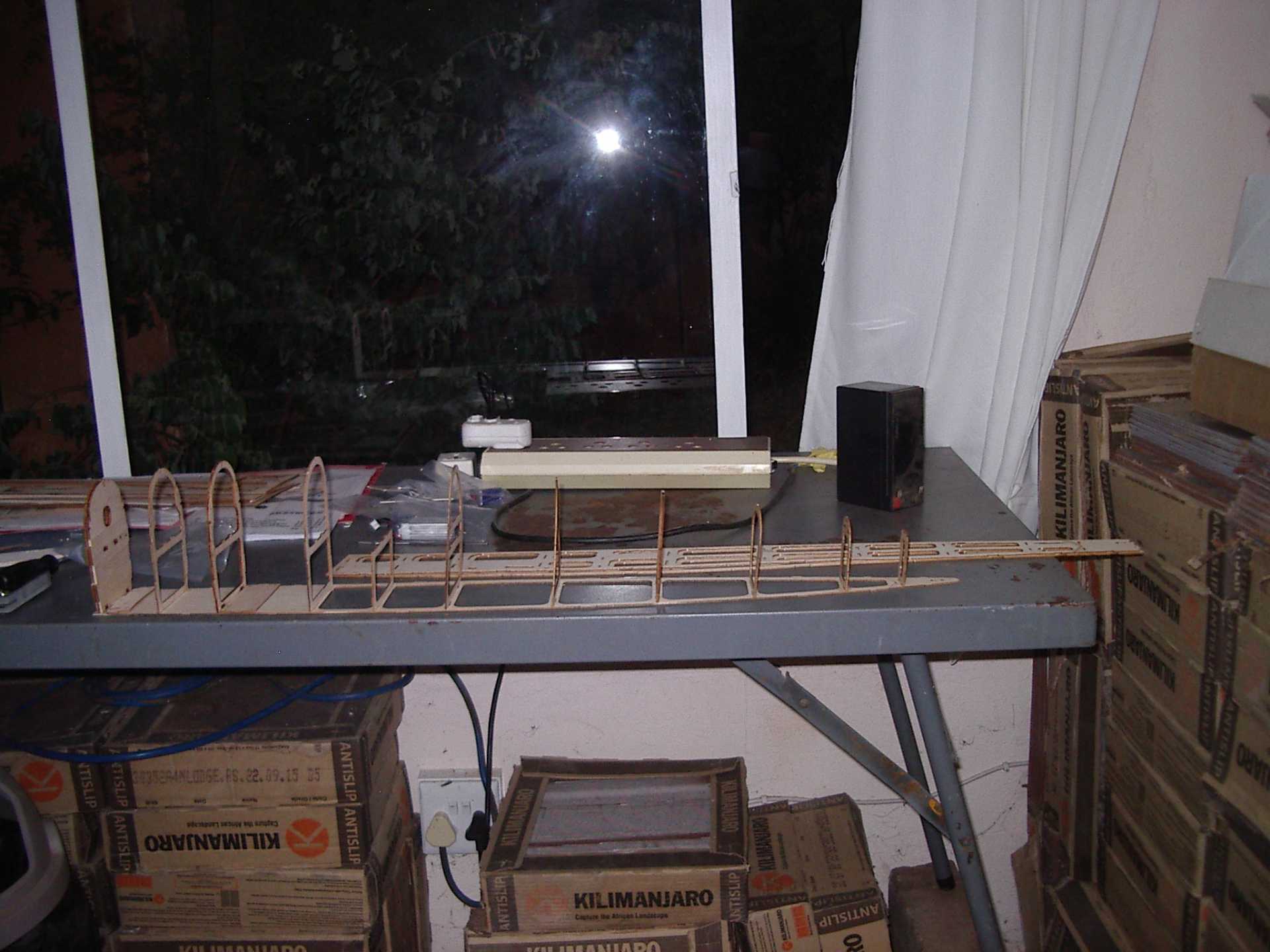
All of the formers now glued in position.
You can now also glue in A19 and A35 braces, with the additional P4 and P3 on top of them if you are going glow.
When dry we are going to trial fit the fuselage sides.
Do it now, you may never get another chance
Please Log in or Create an account to join the conversation.
- Klipkopwildlife
-
Topic Author
- Offline
- Administrator
-
- I'm supposed to be retired!

I'm a bit concerned about the position of A14, it would appear to be right where I want to put the fuel tank!
Do it now, you may never get another chance
Please Log in or Create an account to join the conversation.
- Quorneng
-

- Offline
- Forum Master
-

- Posts: 9436
- Thank you received: 19043

Please Log in or Create an account to join the conversation.
- Eric
-

- Offline
- Moderator
-

- Posts: 13726
- Thank you received: 14467
if you are calm and collected when all about you are going berserk - you've missed something important!
Please Log in or Create an account to join the conversation.
- Klipkopwildlife
-
Topic Author
- Offline
- Administrator
-
- I'm supposed to be retired!
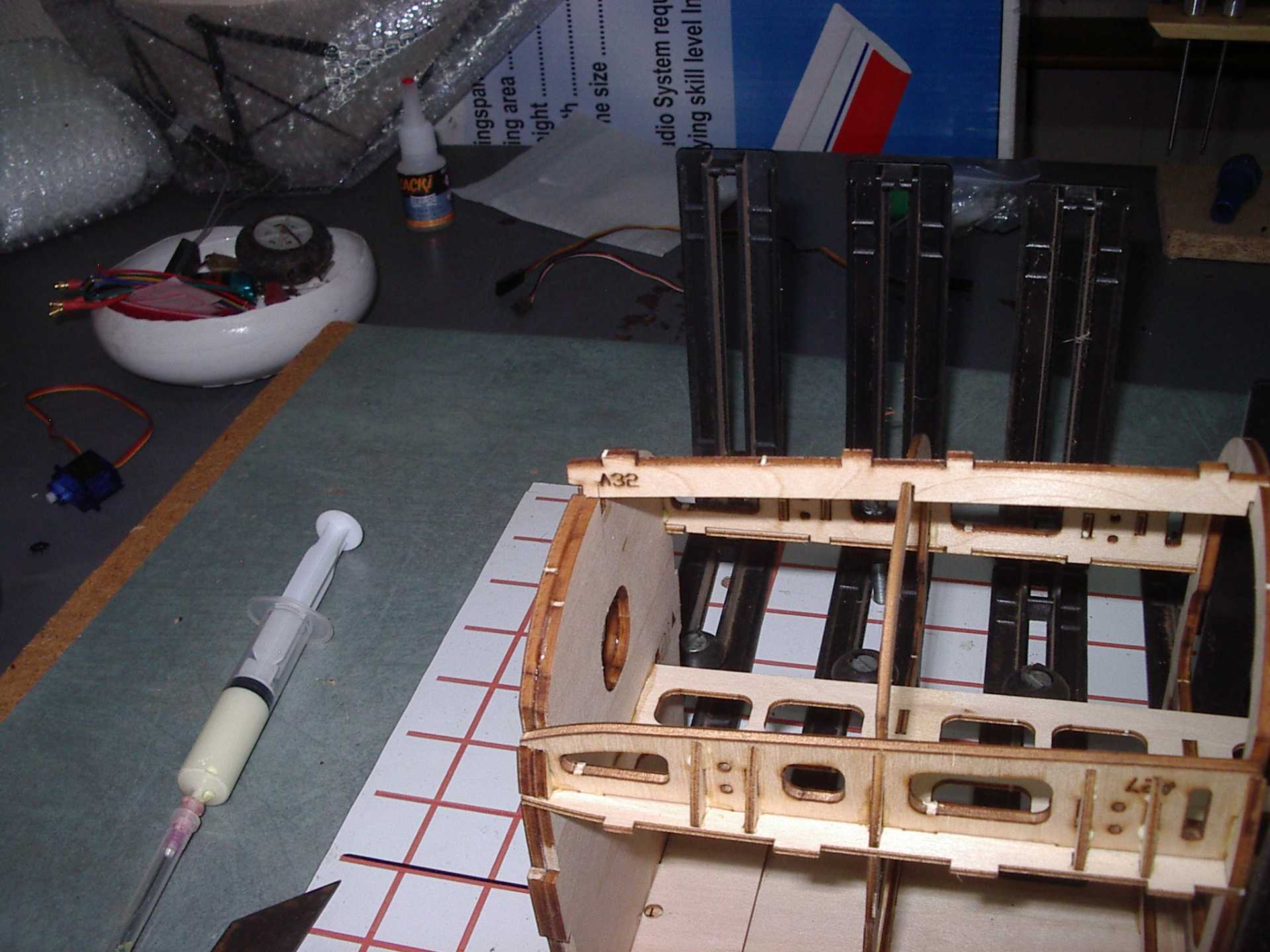
Well even after installing A14 I still wasn't happy with the rigidity so I decided to put in the rest of the nose pieces.

Which threw up a problem, the cut out for A22 where it goes into A1 is too short! I've had to cut back A22 to make it fit, the right way to do it would be to cut the slot in the second A1 a bit deeper, too late now. Watch out for A26, there are 8 of them (4 each side) they are different lengths, the shortest at the front. Glue them into A27, then glue in A27 which also has the same problem as A22

Do it now, you may never get another chance
Please Log in or Create an account to join the conversation.
- Klipkopwildlife
-
Topic Author
- Offline
- Administrator
-
- I'm supposed to be retired!

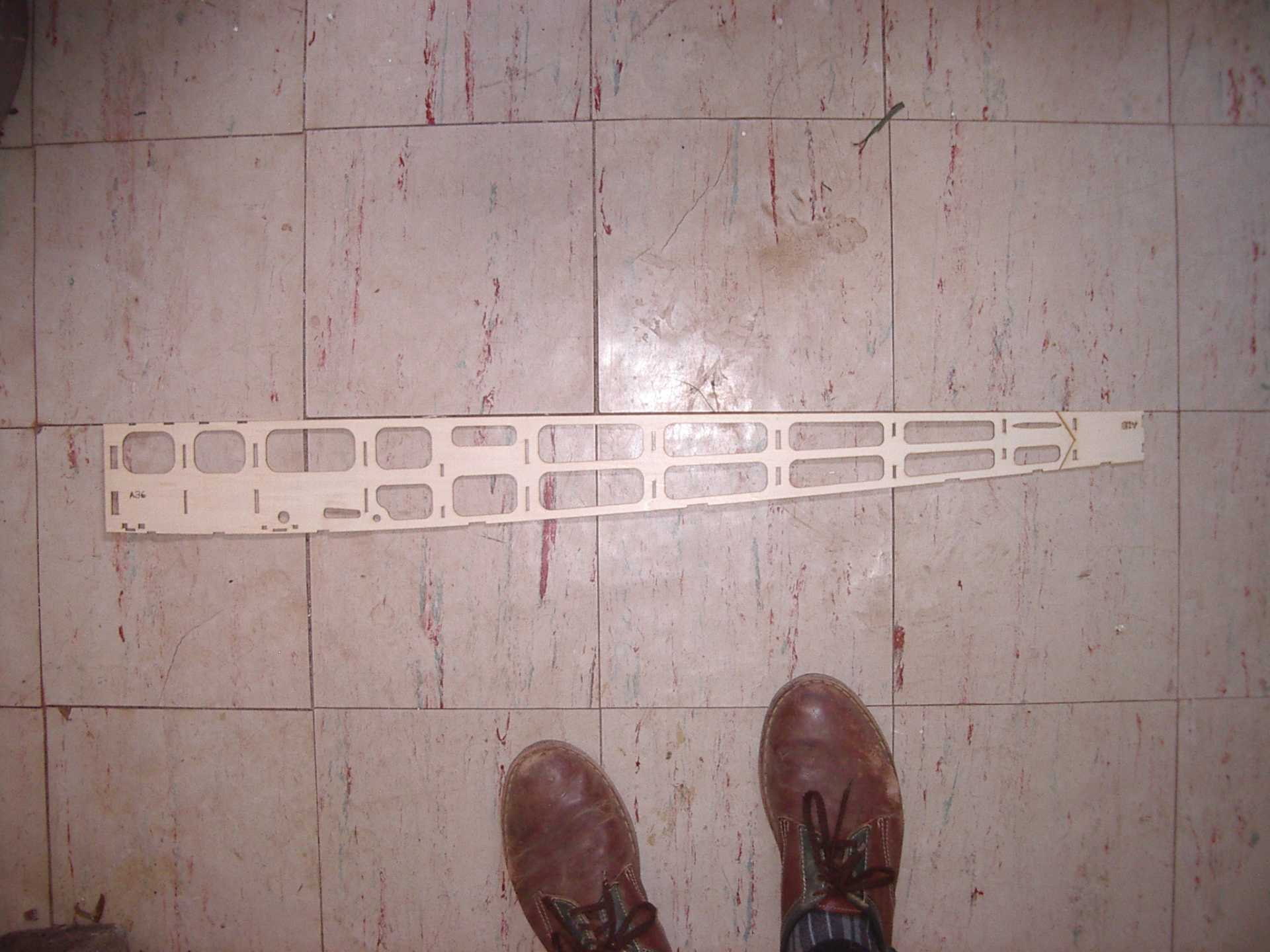
Now dry I feel the nose section is rigid enough to support the fuselage sides, but first butt glue the side extension pieces A18 to the sides A36.

The sides are cut out of 2 different sheets of crumble wood, I also found the thicknesses differed, 1.9mm and 2.04mm. I started to glue the thick A18 to the thin A36 which gave a noticeable step, luckily the glue hadn't set.
The fits are so tight that I wouldn't recommend dry fitting more than twice!
Once fitted you can final fit the sides and glue back to former A7. While still wet check that the tail ends of the sides meet without any vertical disparity.
Do it now, you may never get another chance
Please Log in or Create an account to join the conversation.
- Klipkopwildlife
-
Topic Author
- Offline
- Administrator
-
- I'm supposed to be retired!

Once dry you can apply glue and pull in the tail section.

Do it now, you may never get another chance
Please Log in or Create an account to join the conversation.
- one tenor
-

- Offline
- Forum Veteran
-

- johnpcalex@gmail.com
Anything will fly given enough power
Please Log in or Create an account to join the conversation.
- Klipkopwildlife
-
Topic Author
- Offline
- Administrator
-
- I'm supposed to be retired!

Are 9 gram servos going to cut the mustard? And secondly the pics show the output arm very close to the former, which I think might limit the rotation. Comments please.
Do it now, you may never get another chance
Please Log in or Create an account to join the conversation.
- THE BLACKBIRD
-

- Offline
- Forum Master
-
- Posts: 6368
- Thank you received: 10842
Please Log in or Create an account to join the conversation.
- Eric
-
- Offline
- Moderator
-
- Posts: 13726
- Thank you received: 14467
They seem ok on small foamies, but in a crumble-wood model - - - -
As said by BB, you need to slot the former, to allow the pushrods to slide sideways as the servo arm rotates. As the rod-hole is so near the servo arm, you will have to use a Z bend at that end. There will be no room for a clevis and screw-adjuster.
if you are calm and collected when all about you are going berserk - you've missed something important!
Please Log in or Create an account to join the conversation.
- Squirrelnet
- Offline
- Elite Member
-

- Posts: 754
- Thank you received: 2067

Please Log in or Create an account to join the conversation.
- Quorneng
-
- Offline
- Forum Master
-
- Posts: 9436
- Thank you received: 19043

If you can get the linkage/hinges as free moving as that then even a humble 9g servo (1.5kgcm) is plenty man enough although the rudder servo will likely need metal gears to safely handle the tail skid shocks.
Just my view.

Please Log in or Create an account to join the conversation.
- Klipkopwildlife
-
Topic Author
- Offline
- Administrator
-
- I'm supposed to be retired!
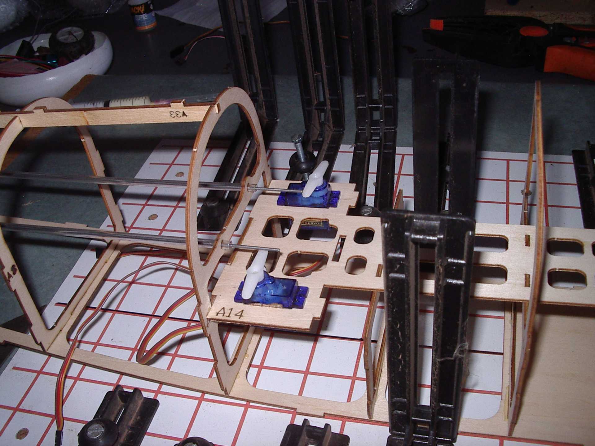
As you can see the sides are not on so I've been chewing on this problem for some time. The servo in the foreground is fitted as recommended. The servo in the background is fitted reversed and has much more clearance to the bulk head.

See fig 1.2
The carrier tube for the push rod is 3mm id and the rod itself is 1.5mm so there's a certain amount of 'wiggle' room for rod radial movement. Now I understand why Tim changed the system to 'pull pull'
Do it now, you may never get another chance
Please Log in or Create an account to join the conversation.