
- Posts: 757
- Thank you received: 1164
freeCAD and fuselage creation
- jon.in.swansea
-
 Topic Author
- Offline
- Elite Member
-

Less
More
14 Mar 2022 11:33 #31
by jon.in.swansea
Replied by jon.in.swansea on topic freeCAD and fuselage creation
Branching away from my pure-foam ARMIN wings I have printed out a set of ribs for a 150mm chord Clarke-Y with variants for the ends as well as to accept the pivots for the ailerons. The initial rib is a 25mm (to help with hold-down stresses) and the others ~50mm spacing.
I decided to redesign the spar to match the rib spacing. I toyed with adapting the rib to take a small compression spar but then opted for extending the spar and use 0.8mm plates each side to glue-join the spar (we shall see).

The trailing edge of the wing-at-aileron is a curved to match the pivot curve of the aileron. Once it sets I will remove the section of skewer at the aileron.

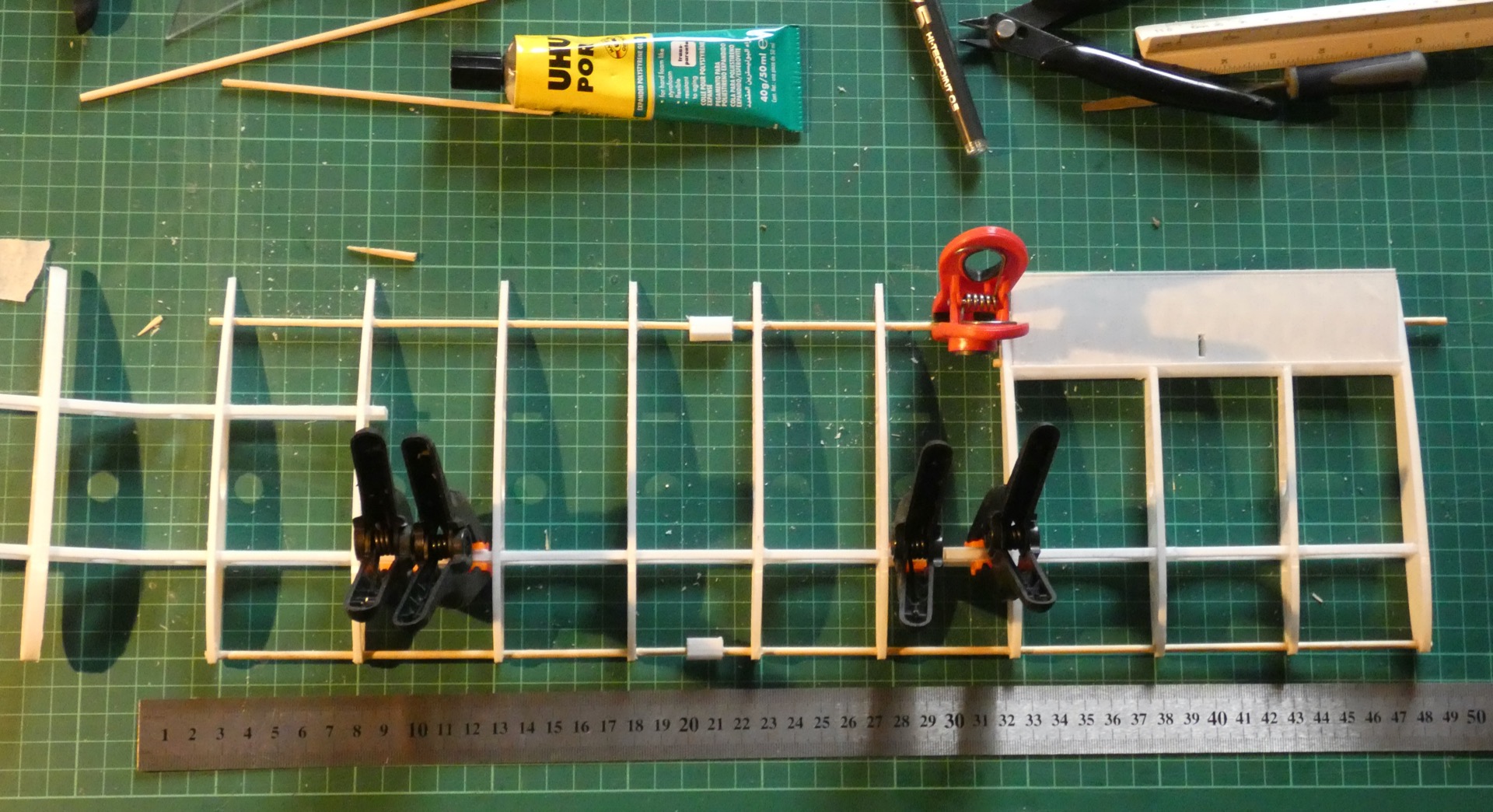
Last night I did the initial gluing around the aileron so that it would be stable while I adjusted the other ribs/spars/skewers. Below are the bits clamped in place.
Observation
a) The rear skewers are great for holding the ribs stable. The front skewers helped a bit but it turned out extending the spar made them a bit redundant.
b) An all-foam ARMIN is a 40 minute job from layout to attachment so it is an eye-opener for me the change in time building via ribs. Granted, I have probably made it more complex than necessary. I tend to invent wheels. I suspect there is a further hybrid design point that remove a bit of the complexity.
c) For ease of repair I might re-design the aileron for a tape hinge rather than use a pivot.
I decided to redesign the spar to match the rib spacing. I toyed with adapting the rib to take a small compression spar but then opted for extending the spar and use 0.8mm plates each side to glue-join the spar (we shall see).
The trailing edge of the wing-at-aileron is a curved to match the pivot curve of the aileron. Once it sets I will remove the section of skewer at the aileron.
Last night I did the initial gluing around the aileron so that it would be stable while I adjusted the other ribs/spars/skewers. Below are the bits clamped in place.
Observation
a) The rear skewers are great for holding the ribs stable. The front skewers helped a bit but it turned out extending the spar made them a bit redundant.
b) An all-foam ARMIN is a 40 minute job from layout to attachment so it is an eye-opener for me the change in time building via ribs. Granted, I have probably made it more complex than necessary. I tend to invent wheels. I suspect there is a further hybrid design point that remove a bit of the complexity.
c) For ease of repair I might re-design the aileron for a tape hinge rather than use a pivot.
Attachments:
Thanks: Quorneng
Please Log in or Create an account to join the conversation.
- Klipkopwildlife
-

- Offline
- Administrator
-

- I'm supposed to be retired!
14 Mar 2022 12:52 #32
by Klipkopwildlife
Do it now, you may never get another chance
Replied by Klipkopwildlife on topic freeCAD and fuselage creation
The time taken is the price of having an accurate wing which will give you many hours of joy. Considering you have ailerons I think the dihedral is about double what you actually need.
Do it now, you may never get another chance
Thanks: jon.in.swansea
Please Log in or Create an account to join the conversation.
- Eric
-

- Offline
- Moderator
-

Less
More
- Posts: 15406
- Thank you received: 14306
14 Mar 2022 14:13 - 14 Mar 2022 14:14 #33
by Eric
if you are calm and collected when all about you are going berserk - you've missed something important!
Replied by Eric on topic freeCAD and fuselage creation
That squared-off spar joint will be weak. A longer tapered scarf joint gives a much larger glue area.
As Tony put - too much dihedral for ailerons! One will fight the other at every turn command.
As Tony put - too much dihedral for ailerons! One will fight the other at every turn command.
if you are calm and collected when all about you are going berserk - you've missed something important!
Last edit: 14 Mar 2022 14:14 by Eric. Reason: added a comment
Thanks: Klipkopwildlife
Please Log in or Create an account to join the conversation.
- Quorneng
-

- Offline
- Forum Master
-

Less
More
- Posts: 10058
- Thank you received: 19043
14 Mar 2022 14:56 #34
by Quorneng
Replied by Quorneng on topic freeCAD and fuselage creation
jon
That all looks very impressive.
I presume the spar joiners go either side of the spar. It should be adequately strong but it does rely heavily on the glue strength at the top and bottom edges of the plate where the stress will be the greatest.
If it were me I would actually test a joint to see how it broke. Ideally it should not break at the joint at all but somewhere else along the spar.
That all looks very impressive.
I presume the spar joiners go either side of the spar. It should be adequately strong but it does rely heavily on the glue strength at the top and bottom edges of the plate where the stress will be the greatest.
If it were me I would actually test a joint to see how it broke. Ideally it should not break at the joint at all but somewhere else along the spar.
Thanks: Klipkopwildlife, jon.in.swansea
Please Log in or Create an account to join the conversation.
- jon.in.swansea
-
Topic Author
- Offline
- Elite Member
-
Less
More
- Posts: 757
- Thank you received: 1164
14 Mar 2022 18:20 #35
by jon.in.swansea
Replied by jon.in.swansea on topic freeCAD and fuselage creation
With a minor bit of sunk cost I could revise the dihedral brace to be ~4 degrees each side rather than 8. My current dihedral foam wing with 8 degrees each side has ailerons (granted not at the wing tip). It turns better than the rudder only version of several months ago. Perhaps I have gotten used to it. I could see what happens with this one and perhaps half the dihedral for the next go?
Please shout at me to make the change now if continuing is going to lead to a lot of pain.
Testing the joint - good idea. The central dihedral brace is quite strong. I could print another section glue it and see how it fails.
There is space before I cover to create additional 'U' shaped pieces to glue to the top and bottom of the join to give some extra resistance. -Jon
Please shout at me to make the change now if continuing is going to lead to a lot of pain.
Testing the joint - good idea. The central dihedral brace is quite strong. I could print another section glue it and see how it fails.
There is space before I cover to create additional 'U' shaped pieces to glue to the top and bottom of the join to give some extra resistance. -Jon
Thanks: Klipkopwildlife
Please Log in or Create an account to join the conversation.
- Klipkopwildlife
-
- Offline
- Administrator
-
- I'm supposed to be retired!
15 Mar 2022 06:59 #36
by Klipkopwildlife
Do it now, you may never get another chance
Replied by Klipkopwildlife on topic freeCAD and fuselage creation
Hi Jon, as Eric says, halve the dihedral.
Do it now, you may never get another chance
Thanks: jon.in.swansea
Please Log in or Create an account to join the conversation.
- jon.in.swansea
-
Topic Author
- Offline
- Elite Member
-
Less
More
- Posts: 757
- Thank you received: 1164
15 Mar 2022 09:08 #37
by jon.in.swansea
Replied by jon.in.swansea on topic freeCAD and fuselage creation
I have tweaked the main dihedral braces and am printing them out.... Unpicked some not quite set glue joints, will need to reprint one rib. Will remember scarf join for next design. -Jon
Thanks: Klipkopwildlife
Please Log in or Create an account to join the conversation.
- jon.in.swansea
-
Topic Author
- Offline
- Elite Member
-
Less
More
- Posts: 757
- Thank you received: 1164
19 Mar 2022 12:40 - 19 Mar 2022 12:45 #38
by jon.in.swansea
Replied by jon.in.swansea on topic freeCAD and fuselage creation
Quorneg speculated that the spar join might be the weak point. So I set up a test. Initially I tried a plate each side with UHU POR but after 18 hours it seemed easily deformed, indeed I could pull it apart with little effort. UHU needs far more surface area!
I cleaned up the spars, and plates and added a "U" piece for the top and bottom as seen below...

This time I used epoxy and gave it about 18 hours and I really had to work to break it.

That is what I have used for the main wing. Below all of the bits are in. I added some trays for the servos.
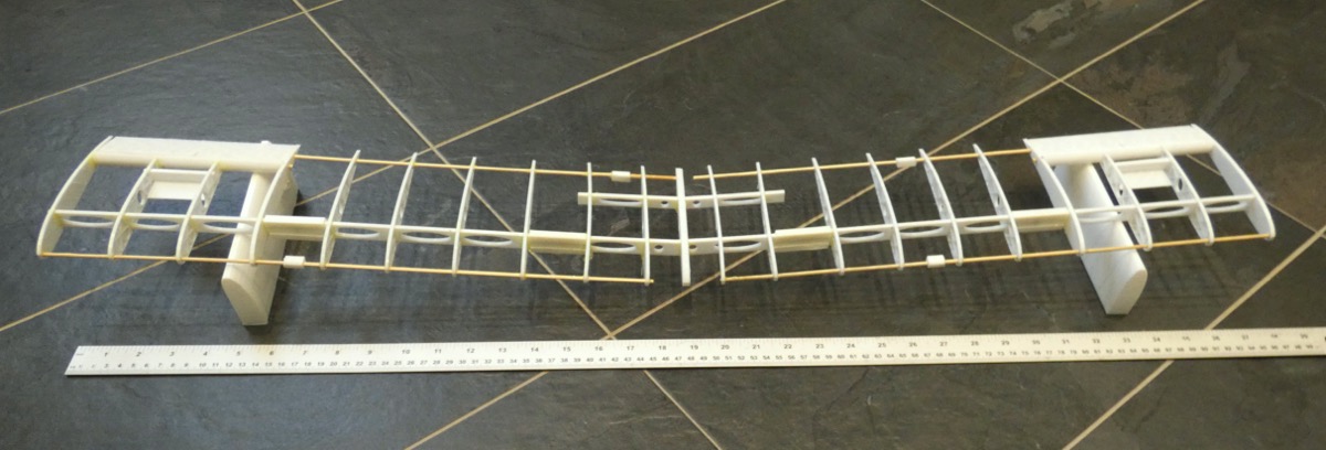
I notice looking at the centre section that the first ribs that I wanted to be ~25mm away from the centre are not quite the same - so much to review in the moments before the epoxy sets! This is outside my comfort zone and I know that subsequent prints and builds will lead to a new normal.
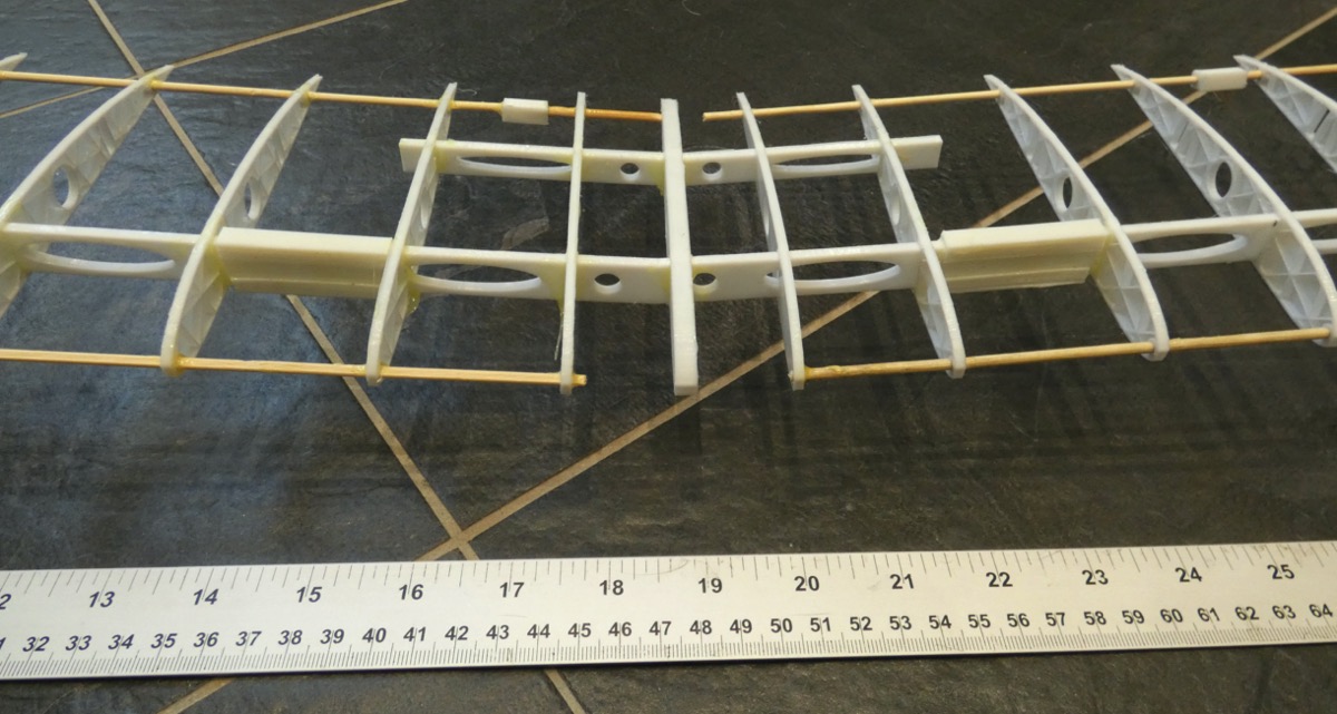
As seen it is 142g. If the foam is another 20-30g and 15-20g for servos and wiring that is ~190g for 165x960 and my ARMIN wing 900x180 is 177g (with wiring and servos). I would probably loose the leading edge skewers if I did it again but that is only ~5g.
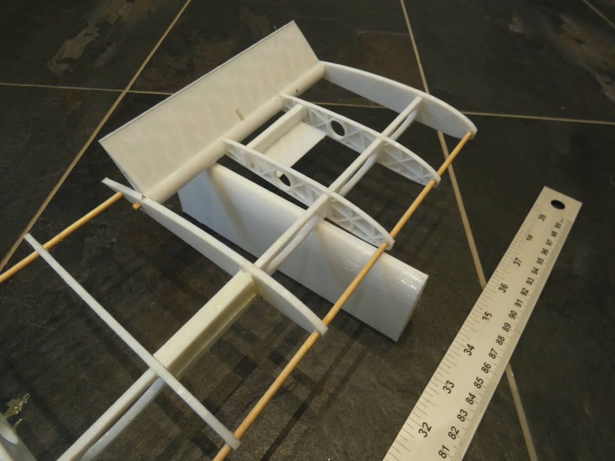
The printed ailerons are 8g each but I think they are lovely beasties as well as having a centre pivot which is different from a taped upper hinge point.
I cleaned up the spars, and plates and added a "U" piece for the top and bottom as seen below...
This time I used epoxy and gave it about 18 hours and I really had to work to break it.
That is what I have used for the main wing. Below all of the bits are in. I added some trays for the servos.
I notice looking at the centre section that the first ribs that I wanted to be ~25mm away from the centre are not quite the same - so much to review in the moments before the epoxy sets! This is outside my comfort zone and I know that subsequent prints and builds will lead to a new normal.
As seen it is 142g. If the foam is another 20-30g and 15-20g for servos and wiring that is ~190g for 165x960 and my ARMIN wing 900x180 is 177g (with wiring and servos). I would probably loose the leading edge skewers if I did it again but that is only ~5g.
The printed ailerons are 8g each but I think they are lovely beasties as well as having a centre pivot which is different from a taped upper hinge point.
Attachments:
Last edit: 19 Mar 2022 12:45 by jon.in.swansea.
Thanks: Klipkopwildlife, Quorneng
Please Log in or Create an account to join the conversation.
- Quorneng
-
- Offline
- Forum Master
-
Less
More
- Posts: 10058
- Thank you received: 19043
19 Mar 2022 17:35 #39
by Quorneng
Replied by Quorneng on topic freeCAD and fuselage creation
Your wing joint remedy certainly seems to have done the trick as far as the spar joins are concerned however there is still the question of a uniform spar section root to tip.
Are all the spar sections printed with the same structure?
If they are and the spar is strong enough at the root it will be many times too strong and thus heavier than necessary towards the tip. This is particularly so with a constant section 'plank' wing.
A simple test is to lift the complete with battery by just its wing tips. If it can you it will be adequately strong to fly and indeed it would be safe for moderate aerobatics like a gentle loop.
My printed spar wing had 5 "I" beam sections. The middle one had thick top and bottom flanges.
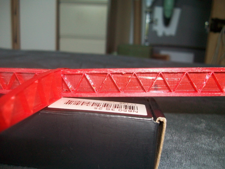
The tip section although of the same physical size had thin top and bottom flanges.

The spar sections were super glued together with a thin plate super glued over the top and bottom of the spar.
It did survive a rather alarming load test.

A centre load nearly twice the weight of the complete fuselage including battery is equivalent to pulling nearly 6g.
Even so I am pretty sure it will still eventually fail at the root!
As you have found out POR is not a particularly good 'high stress' glue. I have just pulled apart a large area POR glued printed joint that had been untouched for 5 years. The separation did not damage the printed surfaces in any way!
Are all the spar sections printed with the same structure?
If they are and the spar is strong enough at the root it will be many times too strong and thus heavier than necessary towards the tip. This is particularly so with a constant section 'plank' wing.
A simple test is to lift the complete with battery by just its wing tips. If it can you it will be adequately strong to fly and indeed it would be safe for moderate aerobatics like a gentle loop.
My printed spar wing had 5 "I" beam sections. The middle one had thick top and bottom flanges.
The tip section although of the same physical size had thin top and bottom flanges.
The spar sections were super glued together with a thin plate super glued over the top and bottom of the spar.
It did survive a rather alarming load test.
A centre load nearly twice the weight of the complete fuselage including battery is equivalent to pulling nearly 6g.
Even so I am pretty sure it will still eventually fail at the root!
As you have found out POR is not a particularly good 'high stress' glue. I have just pulled apart a large area POR glued printed joint that had been untouched for 5 years. The separation did not damage the printed surfaces in any way!
Attachments:
Thanks: Klipkopwildlife, jon.in.swansea
Please Log in or Create an account to join the conversation.
- jon.in.swansea
-
Topic Author
- Offline
- Elite Member
-
Less
More
- Posts: 757
- Thank you received: 1164
19 Mar 2022 18:52 - 19 Mar 2022 18:57 #40
by jon.in.swansea
Replied by jon.in.swansea on topic freeCAD and fuselage creation
Here is the end section of spar. I cut out ellipse between the ribs and away from the places where the glue plates would be fitted. The right edge is where I would glue it to the terminating rib that was adapted for the aileron. That gives fibres running at the top and bottom flange as well as along the ellipse. The failure happened when I added a twist. Other than slightly different locations for the ellipse it was thus the same section all along.

Essentially I had a rectangular shape that I subtracted ellipse shapes from. I printed them flat with 2 perimeters, 10% triangular file and 2 layers top and bottom. I wanted to be able to glue the side plates on to something substantial and had not though about only a top and bottom flange glue plate.
Your images are interesting with the varying depth of the flange. The rib printing with zero top layer I understand. I am puzzled how to get specific flange thickness as well as the exposed triangular infil. Ah! Unless you specified say 4 perimeters and that got you the additional flange thickness? -Jon
Essentially I had a rectangular shape that I subtracted ellipse shapes from. I printed them flat with 2 perimeters, 10% triangular file and 2 layers top and bottom. I wanted to be able to glue the side plates on to something substantial and had not though about only a top and bottom flange glue plate.
Your images are interesting with the varying depth of the flange. The rib printing with zero top layer I understand. I am puzzled how to get specific flange thickness as well as the exposed triangular infil. Ah! Unless you specified say 4 perimeters and that got you the additional flange thickness? -Jon
Attachments:
Last edit: 19 Mar 2022 18:57 by jon.in.swansea.
Thanks: Klipkopwildlife
Please Log in or Create an account to join the conversation.
- Quorneng
-
- Offline
- Forum Master
-
Less
More
- Posts: 10058
- Thank you received: 19043
19 Mar 2022 22:00 - 19 Mar 2022 22:01 #41
by Quorneng
Replied by Quorneng on topic freeCAD and fuselage creation
jon
In my case it is all done in CURA. The FreeCAD file for the spar is just a solid rectangle.

CURA was set to 1 bottom layer & zero top to give the single side. The wall count was set at 4 to give the thick flanges.

The structure between the walls is a 'grid' pattern infill with a density set to give the required pattern size. The infill Y axis was also adjusted so the pattern is in the desired position between the flanges.
The wall count is progressively reduced on each of the outer spar sections. The outer most section had a single wall.
The root spar section with thick flanges weighed 5g whereas the outer most with the same overall dimensions only weighed 2g.
In my case it is all done in CURA. The FreeCAD file for the spar is just a solid rectangle.
CURA was set to 1 bottom layer & zero top to give the single side. The wall count was set at 4 to give the thick flanges.
The structure between the walls is a 'grid' pattern infill with a density set to give the required pattern size. The infill Y axis was also adjusted so the pattern is in the desired position between the flanges.
The wall count is progressively reduced on each of the outer spar sections. The outer most section had a single wall.
The root spar section with thick flanges weighed 5g whereas the outer most with the same overall dimensions only weighed 2g.
Attachments:
Last edit: 19 Mar 2022 22:01 by Quorneng.
Thanks: Klipkopwildlife, jon.in.swansea
Please Log in or Create an account to join the conversation.
- Klipkopwildlife
-
- Offline
- Administrator
-
- I'm supposed to be retired!
20 Mar 2022 07:54 #42
by Klipkopwildlife
Do it now, you may never get another chance
Replied by Klipkopwildlife on topic freeCAD and fuselage creation
Thanks guys, I'm learning so much.
Do it now, you may never get another chance
Please Log in or Create an account to join the conversation.
- jon.in.swansea
-
Topic Author
- Offline
- Elite Member
-
Less
More
- Posts: 757
- Thank you received: 1164
26 Mar 2022 13:42 - 26 Mar 2022 13:49 #43
by jon.in.swansea
Replied by jon.in.swansea on topic freeCAD and fuselage creation
In building up the hybrid foam and printed ribs I am getting ideas about a 2nd iteration that is scaling to a smaller chord and span and incorporating more of the ideas that have come up in the forum. I took some images while working some of these ideas out. I rather do like the use of ellipses in smaller ribs. In the montage I focus on a 'C' clamp for spars. It does seem to be quite strong. -Jon

I see in the image a figure of 40% for the spar location - it is actually at 30%....
I see in the image a figure of 40% for the spar location - it is actually at 30%....
Attachments:
Last edit: 26 Mar 2022 13:49 by jon.in.swansea.
Thanks: Klipkopwildlife, Quorneng
Please Log in or Create an account to join the conversation.
- Quorneng
-
- Offline
- Forum Master
-
Less
More
- Posts: 10058
- Thank you received: 19043
26 Mar 2022 19:20 #44
by Quorneng
Replied by Quorneng on topic freeCAD and fuselage creation
jon
With a sheet foam covered wing is the lateral strength of the spar an issue?
It should be glued along its entire top and bottom length to the foam skin. All the foam has to do is to keep the spar straight and it will achieve its full vertical bending strength.
It all comes down to the glue strength.
With a sheet foam covered wing is the lateral strength of the spar an issue?
It should be glued along its entire top and bottom length to the foam skin. All the foam has to do is to keep the spar straight and it will achieve its full vertical bending strength.
It all comes down to the glue strength.
Thanks: Klipkopwildlife, jon.in.swansea
Please Log in or Create an account to join the conversation.
- jon.in.swansea
-
Topic Author
- Offline
- Elite Member
-
Less
More
- Posts: 757
- Thank you received: 1164
27 Mar 2022 08:57 #45
by jon.in.swansea
Replied by jon.in.swansea on topic freeCAD and fuselage creation
You are correct that lateral is a minor worry once the skin is in place. The printing with open top yielded a spar that is much less stiff laterally than earlier one with two layers top and bottom. It is, however, lighter in weight. Not having to design in the ellipse cut-outs to fit the rib spacing is a positive.
The hybrid foam and rib is a bit heavier than the all foam wing. For a first try it was a great learning experience. And the heat forming and slipping on the whole skin does seem to have worked - after the skin set I have started cutting away the excess around the ailerons and tidying up the ends and sanding the trailing edge.
There is a few mm gap at the front centre join of the skins and I haven't figured out how best to fill gaps in foam other than to cut some slivers and glue them in. With other scratch builds I might have used hot glue to fill.
The hybrid foam and rib is a bit heavier than the all foam wing. For a first try it was a great learning experience. And the heat forming and slipping on the whole skin does seem to have worked - after the skin set I have started cutting away the excess around the ailerons and tidying up the ends and sanding the trailing edge.
There is a few mm gap at the front centre join of the skins and I haven't figured out how best to fill gaps in foam other than to cut some slivers and glue them in. With other scratch builds I might have used hot glue to fill.
Please Log in or Create an account to join the conversation.
Time to create page: 0.326 seconds