
- Posts: 10058
- Thank you received: 19043
freeCAD and fuselage creation
- Quorneng
-

- Offline
- Forum Master
-

Less
More
27 Mar 2022 11:20 #46
by Quorneng
Replied by Quorneng on topic freeCAD and fuselage creation
jon
There is nothing wrong with filling gaps with foam slithers apart from being messy as you have to ensure there is a thin layer of glue over all the surfaces to be joined. If you are after a good surface any glue on the foam outer surface will leave a mark.
To my way of thinking using hot glue as a 'filler' rather negates the purpose of using foam in the first place.
The reasoning about lateral stiffness applies to ribs just as it does to the spar.
If you look at a full size rib it has very limted lateral stiffness and relies almost entirely on the skin even where that if fabric!

Not much lateral stiffness in this Sopwith rib!
There is nothing wrong with filling gaps with foam slithers apart from being messy as you have to ensure there is a thin layer of glue over all the surfaces to be joined. If you are after a good surface any glue on the foam outer surface will leave a mark.
To my way of thinking using hot glue as a 'filler' rather negates the purpose of using foam in the first place.
The reasoning about lateral stiffness applies to ribs just as it does to the spar.
If you look at a full size rib it has very limted lateral stiffness and relies almost entirely on the skin even where that if fabric!
Not much lateral stiffness in this Sopwith rib!
Attachments:
Thanks: Klipkopwildlife
Please Log in or Create an account to join the conversation.
- paul d
-
- Offline
- Forum Veteran
-

Less
More
- Posts: 2074
- Thank you received: 2292
27 Mar 2022 20:09 #47
by paul d
balsa is best.
Replied by paul d on topic freeCAD and fuselage creation
Must admit when I scratch build I make the ribs as light as possible, there only there to hold the profile shape, the spars, and leading edge give the strength. I agree with you Simon, adhesive is not suitable as a filler or substitute for a construction material.
balsa is best.
Thanks: Klipkopwildlife, jon.in.swansea
Please Log in or Create an account to join the conversation.
- jon.in.swansea
-
 Topic Author
- Offline
- Elite Member
-

Less
More
- Posts: 757
- Thank you received: 1164
18 Apr 2022 08:29 #48
by jon.in.swansea
Replied by jon.in.swansea on topic freeCAD and fuselage creation
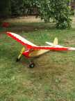
After some weeks of work tasks I got back to covering the 3D printed Clark-Y wing and getting it prepared for use. I took what I learned in the small scale test heat forming of 3mm foam and applied it to the left and right spans of the wing structure. I recorded the process (with fast forward in quite a few places) as well as testing the printed ailerons (I do like them) and then covering the top with yellow and with red-white on the lower surfaces.


The video of the heat forming is here. Might show up better on YouTube rather than on aeromodellers.
The completed wing 155mm chord and 960mm span is 250g - a bit more than I was hoping for. It does seem robust so I am imaging several of Simon's ideas to lighten it up in future iterations. I am going for a ~105mm chord x 700 span with 4 deg dihedral and tip ailerons in my next wing with the aim of greater portability.

Here is the wing in place on my Franken Pod. All up for flight it is a bit over 500g.
Actually, part of the reason I went slow on this is the time it took to put it together. I was worried about what might happen in a rough landing. I did go out on Saturday. I thought it was calm but on arrival the wind was building up considerably and although I did a couple of test glides I concluded that it just wasn't suitable for an untested combination.
I did a maiden flight in the park Sunday morning. Little wind. at 500g with a 650mAhr 3 cell it felt a bit heavy but once launched I set about some figure eights to get a feel for the beastie. The end placement of the ailerons seemed to work and it was happy to run along at 1/3 to 1/2 throttle. It seemed better at slower speeds than the previous wing.
I set the COG at a few mm aft of 30%. I need more flights to determine if that is a good choice. And I still have to check out its glide performance and establish its most comfortable landing pattern. If I could get that 50g to 100g off that I think it would make a sweet slow flyer.
As to its robustness, I caught a wing tip on landing but the cartwheel seemed to have not bothered the wing although I later found one of the aileron connectors had gone out of alignment.
I did film it but later found that the camera had shifted in the head mount and I didn't actually capture any of the flight .
.
The video of the heat forming is here. Might show up better on YouTube rather than on aeromodellers.
The completed wing 155mm chord and 960mm span is 250g - a bit more than I was hoping for. It does seem robust so I am imaging several of Simon's ideas to lighten it up in future iterations. I am going for a ~105mm chord x 700 span with 4 deg dihedral and tip ailerons in my next wing with the aim of greater portability.
Here is the wing in place on my Franken Pod. All up for flight it is a bit over 500g.
Actually, part of the reason I went slow on this is the time it took to put it together. I was worried about what might happen in a rough landing. I did go out on Saturday. I thought it was calm but on arrival the wind was building up considerably and although I did a couple of test glides I concluded that it just wasn't suitable for an untested combination.
I did a maiden flight in the park Sunday morning. Little wind. at 500g with a 650mAhr 3 cell it felt a bit heavy but once launched I set about some figure eights to get a feel for the beastie. The end placement of the ailerons seemed to work and it was happy to run along at 1/3 to 1/2 throttle. It seemed better at slower speeds than the previous wing.
I set the COG at a few mm aft of 30%. I need more flights to determine if that is a good choice. And I still have to check out its glide performance and establish its most comfortable landing pattern. If I could get that 50g to 100g off that I think it would make a sweet slow flyer.
As to its robustness, I caught a wing tip on landing but the cartwheel seemed to have not bothered the wing although I later found one of the aileron connectors had gone out of alignment.
I did film it but later found that the camera had shifted in the head mount and I didn't actually capture any of the flight
. Attachments:
Thanks: Klipkopwildlife, THE BLACKBIRD
Please Log in or Create an account to join the conversation.
- Quorneng
-
- Offline
- Forum Master
-
Less
More
- Posts: 10058
- Thank you received: 19043
18 Apr 2022 10:34 #49
by Quorneng
Replied by Quorneng on topic freeCAD and fuselage creation
jon
That wing looks very nice just right for the Franken Pod. Hopefully there will be a video of it flying although I know all about finding out there is nothing to see!
The video of the skin forming is also very interesting and I recognised that 'crack' sound instantly which brings me on to the benefit of doing it.
If you consider tor the radii involved in the shape of a Clark Y rib, or virtually any other come to that, they are all pretty gentle except for a very small section at the 'nose' where the radii are whole orders sharper than the rest. It was this fact that steered me towards the individual top and bottom skin approach with an added but shaped nose section.
Done this way the bends required are well within the capability of the sheet foam such that only 'cold forming' might be necessary if at all.
Quite some time ago I made this short video of cold forming a piece of 3 mm Depron.
I still use this method. The object is to arrange that the formed skin follows follows the profile of the rib closely enough that only a small additional weight is required to ensure complete contact between the skin and the ribs.
I would also agree entirely with your wish to loose up to 100g to create a true slow flier.
My similar printed rib, Depron skin wing is a bit bigger at 1300mm x 200 mm but only weighs 145 g yet is still strong enough to be used on a plane that weighs 743g.
That wing looks very nice just right for the Franken Pod. Hopefully there will be a video of it flying although I know all about finding out there is nothing to see!
The video of the skin forming is also very interesting and I recognised that 'crack' sound instantly
which brings me on to the benefit of doing it.If you consider tor the radii involved in the shape of a Clark Y rib, or virtually any other come to that, they are all pretty gentle except for a very small section at the 'nose' where the radii are whole orders sharper than the rest. It was this fact that steered me towards the individual top and bottom skin approach with an added but shaped nose section.
Done this way the bends required are well within the capability of the sheet foam such that only 'cold forming' might be necessary if at all.
Quite some time ago I made this short video of cold forming a piece of 3 mm Depron.
I still use this method. The object is to arrange that the formed skin follows follows the profile of the rib closely enough that only a small additional weight is required to ensure complete contact between the skin and the ribs.
I would also agree entirely with your wish to loose up to 100g to create a true slow flier.
My similar printed rib, Depron skin wing is a bit bigger at 1300mm x 200 mm but only weighs 145 g yet is still strong enough to be used on a plane that weighs 743g.
Thanks: Klipkopwildlife, jon.in.swansea
Please Log in or Create an account to join the conversation.
- Klipkopwildlife
-

- Offline
- Administrator
-

- I'm supposed to be retired!
18 Apr 2022 11:01 #50
by Klipkopwildlife
Do it now, you may never get another chance
Replied by Klipkopwildlife on topic freeCAD and fuselage creation
That's great Jon, one of the reasons you're seeing better low speed performance is that, at close to stall speeds the centre of pressure doesn't move very much compared to some airfoil shapes. The fact that the Clark Y has been around for some 80 years and is still the foil of choice for many applications bears testament to its forgiving nature.
Do it now, you may never get another chance
Thanks: jon.in.swansea
Please Log in or Create an account to join the conversation.
- jon.in.swansea
-
Topic Author
- Offline
- Elite Member
-
Less
More
- Posts: 757
- Thank you received: 1164
19 Apr 2022 09:13 #51
by jon.in.swansea
Replied by jon.in.swansea on topic freeCAD and fuselage creation
One of my frustrations with putting together the Clarke-Y wing structure was the fiddly end-of-wing aileron support. The curved brace just in front of the aileron in particular - even at the scale of a 150mm chord. My next planed wing is for a 105mm chord and so the bits would be even more fiddly.
One thing I had not tried in freeCAD was to combine a number of complex bodies. So to learn more about how to do that a project sorting the end-of-wing at the smaller scale seemed a worthwhile project. Below is a view of the CAD model.

Essentially I took the sketch of the rib and duplicated and transformed. I copied the object for the curved brace from another file and added that and then inserted block shapes for the spar (extending to one side to accept a glued brace to the adjacent bit of spar). Below is a photo of the junction where the aileron will be inserted.

The magic of 3D printing allows one to take a part and mirror it (within the slicer software for the printer). In the image below are the two mirrored ends with the centre spar. What remains is to decide the length of the intermediate spars and how many ribs. I space the ribs at 60mm in the end sections (I had used ~50mm in the 150mm chord structure) and I might continue with a 60mm spacing except for where the rubber bands will be.

I then extruded the aileron from the trailing section of the rib, measured the gap and printed a pair. I then inserted a short section of tube to act as support/hinge at each end and attached the ailerons. They pivot nicely. Rather than guess in advance the specific location of the horns I will glue them on once I sort out the specific position of the servos.
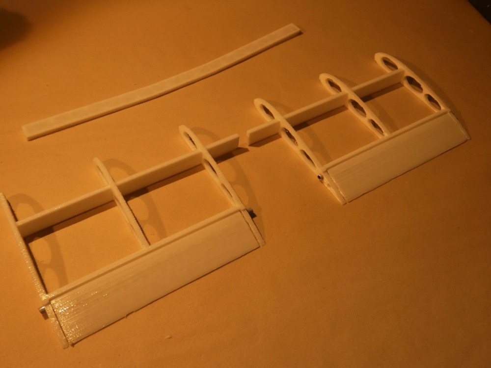
Pros: other than some post finishing to remove a few printing supports there is certainly less fiddle. It is stiffer in all axis then gluing a half dozen bits together. It avoids the need to figure out how to brace parts while epoxy sets up.
Cons: the print orientation resulted in solid sides so a bit extra weight there. Each end, including the aileron comes in at 20g. If I could have been bothered to craft a one-sided webbed spar I could have shaved a few g. I printed the aileron with 2 layers top/bottom and sides and 10% infil and base of aileron on the bed. Previously I printed vertical with a single perimeter and I might try a reprint to see if that can also save a few g.
It has been an interesting learning process. -Jon
One thing I had not tried in freeCAD was to combine a number of complex bodies. So to learn more about how to do that a project sorting the end-of-wing at the smaller scale seemed a worthwhile project. Below is a view of the CAD model.
Essentially I took the sketch of the rib and duplicated and transformed. I copied the object for the curved brace from another file and added that and then inserted block shapes for the spar (extending to one side to accept a glued brace to the adjacent bit of spar). Below is a photo of the junction where the aileron will be inserted.
The magic of 3D printing allows one to take a part and mirror it (within the slicer software for the printer). In the image below are the two mirrored ends with the centre spar. What remains is to decide the length of the intermediate spars and how many ribs. I space the ribs at 60mm in the end sections (I had used ~50mm in the 150mm chord structure) and I might continue with a 60mm spacing except for where the rubber bands will be.
I then extruded the aileron from the trailing section of the rib, measured the gap and printed a pair. I then inserted a short section of tube to act as support/hinge at each end and attached the ailerons. They pivot nicely. Rather than guess in advance the specific location of the horns I will glue them on once I sort out the specific position of the servos.
Pros: other than some post finishing to remove a few printing supports there is certainly less fiddle. It is stiffer in all axis then gluing a half dozen bits together. It avoids the need to figure out how to brace parts while epoxy sets up.
Cons: the print orientation resulted in solid sides so a bit extra weight there. Each end, including the aileron comes in at 20g. If I could have been bothered to craft a one-sided webbed spar I could have shaved a few g. I printed the aileron with 2 layers top/bottom and sides and 10% infil and base of aileron on the bed. Previously I printed vertical with a single perimeter and I might try a reprint to see if that can also save a few g.
It has been an interesting learning process. -Jon
Attachments:
Thanks: Klipkopwildlife, Quorneng, THE BLACKBIRD
Please Log in or Create an account to join the conversation.
- Klipkopwildlife
-
- Offline
- Administrator
-
- I'm supposed to be retired!
19 Apr 2022 10:49 #52
by Klipkopwildlife
Do it now, you may never get another chance
Replied by Klipkopwildlife on topic freeCAD and fuselage creation
Nice going Jon, I can't wait to get back to actually doing something on my printer.
Do it now, you may never get another chance
Thanks: jon.in.swansea
Please Log in or Create an account to join the conversation.
- Eric
-

- Offline
- Moderator
-

Less
More
- Posts: 15406
- Thank you received: 14306
19 Apr 2022 13:13 - 19 Apr 2022 13:15 #53
by Eric
if you are calm and collected when all about you are going berserk - you've missed something important!
Replied by Eric on topic freeCAD and fuselage creation
Where to mount the control horns - generally in the spanwise centre of the control surface, to reduce the likelihood of twisting under air pressure.
As you have a rib there, you can offset the servo very slightly, and use the rib as part of the mounting block.
As you have a rib there, you can offset the servo very slightly, and use the rib as part of the mounting block.
if you are calm and collected when all about you are going berserk - you've missed something important!
Last edit: 19 Apr 2022 13:15 by Eric. Reason: added a word
Thanks: Klipkopwildlife, jon.in.swansea
Please Log in or Create an account to join the conversation.
- Quorneng
-
- Offline
- Forum Master
-
Less
More
- Posts: 10058
- Thank you received: 19043
19 Apr 2022 18:24 #54
by Quorneng
Replied by Quorneng on topic freeCAD and fuselage creation
jon
You certainly seem to have got the hang of printing complex structures but the down side is you can end up using a lot of filament with a resulting weight pernalty.
As an example your wing tip has the look of a classic balsa structure that might be covered with a film skin which provides absolutely no compressive strength.
On the other hand a relatively thick foam skin covering provides both compressive and tensile strength.
The problem is 3D print filament has characteristics that are very different to a polystyrene foam with at least 5 times the density and about 10 times the stiffness. It follows that combining printed elements directly with foam can be structurally inefficient unless the printed components are used in locations where its beneficial structural properties outweigh any weight penalty.
Such applications in an model plane airframe are quite hard to find.
You certainly seem to have got the hang of printing complex structures but the down side is you can end up using a lot of filament with a resulting weight pernalty.
As an example your wing tip has the look of a classic balsa structure that might be covered with a film skin which provides absolutely no compressive strength.
On the other hand a relatively thick foam skin covering provides both compressive and tensile strength.
The problem is 3D print filament has characteristics that are very different to a polystyrene foam with at least 5 times the density and about 10 times the stiffness. It follows that combining printed elements directly with foam can be structurally inefficient unless the printed components are used in locations where its beneficial structural properties outweigh any weight penalty.
Such applications in an model plane airframe are quite hard to find.
Thanks: Klipkopwildlife, jon.in.swansea
Please Log in or Create an account to join the conversation.
- jon.in.swansea
-
Topic Author
- Offline
- Elite Member
-
Less
More
- Posts: 757
- Thank you received: 1164
19 Apr 2022 19:08 #55
by jon.in.swansea
Replied by jon.in.swansea on topic freeCAD and fuselage creation
I take your point. It is an iterative process. Some stuff gets noticed in the CAD tool, some in the slicer 'preview' and then when you are holding the real beastie in your hands you notice even more stuff.
At least with a small (albeit complex) object it is possible to explore alternatives and observe at those three points in the process if the revisions are helping. At least one can quickly preview and get a print time and weight without the actual print being carried out. -Jon
At least with a small (albeit complex) object it is possible to explore alternatives and observe at those three points in the process if the revisions are helping. At least one can quickly preview and get a print time and weight without the actual print being carried out. -Jon
Thanks: THE BLACKBIRD
Please Log in or Create an account to join the conversation.
- Klipkopwildlife
-
- Offline
- Administrator
-
- I'm supposed to be retired!
20 Apr 2022 08:28 #56
by Klipkopwildlife
Do it now, you may never get another chance
Replied by Klipkopwildlife on topic freeCAD and fuselage creation
Has anyone tried this new Light Weight filament? My understanding is, the higher the extrusion temperature, the lighter the printed part.
Do it now, you may never get another chance
Please Log in or Create an account to join the conversation.
- Quorneng
-
- Offline
- Forum Master
-
Less
More
- Posts: 10058
- Thank you received: 19043
20 Apr 2022 22:51 #57
by Quorneng
Replied by Quorneng on topic freeCAD and fuselage creation
Not yet but it is on my to do list.
Eclipson who have designed some printed planes and sell the STL files actually suggest using LW PLA to give a 20+% overall weight saving. They even suggest that when using LW PLA the wing needs no carbon reinforcing!
The degree of foaming generated is controlled by the extruding temperature. Maximum foaming occurs at 240 C. It is noted that working continually at such a temperature is beyond the capability of a PTFE guide tube so it requires a specific high temperature set up.
I do suspect a 'foaming' filament will become the norm for printed planes.
Eclipson who have designed some printed planes and sell the STL files actually suggest using LW PLA to give a 20+% overall weight saving. They even suggest that when using LW PLA the wing needs no carbon reinforcing!
The degree of foaming generated is controlled by the extruding temperature. Maximum foaming occurs at 240 C. It is noted that working continually at such a temperature is beyond the capability of a PTFE guide tube so it requires a specific high temperature set up.
I do suspect a 'foaming' filament will become the norm for printed planes.
Thanks: Klipkopwildlife
Please Log in or Create an account to join the conversation.
- jon.in.swansea
-
Topic Author
- Offline
- Elite Member
-
Less
More
- Posts: 757
- Thank you received: 1164
22 Apr 2022 15:58 #58
by jon.in.swansea
Replied by jon.in.swansea on topic freeCAD and fuselage creation
2nd revision to a printed Clarke-Y wing end with integrated aileron....
My prior printing of a 105mm chord end assembly came out at 21g per end. I revisited the design while waiting for the winds to die down.
Here is the original with 3 ribs, aileron in place and with a stub spar to join with the rest of the wing.

One option was to look at the printing parameters, the aileron was 9g printed flat with 2 layers top and bottom and 2 perimeters. I printed it again vertical with 1 perimeter and saved 1g.
The spar is stronger than it needs to be so I cut some ovals, went from 2 perimeters to 1 perimeters and 5% fill. I found the ovals would print without any 'supports'. Good. But a 0.2mm layer height yields a ragged top curve so I opted for 0.15mm layer heights - took longer but less work needed to smooth it out to give a better attachment for the foam.

The result is 16g for the assembled end so a pair will save me 10g overall.

-Jon
My prior printing of a 105mm chord end assembly came out at 21g per end. I revisited the design while waiting for the winds to die down.
Here is the original with 3 ribs, aileron in place and with a stub spar to join with the rest of the wing.
One option was to look at the printing parameters, the aileron was 9g printed flat with 2 layers top and bottom and 2 perimeters. I printed it again vertical with 1 perimeter and saved 1g.
The spar is stronger than it needs to be so I cut some ovals, went from 2 perimeters to 1 perimeters and 5% fill. I found the ovals would print without any 'supports'. Good. But a 0.2mm layer height yields a ragged top curve so I opted for 0.15mm layer heights - took longer but less work needed to smooth it out to give a better attachment for the foam.
The result is 16g for the assembled end so a pair will save me 10g overall.
-Jon
Attachments:
Thanks: Klipkopwildlife, Quorneng
Please Log in or Create an account to join the conversation.
- jon.in.swansea
-
Topic Author
- Offline
- Elite Member
-
Less
More
- Posts: 757
- Thank you received: 1164
09 May 2022 12:27 #59
by jon.in.swansea
Replied by jon.in.swansea on topic freeCAD and fuselage creation
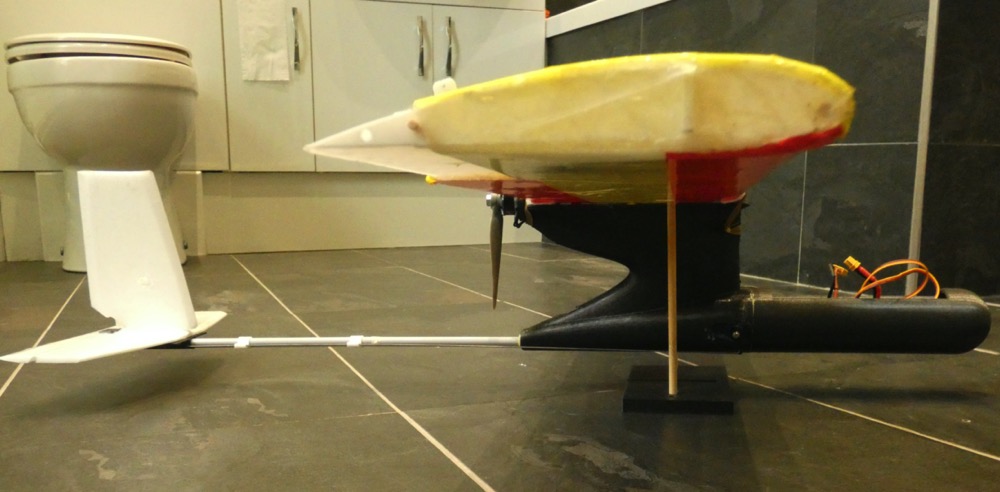
After popping the pylon on my pusher Franken Pod I decided it was time to make use of my smaller scale derivitive of Simon's printed pusher. With the new Clarke-Y wing it comes in at 580g (80 more than the Franken Pod). It has
* flight test radial 1806 2280kv and an APC 7x4.5 with ~20mm clearance to the boom.
* 650mAhr 3 cell
*span 960mm cord 155mm. ~4 degrees of dihedral
* elevator servo in fuselage (properly oriented new micro this time).
* tail assembly starts 300mm aft of the trailing edge.
* printed pod 370mm long, overall length 730mm (not yet fixed I might reduce ~10mm)
* COG 45mm back with a 2p coin in the nose.
I anticipate needing to keep it above 50% throttle if it is anything like my prior pushers. I have a 2205 motor that I might swop in if it proves critically underpowered. There is physical space for an 8" prop but that will probably be pushing the motor.
Ideally I would like the model 50-80g lighter. The diameter of the fuselage is, perhaps a bit larger than needed and less clearance at the prop would be possible. That said - moving to a 105mm chord and ~700mm span Clarke-Y and scaling the whole print down is what I think I will do it will be easier to carry around and perhaps have a better weight to power.
Below are some images. It would be GREAT to get comments before I go further. -Jon


* flight test radial 1806 2280kv and an APC 7x4.5 with ~20mm clearance to the boom.
* 650mAhr 3 cell
*span 960mm cord 155mm. ~4 degrees of dihedral
* elevator servo in fuselage (properly oriented new micro this time).
* tail assembly starts 300mm aft of the trailing edge.
* printed pod 370mm long, overall length 730mm (not yet fixed I might reduce ~10mm)
* COG 45mm back with a 2p coin in the nose.
I anticipate needing to keep it above 50% throttle if it is anything like my prior pushers. I have a 2205 motor that I might swop in if it proves critically underpowered. There is physical space for an 8" prop but that will probably be pushing the motor.
Ideally I would like the model 50-80g lighter. The diameter of the fuselage is, perhaps a bit larger than needed and less clearance at the prop would be possible. That said - moving to a 105mm chord and ~700mm span Clarke-Y and scaling the whole print down is what I think I will do it will be easier to carry around and perhaps have a better weight to power.
Below are some images. It would be GREAT to get comments before I go further. -Jon
Attachments:
Thanks: Klipkopwildlife, THE BLACKBIRD
Please Log in or Create an account to join the conversation.
- Quorneng
-
- Offline
- Forum Master
-
Less
More
- Posts: 10058
- Thank you received: 19043
09 May 2022 15:31 - 09 May 2022 15:38 #60
by Quorneng
Replied by Quorneng on topic freeCAD and fuselage creation
It certainly looks a very "tidy" plane with perfectly reasonable proportions. I am sure it will fly nicely if you get the CofG something like right.
If I have a concern it is its weight or more accurately its power to weight with a concerquence to the wing loading.
My nearest comparable pusher, the Blue Dragon, has a span of 1120 mm and a mean chord of 155 mm giving 16% more wing area. I also suspect it has a somewhat 'thinner' Clark Y section of 20 mm maximum depth at the mean chord.

The biggest difference will be its power and weight.
It has 150W 1500kV motor (Emax 2812) driving a 7x6 and a 1500 mAh 3s battery with a 30A ESC yet it weighs only 453g or just 78% of your plane. This means it has a wing loading that is only 52% coupled with 1.3 times the power and over twice the battery capacity.
You can see where these figures are pointing. It will be able to fly somewhat slower using less power yet have plenty of 'spare' to climb rapidly or just to fly faster. For normal flying none of the electrics are highly stressed
The power to fly and particularly to climb is directly proportional to the plane's weight. On this basis if you could 'loose' say 50g but keeping the same overall dimensions you would have quite a bit more spare power.
Lastly I do wonder for that motor if a 7x4.5 is really intended for use with a 2s battery. A 6x4 is considerd best suited for 3s operation.
The recommended props for a virtually identical motor.

If I have a concern it is its weight or more accurately its power to weight with a concerquence to the wing loading.
My nearest comparable pusher, the Blue Dragon, has a span of 1120 mm and a mean chord of 155 mm giving 16% more wing area. I also suspect it has a somewhat 'thinner' Clark Y section of 20 mm maximum depth at the mean chord.
The biggest difference will be its power and weight.
It has 150W 1500kV motor (Emax 2812) driving a 7x6 and a 1500 mAh 3s battery with a 30A ESC yet it weighs only 453g or just 78% of your plane. This means it has a wing loading that is only 52% coupled with 1.3 times the power and over twice the battery capacity.
You can see where these figures are pointing. It will be able to fly somewhat slower using less power yet have plenty of 'spare' to climb rapidly or just to fly faster. For normal flying none of the electrics are highly stressed
The power to fly and particularly to climb is directly proportional to the plane's weight. On this basis if you could 'loose' say 50g but keeping the same overall dimensions you would have quite a bit more spare power.
Lastly I do wonder for that motor if a 7x4.5 is really intended for use with a 2s battery. A 6x4 is considerd best suited for 3s operation.
The recommended props for a virtually identical motor.
Attachments:
Last edit: 09 May 2022 15:38 by Quorneng.
Thanks: Klipkopwildlife, jon.in.swansea
Please Log in or Create an account to join the conversation.
Time to create page: 0.524 seconds