
- Posts: 10058
- Thank you received: 19043
Folland Gnat T1
- Quorneng
-
 Topic Author
- Offline
- Forum Master
-

Less
More
03 Jan 2020 00:12 - 03 Jan 2020 00:16 #1
by Quorneng
Folland Gnat T1 was created by Quorneng
On the RCME site Tony Nijhuis has been describing his 'Mini Jet series' which includes the Sabre, Hunter, Gnat and Jet Provost.
The plain turbojet used in all these planes, particularly the JP, only requires the inlet area to be about 0.8 of the jet pipe area. Not a good combination for an EDF where the whole inlet duct ideally wants a cross section to be something like 1.4 times the area of the jet pipe.
The popular solution is to 'stretch' the inlets dimensions without distorting the appearance to much, use cheat holes and a powerful fan to overcome the inevitable losses.
The Tony Nijhuis designs use the FMS 50 mm 11 blade fan that requires a substantial 32 A to deliver 350 W on a 3s. The planes certainly seem to fly well but it has been noted by several builders that increasing the size of the cheat hole significantly improves the performance.
Whilst this approach works it does rather 'annoy' the engineering in me as well as my 'OCD' concerning weight. I started wondering if there was a better solution and keep the inlets true scale.
To do this requires that the plane is sized so that true scale inlets are sufficiently big to efficiently feed the chosen EDF. This suggest the plane is likely to be a bit larger than the TN design, however at this size if the EDF is placed within the fuselage and the exhaust tube area is set to be 85% of the fan swept area for maximum thrust the visible jet 'pipe' will be considerably under scale diameter. At least it will not impact the scale rear end of the fuselage.
This further suggest there is some scale advantage in putting the EDF 'right at the back' as the EDF casing will be nearer to the scale jet pipe diameter. I believe there are also some duct efficiencies to be gained by doing this.
This a path I have trodden before with my Fairey Delta 2 which had exactly the same inlet versus exhaust area problem. It also used the EDF 'right at the back' solution to allow both scale inlets and a near scale diameter jet pipe.
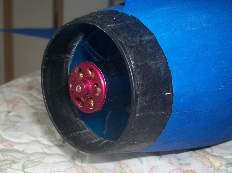
Of course as a delta it does have substantial wing area and being all Depron it managed with a modest relatively low power 55 mm EDF.
I just happen to have an unused 50 mm EDF. On a 3s it only generates 2/3 the thrust of the FMS unit used by TN but then it only requires 2/3 the amps and is 2/3 the weight.
Still just 'thinking' at this stage.
The plain turbojet used in all these planes, particularly the JP, only requires the inlet area to be about 0.8 of the jet pipe area. Not a good combination for an EDF where the whole inlet duct ideally wants a cross section to be something like 1.4 times the area of the jet pipe.
The popular solution is to 'stretch' the inlets dimensions without distorting the appearance to much, use cheat holes and a powerful fan to overcome the inevitable losses.
The Tony Nijhuis designs use the FMS 50 mm 11 blade fan that requires a substantial 32 A to deliver 350 W on a 3s. The planes certainly seem to fly well but it has been noted by several builders that increasing the size of the cheat hole significantly improves the performance.
Whilst this approach works it does rather 'annoy' the engineering in me as well as my 'OCD' concerning weight. I started wondering if there was a better solution and keep the inlets true scale.
To do this requires that the plane is sized so that true scale inlets are sufficiently big to efficiently feed the chosen EDF. This suggest the plane is likely to be a bit larger than the TN design, however at this size if the EDF is placed within the fuselage and the exhaust tube area is set to be 85% of the fan swept area for maximum thrust the visible jet 'pipe' will be considerably under scale diameter. At least it will not impact the scale rear end of the fuselage.
This further suggest there is some scale advantage in putting the EDF 'right at the back' as the EDF casing will be nearer to the scale jet pipe diameter. I believe there are also some duct efficiencies to be gained by doing this.
This a path I have trodden before with my Fairey Delta 2 which had exactly the same inlet versus exhaust area problem. It also used the EDF 'right at the back' solution to allow both scale inlets and a near scale diameter jet pipe.
Of course as a delta it does have substantial wing area and being all Depron it managed with a modest relatively low power 55 mm EDF.
I just happen to have an unused 50 mm EDF. On a 3s it only generates 2/3 the thrust of the FMS unit used by TN but then it only requires 2/3 the amps and is 2/3 the weight.
Still just 'thinking' at this stage.
Last edit: 03 Jan 2020 00:16 by Quorneng.
Thanks: Phil Wood, Eric, Klipkopwildlife, crash happy
Please Log in or Create an account to join the conversation.
- Quorneng
-
Topic Author
- Offline
- Forum Master
-
Less
More
- Posts: 10058
- Thank you received: 19043
03 Jan 2020 19:30 - 03 Jan 2020 19:31 #2
by Quorneng
Replied by Quorneng on topic Folland Gnat T1
A bifurcated duct for an EDF is always a bit fiddly so I wondered if it could be printed with a bit of 'offset' printing.
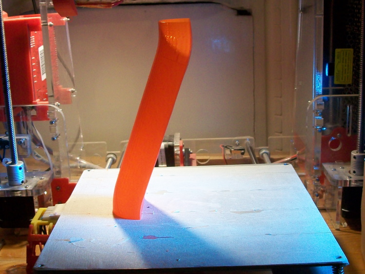
Amazed it held down.
Left and right are of course identical so you just print two and glue them together.
The test is to see if the complete duct can be printed, glued together to the EDF and then use it as a 'spine' to build the fuselage around it.
It might work!
Amazed it held down.
Left and right are of course identical so you just print two and glue them together.
The test is to see if the complete duct can be printed, glued together to the EDF and then use it as a 'spine' to build the fuselage around it.
It might work!
Last edit: 03 Jan 2020 19:31 by Quorneng.
Thanks: Phil Wood, Klipkopwildlife, crash happy
Please Log in or Create an account to join the conversation.
- Quorneng
-
Topic Author
- Offline
- Forum Master
-
Less
More
- Posts: 10058
- Thank you received: 19043
04 Jan 2020 19:16 - 04 Jan 2020 19:18 #3
by Quorneng
Replied by Quorneng on topic Folland Gnat T1
If you choose an EDF that can tolerate scale size inlets it tends to be small for the size of the plane so the duct ends up rather long and spindly looking something like this.
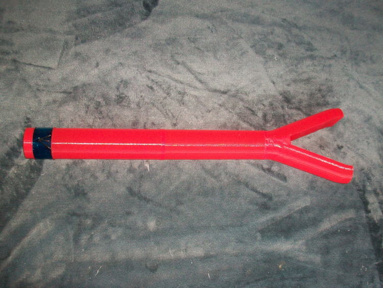
With the EDF "right at the back" the inlet may be long but the thrust tube is virtually non existent.

To make the bifurcate easier to print each branch is semicircular.

It would need a short 'make up' piece to alter the duct cross section of each branch to match the actual inlet shape.
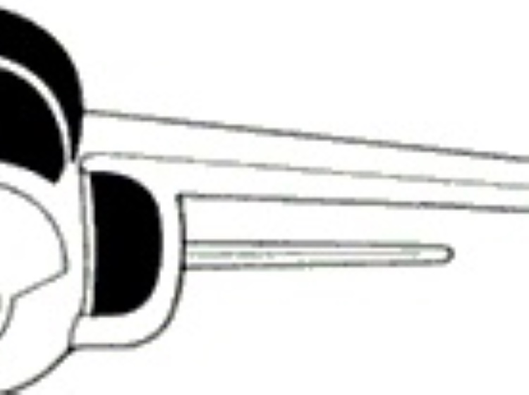
Before going any further some testing will be required to establish the effect the ducting has on the EDF's thrust.
Its a good a way as any to pass the time on long winter evenings.
With the EDF "right at the back" the inlet may be long but the thrust tube is virtually non existent.
To make the bifurcate easier to print each branch is semicircular.
It would need a short 'make up' piece to alter the duct cross section of each branch to match the actual inlet shape.
Before going any further some testing will be required to establish the effect the ducting has on the EDF's thrust.
Its a good a way as any to pass the time on long winter evenings.
Last edit: 04 Jan 2020 19:18 by Quorneng.
Thanks: Phil Wood, Klipkopwildlife, Flytilbroke, Ralpharr2001, crash happy
Please Log in or Create an account to join the conversation.
- Quorneng
-
Topic Author
- Offline
- Forum Master
-
Less
More
- Posts: 10058
- Thank you received: 19043
05 Jan 2020 23:53 #4
by Quorneng
Replied by Quorneng on topic Folland Gnat T1
Just a bit of testing.
The EDF on its own but without a bell mouth just managed 16 oz thrust.
When fitted to the full duct it very nearly collapsed the flat side of the inlet ducts!
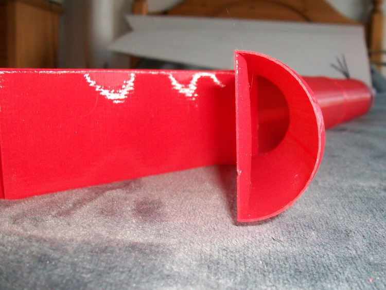
So I printed a pair of simple 1/2 bell inlets to emulate the sort of thing the Gnat would have.
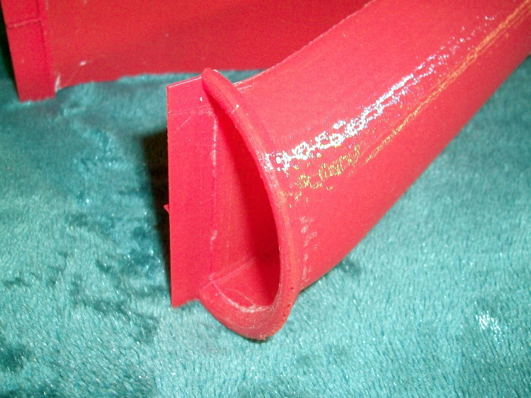
With these in place the EDF generated 16.2 oz thrust, drawing 22.2 A using 212 W.
The complete inlet weighs 39 g.
It would likely be lighter in Depron but the inside of the printed duct is very smooth and the bends have proper radii.
Pleasantly pleased with this result given the extreme diameter to length ratio of the inlet.
The EDF on its own but without a bell mouth just managed 16 oz thrust.
When fitted to the full duct it very nearly collapsed the flat side of the inlet ducts!
So I printed a pair of simple 1/2 bell inlets to emulate the sort of thing the Gnat would have.
With these in place the EDF generated 16.2 oz thrust, drawing 22.2 A using 212 W.
The complete inlet weighs 39 g.
It would likely be lighter in Depron but the inside of the printed duct is very smooth and the bends have proper radii.
Pleasantly pleased with this result given the extreme diameter to length ratio of the inlet.
Thanks: Phil Wood, Eric, Klipkopwildlife, crash happy
Please Log in or Create an account to join the conversation.
- crash happy
-

- Offline
- Platinum Member
-

- Oops. did I say that out loud!
Less
More
- Posts: 1250
- Thank you received: 1203
06 Jan 2020 09:43 #5
by crash happy
Replied by crash happy on topic Folland Gnat T1
Fascinating stuff ! I presume the bell mouth will help increase the air flow ?
Please Log in or Create an account to join the conversation.
- Quorneng
-
Topic Author
- Offline
- Forum Master
-
Less
More
- Posts: 10058
- Thank you received: 19043
07 Jan 2020 01:04 - 07 Jan 2020 01:20 #6
by Quorneng
Replied by Quorneng on topic Folland Gnat T1
The Bell mouth function was actually two fold, airflow and structural.
The flat side of the inlet was rather floppy so the airflow started to pull in it which restricted the airflow so it sucked harder and pulled it in even more. Approaching full power it reduced the inlet area by nearly 50% so I stopped the test run rather quickly before the whole duct collapsed.
I have been playing with the drawings working out the size so the duct area exactly matches the scale inlets.
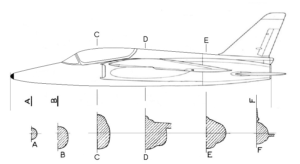
It will have a span of 810 mm
It was only when I started looking at the detail I realised just how different the 2 seat trainer (as used by the Red Arrows) was from the single seat Gnat F1 (as used by the Indian air force). For instance the F1 had no ailerons but used the all moving tail planes as 'elevons' which then allowed full span flaps!
So the T1 Gnat had a completely different tail plane (fixed with elevators), different wing (with flaps and ailerons), a much bigger fin, a longer revised fuselage to accommodate two seats with much less internal fuel hence the permanent under wing tanks otherwise it was the same!
The flat side of the inlet was rather floppy so the airflow started to pull in it which restricted the airflow so it sucked harder and pulled it in even more. Approaching full power it reduced the inlet area by nearly 50% so I stopped the test run rather quickly before the whole duct collapsed.
I have been playing with the drawings working out the size so the duct area exactly matches the scale inlets.
It will have a span of 810 mm
It was only when I started looking at the detail I realised just how different the 2 seat trainer (as used by the Red Arrows) was from the single seat Gnat F1 (as used by the Indian air force). For instance the F1 had no ailerons but used the all moving tail planes as 'elevons' which then allowed full span flaps!
So the T1 Gnat had a completely different tail plane (fixed with elevators), different wing (with flaps and ailerons), a much bigger fin, a longer revised fuselage to accommodate two seats with much less internal fuel hence the permanent under wing tanks otherwise it was the same!
Last edit: 07 Jan 2020 01:20 by Quorneng.
Thanks: Phil Wood, Klipkopwildlife, Flytilbroke, crash happy
Please Log in or Create an account to join the conversation.
- Quorneng
-
Topic Author
- Offline
- Forum Master
-
Less
More
- Posts: 10058
- Thank you received: 19043
07 Jan 2020 21:36 #7
by Quorneng
Replied by Quorneng on topic Folland Gnat T1
A bit more 'tidying up' of the side view and then printed out to the required size with the EDF and duct resting on top.

I had to confirm that the duct 'as printed' would fit both for length, the inlet positions and the exhaust diameter.
Looks good so far.
I had to confirm that the duct 'as printed' would fit both for length, the inlet positions and the exhaust diameter.
Looks good so far.
Thanks: Phil Wood, Klipkopwildlife, crash happy
Please Log in or Create an account to join the conversation.
- Quorneng
-
Topic Author
- Offline
- Forum Master
-
Less
More
- Posts: 10058
- Thank you received: 19043
08 Jan 2020 23:18 - 08 Jan 2020 23:24 #8
by Quorneng
Replied by Quorneng on topic Folland Gnat T1
The duct with the scale inlets on the 40 mm EDF using a 'big' 3s delivers 16.2 oz thrust drawing 22.2 A and 212 W.
Interestingly the EDF alone but without a bell mouth only generates 15 oz and I did it twice as I did not believe it!
Spent most of the rest of the day preparing the plans, actually it involves redrawing the fuzzy lines one at a time on the 3 view. A somewhat tedious process but once done you soon forget how long it takes.
With just one pixel wide lines it can be tile printed to the required size.

The above printed duct is really just a prototype to check it could be done and to test its performance.
A revised 'flight worthy' and slightly lighter one is under way.
Interestingly the EDF alone but without a bell mouth only generates 15 oz and I did it twice as I did not believe it!
Spent most of the rest of the day preparing the plans, actually it involves redrawing the fuzzy lines one at a time on the 3 view. A somewhat tedious process but once done you soon forget how long it takes.
With just one pixel wide lines it can be tile printed to the required size.
The above printed duct is really just a prototype to check it could be done and to test its performance.
A revised 'flight worthy' and slightly lighter one is under way.
Last edit: 08 Jan 2020 23:24 by Quorneng.
Thanks: Phil Wood, Eric, Klipkopwildlife, Flytilbroke, Ralpharr2001, crash happy
Please Log in or Create an account to join the conversation.
- Quorneng
-
Topic Author
- Offline
- Forum Master
-
Less
More
- Posts: 10058
- Thank you received: 19043
09 Jan 2020 20:54 #9
by Quorneng
Replied by Quorneng on topic Folland Gnat T1
The inlet section of the 'flight' duct.

The short Depron sections make up the change from a semicircular cross section to the Gnat scale shape inlet. it had a 2.5 mm radius bell mouth on 3 sides.
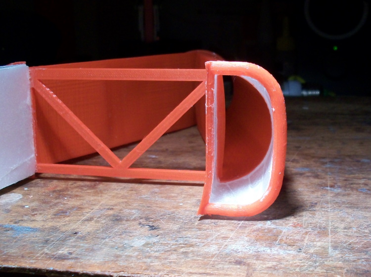
To save weight the printed wall thickness is reduced to 0.25 mm from 0.3 mm on the prototype duct. This is in part to compensate for the fact the 'flight' duct will be 120 mm longer.
With 16 oz thrust available the next question will be weight.
EDF and duct 3.4 oz
1500 mAh 3s 3.5 oz
ESC, 4 servos and rx 2.1 oz
My 'all up' target weight is to match the thrust.
The short Depron sections make up the change from a semicircular cross section to the Gnat scale shape inlet. it had a 2.5 mm radius bell mouth on 3 sides.
To save weight the printed wall thickness is reduced to 0.25 mm from 0.3 mm on the prototype duct. This is in part to compensate for the fact the 'flight' duct will be 120 mm longer.
With 16 oz thrust available the next question will be weight.
EDF and duct 3.4 oz
1500 mAh 3s 3.5 oz
ESC, 4 servos and rx 2.1 oz
My 'all up' target weight is to match the thrust.
Thanks: Phil Wood, Eric, Klipkopwildlife, THE BLACKBIRD, crash happy
Please Log in or Create an account to join the conversation.
- Eric
-

- Offline
- Moderator
-

Less
More
- Posts: 15406
- Thank you received: 14306
09 Jan 2020 23:13 #10
by Eric
if you are calm and collected when all about you are going berserk - you've missed something important!
Replied by Eric on topic Folland Gnat T1
If you get close to 1-1, you will have more thrust than the real one! 
if you are calm and collected when all about you are going berserk - you've missed something important!
Please Log in or Create an account to join the conversation.
- Quorneng
-
Topic Author
- Offline
- Forum Master
-
Less
More
- Posts: 10058
- Thank you received: 19043
10 Jan 2020 19:42 #11
by Quorneng
Replied by Quorneng on topic Folland Gnat T1
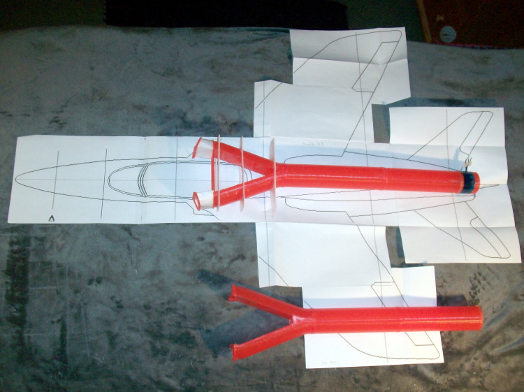
The complete 'flight' duct sitting on the plan with the prototype for comparison.
The first 3 formers in 2 mm Depron.
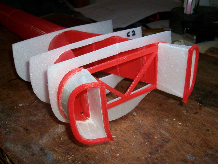
They are flat topped as the wing just clears the duct.
The plan only has 6 cross sections shown but it will need 17 formers in total so some 'interpretation' will be required for create the intermediates ones.
A big advantage of using Depron is the former can be easily sanded, or even added to, to give a smooth transition between them.
The first 3 formers in 2 mm Depron.
They are flat topped as the wing just clears the duct.
The plan only has 6 cross sections shown but it will need 17 formers in total so some 'interpretation' will be required for create the intermediates ones.
A big advantage of using Depron is the former can be easily sanded, or even added to, to give a smooth transition between them.
Thanks: Phil Wood, Klipkopwildlife, Ralpharr2001, crash happy
Please Log in or Create an account to join the conversation.
- Quorneng
-
Topic Author
- Offline
- Forum Master
-
Less
More
- Posts: 10058
- Thank you received: 19043
12 Jan 2020 13:33 #12
by Quorneng
Replied by Quorneng on topic Folland Gnat T1
An unusual picture of the duct with its formers.
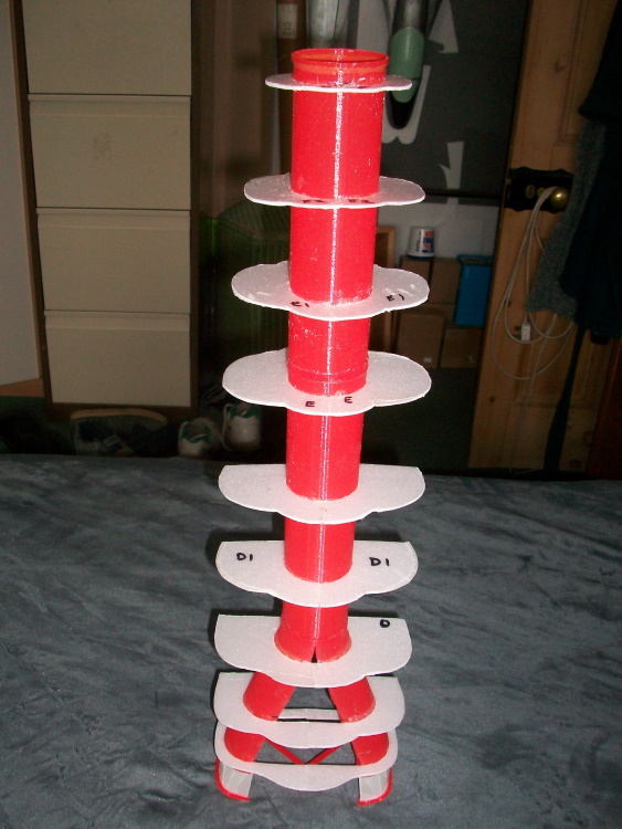
With the EDF on the end this whole part of the fuselage can be planked in one go, however the cockpit/nose section will have to be built separately using the 'half section over the plan' method and then glued on.
With the EDF on the end this whole part of the fuselage can be planked in one go, however the cockpit/nose section will have to be built separately using the 'half section over the plan' method and then glued on.
Thanks: Phil Wood, Klipkopwildlife, Ralpharr2001, crash happy
Please Log in or Create an account to join the conversation.
- Quorneng
-
Topic Author
- Offline
- Forum Master
-
Less
More
- Posts: 10058
- Thank you received: 19043
14 Jan 2020 19:04 - 14 Jan 2020 19:05 #13
by Quorneng
Replied by Quorneng on topic Folland Gnat T1
One result of having the EDF right at the back is the battery has to go along way forward to compensate which means seriously long motor wires.
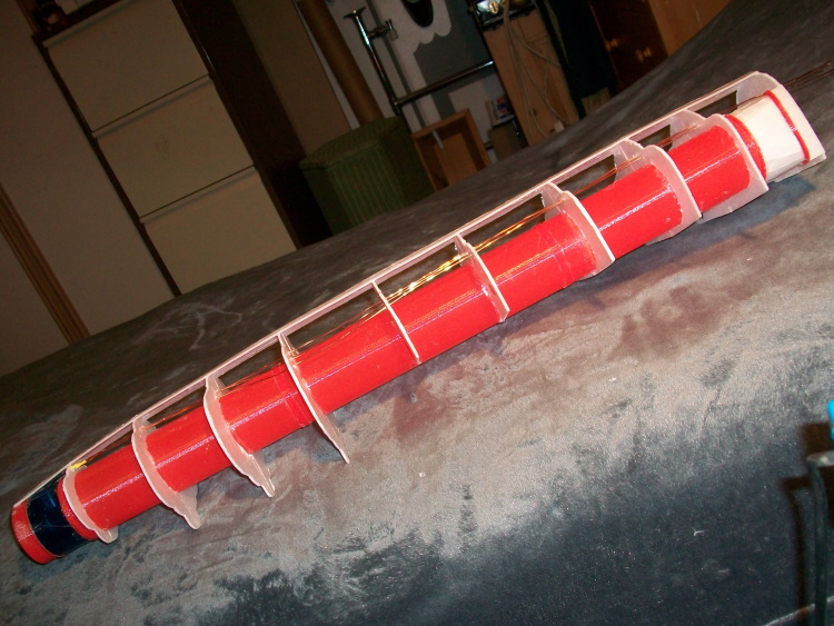
Lacquered magnet wire as I have done with some of my other EDFs. It saves the weight of the silicon insulation.
The ESC will be mounted flush with the fuselage skin just ahead of the left air intake so it will at least have a positive airflow over it.
The stab? rx will be mounted on the cockpit floor so hopefully reception will not be too badly 'masked' by the long motor wires.
Lacquered magnet wire as I have done with some of my other EDFs. It saves the weight of the silicon insulation.
The ESC will be mounted flush with the fuselage skin just ahead of the left air intake so it will at least have a positive airflow over it.
The stab? rx will be mounted on the cockpit floor so hopefully reception will not be too badly 'masked' by the long motor wires.
Last edit: 14 Jan 2020 19:05 by Quorneng.
Thanks: Phil Wood, Klipkopwildlife, THE BLACKBIRD, crash happy
Please Log in or Create an account to join the conversation.
- Eric
-
- Offline
- Moderator
-
Less
More
- Posts: 15406
- Thank you received: 14306
15 Jan 2020 10:37 #14
by Eric
if you are calm and collected when all about you are going berserk - you've missed something important!
Replied by Eric on topic Folland Gnat T1
Mount your antennas at 90' to the motor wires, then they won't be masked - (one up and down, one left and right).
if you are calm and collected when all about you are going berserk - you've missed something important!
Please Log in or Create an account to join the conversation.
- paul d
-
- Offline
- Forum Veteran
-

Less
More
- Posts: 2074
- Thank you received: 2292
15 Jan 2020 13:24 #15
by paul d
balsa is best.
Replied by paul d on topic Folland Gnat T1
Surely some form of 'screened wire' is the way to go?
balsa is best.
Please Log in or Create an account to join the conversation.
Time to create page: 0.669 seconds