
- Posts: 9436
- Thank you received: 19043
DH 91 Albatross
- Quorneng
-
 Topic Author
- Offline
- Forum Master
-

Less
More
18 Apr 2018 15:31 #16
by Quorneng
Replied by Quorneng on topic DH 91 Albatross
Yes I am printing for speed not surface finish. There does not seem much point for a super finish with a Depron finish to the rest of the plane. 
As Tony says PLA is plenty hard enough to be sanded but with light weight structures only 0.3 mm thick there is not much 'meat' to go at!
The Mk4 version of the Albatross nacelle to the more or less the correct profile
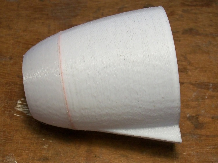
Holes are included in the bulkhead

A scale exit duct provides some motor cooling.

It is printed in two parts and glued together as this gives a better surface to mount the motor on.
The nacelle weighs 7.5 g. The motor less prop weighs 25 g.
May have to get "creative" for the 30 mm spinner
As Tony says PLA is plenty hard enough to be sanded but with light weight structures only 0.3 mm thick there is not much 'meat' to go at!
The Mk4 version of the Albatross nacelle to the more or less the correct profile
Holes are included in the bulkhead
A scale exit duct provides some motor cooling.
It is printed in two parts and glued together as this gives a better surface to mount the motor on.
The nacelle weighs 7.5 g. The motor less prop weighs 25 g.
May have to get "creative" for the 30 mm spinner
Thanks: Klipkopwildlife
Please Log in or Create an account to join the conversation.
- Ex-Member
- User
-

Less
More
- Thank you received: 0
18 Apr 2018 18:08 #17
by Ex-Member
Replied by Ex-Member on topic DH 91 Albatross
Thanks for the responses.
I realise that you're printing for speed and lightness Q, so your requirements are different to mine. What I'd really like to know is: Is it possible to either sand or turn the printed piece in a lathe or similar to get a smooth finish?
I realise that you're printing for speed and lightness Q, so your requirements are different to mine. What I'd really like to know is: Is it possible to either sand or turn the printed piece in a lathe or similar to get a smooth finish?
Please Log in or Create an account to join the conversation.
- Ex-Member
- User
-
Less
More
- Thank you received: 0
18 Apr 2018 18:11 #18
by Ex-Member
Replied by Ex-Member on topic DH 91 Albatross
wet and dry works well Andy.
Tony B
Tony B
Please Log in or Create an account to join the conversation.
- Quorneng
-
Topic Author
- Offline
- Forum Master
-
Less
More
- Posts: 9436
- Thank you received: 19043
19 Apr 2018 00:28 - 19 Apr 2018 00:30 #19
by Quorneng
Replied by Quorneng on topic DH 91 Albatross
Andy
It is not possible to get a gloss finish off the printer but if you select a very fine layer height (0.05 mm) it can give a surface equivalent to a 'turned' finish but at 20 layers to the 1 mm anything big will take a long time!
For thin wall lightweight structures the problem is the underlying structure tends to show through on the surface but this problem largely disappears if the outer wall is specified 2 or 3 layers thick which then also leaves adequate material to sand down.
The scale nacelle with the motor and a 6x3 prop.
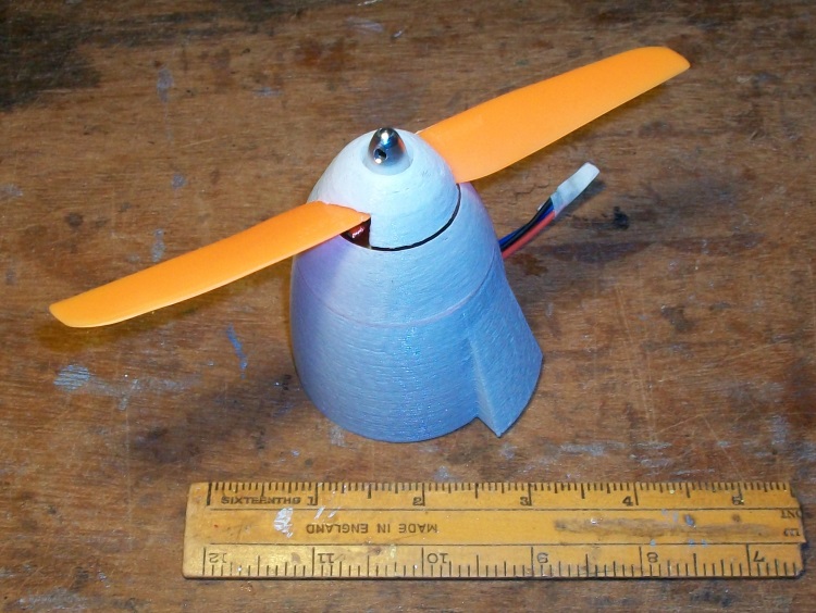
The "spinner" is a reasonable representation of the full size and is retained by the supplied nut. It has to be done this way as two of the motors have LH threads!
It is not possible to get a gloss finish off the printer but if you select a very fine layer height (0.05 mm) it can give a surface equivalent to a 'turned' finish but at 20 layers to the 1 mm anything big will take a long time!
For thin wall lightweight structures the problem is the underlying structure tends to show through on the surface but this problem largely disappears if the outer wall is specified 2 or 3 layers thick which then also leaves adequate material to sand down.
The scale nacelle with the motor and a 6x3 prop.
The "spinner" is a reasonable representation of the full size and is retained by the supplied nut. It has to be done this way as two of the motors have LH threads!
Last edit: 19 Apr 2018 00:30 by Quorneng.
Thanks: Klipkopwildlife, boz
Please Log in or Create an account to join the conversation.
- Quorneng
-
Topic Author
- Offline
- Forum Master
-
Less
More
- Posts: 9436
- Thank you received: 19043
20 Apr 2018 20:15 #20
by Quorneng
Replied by Quorneng on topic DH 91 Albatross
More out of curiosity than for any specific need I printed a 10 mm 'test cube' using a 0.05 mm layer height to see what the surface would look like.
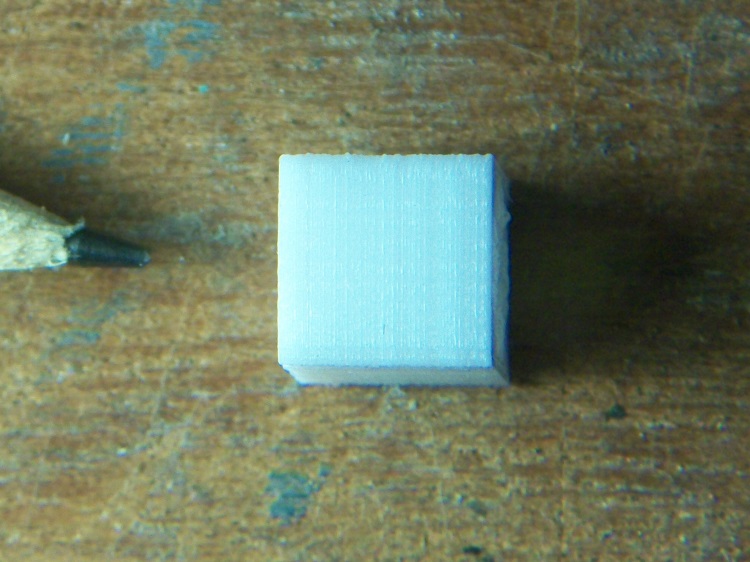
Not easy to photograph as I had to take the picture through a big lens to stand any chance of showing the surface detail.
The point of the pencil is 1 mm across.
Not easy to photograph as I had to take the picture through a big lens to stand any chance of showing the surface detail.
The point of the pencil is 1 mm across.
Thanks: Klipkopwildlife, Ex-Member, boz
Please Log in or Create an account to join the conversation.
- Quorneng
-
Topic Author
- Offline
- Forum Master
-
Less
More
- Posts: 9436
- Thank you received: 19043
21 Apr 2018 16:16 #21
by Quorneng
Replied by Quorneng on topic DH 91 Albatross
Spent much of today printing out the other 3 nacelles and spinners.
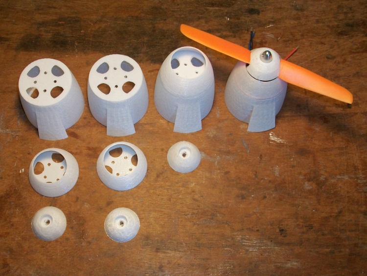
These show the 'submerged' printing used to create the front and rear parts of the nacelle from the same STL file.


It could be printed as one piece but the motor mount bulkhead would require 'support' printing to be included as well. The 'support' is fairly easily removed but it leaves a rather uneven surface, not ideal for a motor mount.
I have also test run the completed nacelle. It pulls just over 100W on a 3s at a screaming 18k revs. Hand held so no direct thrust measurement but certainly 'adequate'. Indeed with a total of 400W in what will hopefully be a sub 2 lb plane should give it unlimited vertical! :woohoo:
These show the 'submerged' printing used to create the front and rear parts of the nacelle from the same STL file.
It could be printed as one piece but the motor mount bulkhead would require 'support' printing to be included as well. The 'support' is fairly easily removed but it leaves a rather uneven surface, not ideal for a motor mount.
I have also test run the completed nacelle. It pulls just over 100W on a 3s at a screaming 18k revs. Hand held so no direct thrust measurement but certainly 'adequate'. Indeed with a total of 400W in what will hopefully be a sub 2 lb plane should give it unlimited vertical! :woohoo:
Thanks: Klipkopwildlife, THE BLACKBIRD, Ex-Member, one tenor, boz
Please Log in or Create an account to join the conversation.
- Quorneng
-
Topic Author
- Offline
- Forum Master
-
Less
More
- Posts: 9436
- Thank you received: 19043
23 Apr 2018 19:52 #22
by Quorneng
Replied by Quorneng on topic DH 91 Albatross
The wing plan printed out to the required size.

And to my relief the printed engine nacelle is just about the right size.
According to the Incomplete Guide to Aerofoil Usage the Albatross used an RAF 34 'mod' wing section root to tip. No idea of what the 'mod' actually was but this is the standard RAF 34 section.
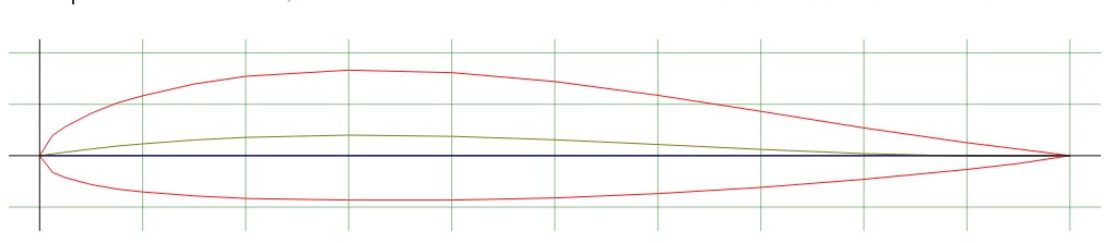
Nothing unusual except for the slight reverse camber towards the trailing edge.
It has a 12.6% t/c ratio. OK for the inner section carrying the engines but it may pay to thin it out a bit towards the tip.
And to my relief the printed engine nacelle is just about the right size.
According to the Incomplete Guide to Aerofoil Usage the Albatross used an RAF 34 'mod' wing section root to tip. No idea of what the 'mod' actually was but this is the standard RAF 34 section.
Nothing unusual except for the slight reverse camber towards the trailing edge.
It has a 12.6% t/c ratio. OK for the inner section carrying the engines but it may pay to thin it out a bit towards the tip.
Thanks: Klipkopwildlife, Ex-Member, boz, Squirrelnet
Please Log in or Create an account to join the conversation.
- one tenor
-

- Offline
- Forum Veteran
-

- johnpcalex@gmail.com
23 Apr 2018 21:55 #23
by one tenor
Anything will fly given enough power
Replied by one tenor on topic DH 91 Albatross
Good idea. Maybe that was the "MOD" with perhaps a bit more reflex as well for those tapered wings ? [badass]
Anything will fly given enough power
Please Log in or Create an account to join the conversation.
- Quorneng
-
Topic Author
- Offline
- Forum Master
-
Less
More
- Posts: 9436
- Thank you received: 19043
25 Apr 2018 16:44 #24
by Quorneng
Replied by Quorneng on topic DH 91 Albatross
I intend to use a similar wing construction to that I used on the A350. Printed ribs with a 2 mm Depron skin that incorporates balsa spar flanges.
The next tricky bit is organising the retracts. As a relatively small plane the wing is quite thin and the retracts are pretty close to the leading edge so it is quite a struggle to get them in.
A test installation of the retract unit held between two appropriately sized RAF 34 section ribs.
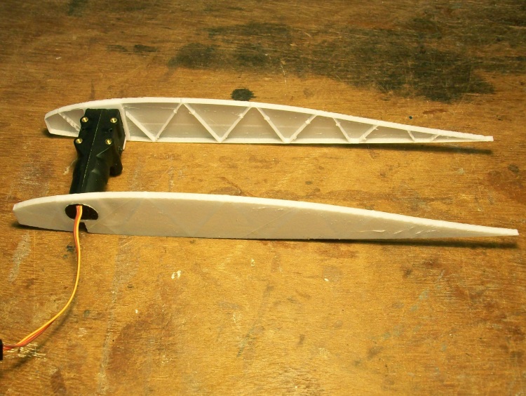

By using the retract unit itself as a structural member the landing loads are spread into a significant part of the Depron
wing structure with virtually no weight penalty.
The next tricky bit is organising the retracts. As a relatively small plane the wing is quite thin and the retracts are pretty close to the leading edge so it is quite a struggle to get them in.
A test installation of the retract unit held between two appropriately sized RAF 34 section ribs.
By using the retract unit itself as a structural member the landing loads are spread into a significant part of the Depron
wing structure with virtually no weight penalty.
Thanks: Klipkopwildlife, THE BLACKBIRD, Ex-Member, Ralpharr2001, boz, Mike Rolls, Squirrelnet
Please Log in or Create an account to join the conversation.
- Quorneng
-
Topic Author
- Offline
- Forum Master
-
Less
More
- Posts: 9436
- Thank you received: 19043
26 Apr 2018 20:31 #25
by Quorneng
Replied by Quorneng on topic DH 91 Albatross
I've been 3D printing wing ribs. There will be 16 each side. Of course all a different size but with the same RAF 34 section although they are 'thinned' a bit towards the tip. All done from a 'master' rib and using the 'scaling' feature in CURA.
The root and tip ribs.
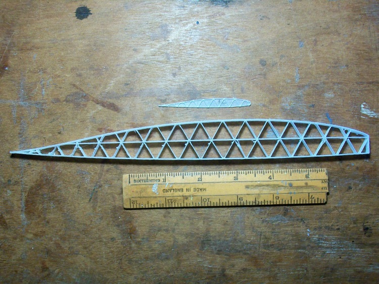
Another wing with considerable taper!
Only the top surface of the root rib is RAF 34 as its underside has to match the fuselage profile.
The root and tip ribs.
Another wing with considerable taper!
Only the top surface of the root rib is RAF 34 as its underside has to match the fuselage profile.
Thanks: Klipkopwildlife, Ex-Member, boz, Mike Rolls
Please Log in or Create an account to join the conversation.
- Mike Rolls
-

- Offline
- Elite Member
-

Less
More
- Posts: 634
- Thank you received: 573
27 Apr 2018 05:25 #26
by Mike Rolls
The older I get, the better I was!
Replied by Mike Rolls on topic DH 91 Albatross
That is some taper. Will you be using any washout?
Mike
Mike
The older I get, the better I was!
Please Log in or Create an account to join the conversation.
- Quorneng
-
Topic Author
- Offline
- Forum Master
-
Less
More
- Posts: 9436
- Thank you received: 19043
27 Apr 2018 12:21 #27
by Quorneng
Replied by Quorneng on topic DH 91 Albatross
mike
To be perfectly honest I have not really decided how I will even make the wing. :woohoo:
One disadvantage of a stressed skin wing structure is it has virtually no stiffness until a substantial portion of the skin is in place. Not too difficult with something like a Clark Y section that has a substantial area of flat bottom to build up from but the RAF 34 hasn't a flat surface anywhere!
It may be possible to actually use this lack of stiffness to get the wing build underway and only set up the wing accurately when the all the ribs and full underside skin are in place only 'locking' the structure when the top front portion of the skin goes on so making a torsion "D" box with the spar.
Still thinking but in the meantime I have created a lighter version of the big centre rib.

Unlike the other wing ribs in this case the 'web' is in the middle of the 6 mm thick rib. At 3.4 g it is 25% lighter and just as stiff and strong as the 'open' structure version.
To be perfectly honest I have not really decided how I will even make the wing. :woohoo:
One disadvantage of a stressed skin wing structure is it has virtually no stiffness until a substantial portion of the skin is in place. Not too difficult with something like a Clark Y section that has a substantial area of flat bottom to build up from but the RAF 34 hasn't a flat surface anywhere!
It may be possible to actually use this lack of stiffness to get the wing build underway and only set up the wing accurately when the all the ribs and full underside skin are in place only 'locking' the structure when the top front portion of the skin goes on so making a torsion "D" box with the spar.
Still thinking but in the meantime I have created a lighter version of the big centre rib.
Unlike the other wing ribs in this case the 'web' is in the middle of the 6 mm thick rib. At 3.4 g it is 25% lighter and just as stiff and strong as the 'open' structure version.
Thanks: Ex-Member, boz, Mike Rolls
Please Log in or Create an account to join the conversation.
- Quorneng
-
Topic Author
- Offline
- Forum Master
-
Less
More
- Posts: 9436
- Thank you received: 19043
04 May 2018 10:49 - 04 May 2018 10:50 #28
by Quorneng
Replied by Quorneng on topic DH 91 Albatross
With the chicken run complete (but 50% bigger than originally planned!) and the arrival of a retract unit (slow boat from China) I can complete the 'set' of five 3D printed ribs that make up the wing centre section.
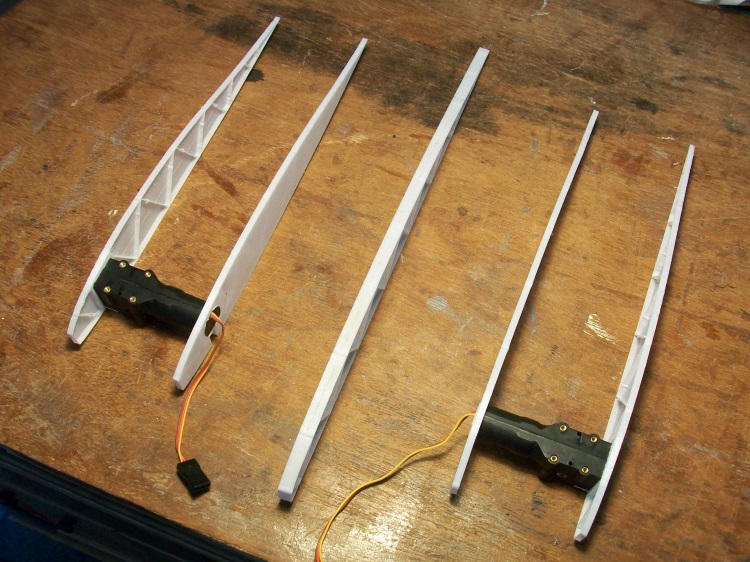
And in this box are the rest of the ribs all 24 of them!
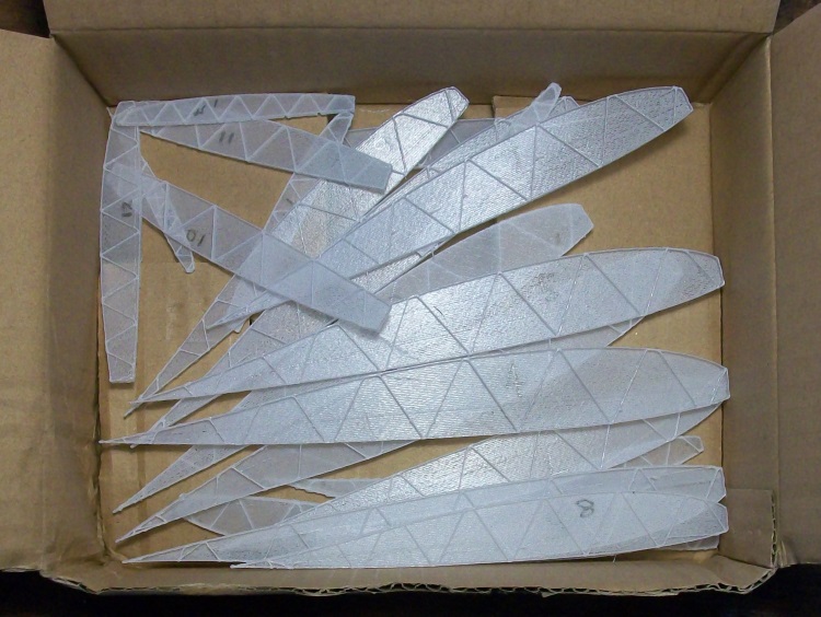
Printed in L & R pairs and scaled from a master, actually rib no 4 as ribs 1 to 3 are "specials". Even the scaling is not uniform as the ribs get proportionally a bit thinner towards the tip. They have to as the wing skin thickness is a constant 2 mm so makes the wing section proportionally thicker.
I have bought the 2 mm Depron sheet so it looks like I shall have to knuckle down and actually start to make the wing.
And in this box are the rest of the ribs all 24 of them!
Printed in L & R pairs and scaled from a master, actually rib no 4 as ribs 1 to 3 are "specials". Even the scaling is not uniform as the ribs get proportionally a bit thinner towards the tip. They have to as the wing skin thickness is a constant 2 mm so makes the wing section proportionally thicker.
I have bought the 2 mm Depron sheet so it looks like I shall have to knuckle down and actually start to make the wing.
Last edit: 04 May 2018 10:50 by Quorneng.
Thanks: Klipkopwildlife, Ex-Member, boz, Mike Rolls, Squirrelnet
Please Log in or Create an account to join the conversation.
- Quorneng
-
Topic Author
- Offline
- Forum Master
-
Less
More
- Posts: 9436
- Thank you received: 19043
08 May 2018 17:51 - 08 May 2018 17:52 #29
by Quorneng
Replied by Quorneng on topic DH 91 Albatross
Not much progress what with my PC being completely rebuilt with new motherboard and memory as well as having to tow my wife's car back - no clutch!
The 2 mm Deporn lower wing skin with its integral 2mm balsa spar flange.
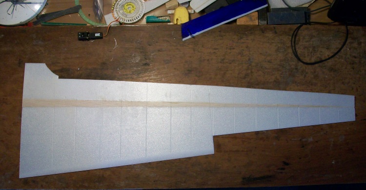
The skin will be 'formed' to more or less follow the ribs under side shape. They will then be progressively glued in place 'free hand' making full use of UHU POR's excellent 'contact adhesive' properties.
Next will be the Depron shear webs between the ribs and then the 6 mm Depron leading edge. The wing will still have very little torsional rigidity so it will only need 'blocking up' accurately when the top leading edge wing skin and spar top flange go on so creating a rigid "D" box structure.
Well that's the plan!
The 2 mm Deporn lower wing skin with its integral 2mm balsa spar flange.
The skin will be 'formed' to more or less follow the ribs under side shape. They will then be progressively glued in place 'free hand' making full use of UHU POR's excellent 'contact adhesive' properties.
Next will be the Depron shear webs between the ribs and then the 6 mm Depron leading edge. The wing will still have very little torsional rigidity so it will only need 'blocking up' accurately when the top leading edge wing skin and spar top flange go on so creating a rigid "D" box structure.
Well that's the plan!
Last edit: 08 May 2018 17:52 by Quorneng.
Thanks: Klipkopwildlife, boz, Mike Rolls, Squirrelnet
Please Log in or Create an account to join the conversation.
- Eric
-

- Offline
- Moderator
-

Less
More
- Posts: 13726
- Thank you received: 14467
08 May 2018 20:52 #30
by Eric
if you are calm and collected when all about you are going berserk - you've missed something important!
Replied by Eric on topic DH 91 Albatross
no clutch!
The 2 mm Deporn lower wing skin -
Freudian slip there, Simon ? [badass]
The 2 mm Deporn lower wing skin -
Freudian slip there, Simon ? [badass]
if you are calm and collected when all about you are going berserk - you've missed something important!
Thanks: boz
Please Log in or Create an account to join the conversation.
Time to create page: 1.999 seconds