
- Posts: 9436
- Thank you received: 19043
DH 91 Albatross
- Quorneng
-
 Topic Author
- Offline
- Forum Master
-

Less
More
05 Jun 2018 00:32 - 05 Jun 2018 00:36 #46
by Quorneng
Replied by Quorneng on topic DH 91 Albatross
My preferred installation places the rudder and elevator servos within their respective flying surface as is done with ailerons. However with a dihedral tail plane and twin rudders it would mean four servos right at the back but it would keep 'slop' to a minimum. 
As the dihedral angle is small I may be able to 'fudge' a universal joint between the elevators so a single fuselage mounted servo can be used.
The neatest way to operate twin rudders is with pull/pull cables, in my case with 5 lb nylon mono filament line. Simplest is to run the line over the surface of the tail plane to a fuselage mounted servo.
Of course the lightest solution of all is to fix the rudders and fly bank and yank! :woohoo:
I think it will prudent to build a 'test' rudder and elevator installation so I have printed the formers for the rear section of the fuselage..

Which correspond to this, formers 12 to 17.
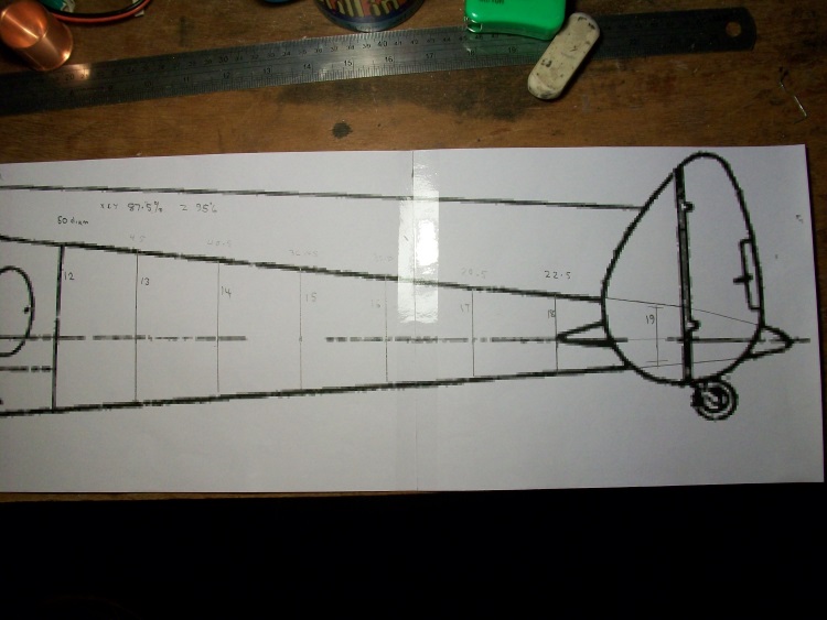
If it all works the 'test' assembly will simply be used in the final fuselage as it will have to be built in atleast 3 sections anyway.
As the dihedral angle is small I may be able to 'fudge' a universal joint between the elevators so a single fuselage mounted servo can be used.
The neatest way to operate twin rudders is with pull/pull cables, in my case with 5 lb nylon mono filament line.
Simplest is to run the line over the surface of the tail plane to a fuselage mounted servo.Of course the lightest solution of all is to fix the rudders and fly bank and yank! :woohoo:
I think it will prudent to build a 'test' rudder and elevator installation so I have printed the formers for the rear section of the fuselage..
Which correspond to this, formers 12 to 17.
If it all works the 'test' assembly will simply be used in the final fuselage as it will have to be built in atleast 3 sections anyway.
Last edit: 05 Jun 2018 00:36 by Quorneng.
Thanks: Klipkopwildlife, blue123, boz
Please Log in or Create an account to join the conversation.
- Quorneng
-
Topic Author
- Offline
- Forum Master
-
Less
More
- Posts: 9436
- Thank you received: 19043
12 Jun 2018 23:55 #47
by Quorneng
Replied by Quorneng on topic DH 91 Albatross
With the car in the garage again (log story) I could put some time in on the Albatross.
The U/C legs (1/8 stainless!) bent to shape and fixed into the retracts.
Wheel down.
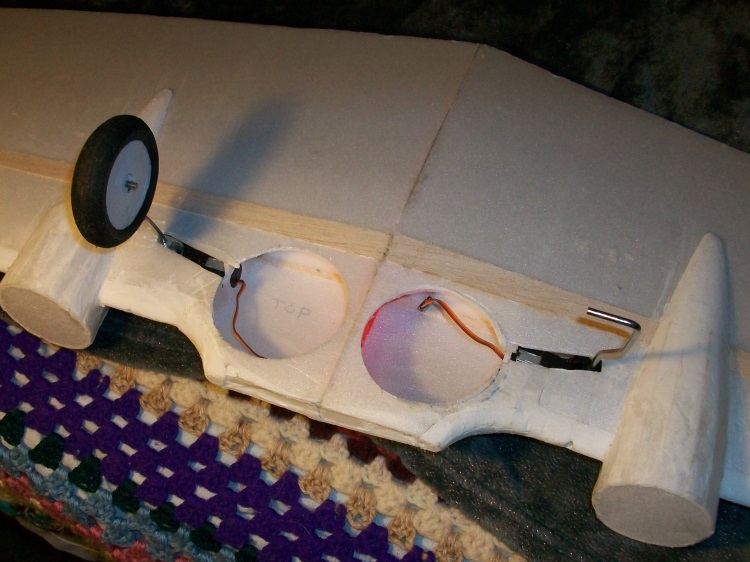
Wheel up.
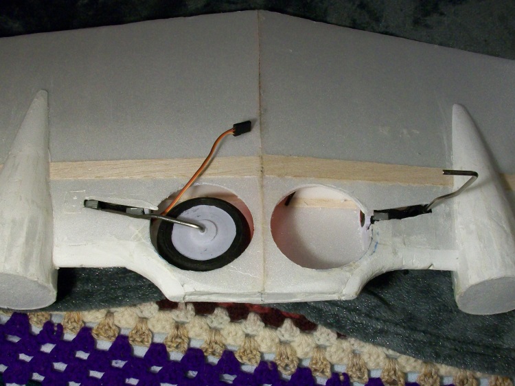
As the U/C legs have no 'give' what so ever it uses printed sprung wheels.

The outer panels are only glued to the centre part at the rim which allows the axle 3 mm of vertical movement.
The "tyre" part is made up of three 6 mm Depron rings sanded to shape using a pillar drill.
The complete 60 mm (2 3 /8 ") diam wheel weighs 5.1 g.
The U/C legs (1/8 stainless!) bent to shape and fixed into the retracts.
Wheel down.
Wheel up.
As the U/C legs have no 'give' what so ever it uses printed sprung wheels.
The outer panels are only glued to the centre part at the rim which allows the axle 3 mm of vertical movement.
The "tyre" part is made up of three 6 mm Depron rings sanded to shape using a pillar drill.
The complete 60 mm (2 3 /8 ") diam wheel weighs 5.1 g.
Thanks: Klipkopwildlife, Mowerman, boz, Mike Rolls, Squirrelnet
Please Log in or Create an account to join the conversation.
- Quorneng
-
Topic Author
- Offline
- Forum Master
-
Less
More
- Posts: 9436
- Thank you received: 19043
13 Jun 2018 21:29 #48
by Quorneng
Replied by Quorneng on topic DH 91 Albatross
After another couple of hours printing two important bits.
The support for the U/C door and the wheel retaining collar.
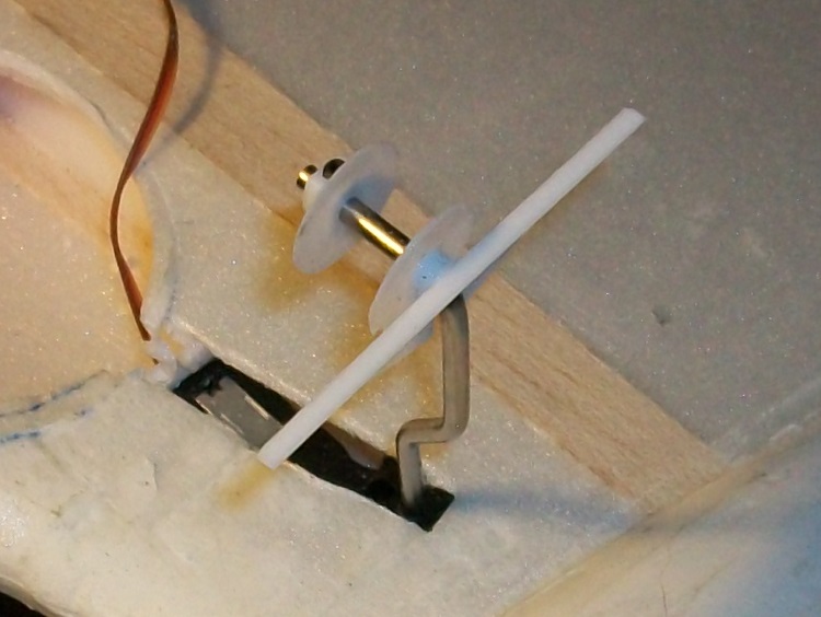
Then a couple more hours 'fiddling' to get it to actually work and the LH retract is complete and tested.
The support for the U/C door and the wheel retaining collar.
Then a couple more hours 'fiddling' to get it to actually work and the LH retract is complete and tested.
Thanks: Klipkopwildlife, boz, Mike Rolls, Squirrelnet
Please Log in or Create an account to join the conversation.
- Mike Rolls
-

- Offline
- Elite Member
-

Less
More
- Posts: 634
- Thank you received: 573
14 Jun 2018 05:32 #49
by Mike Rolls
The older I get, the better I was!
Replied by Mike Rolls on topic DH 91 Albatross
If the wheel is still rotating as it comes up, is there any danger of it tangling that lead?
Mike
Mike
The older I get, the better I was!
Please Log in or Create an account to join the conversation.
- Eric
-

- Offline
- Moderator
-

Less
More
- Posts: 13726
- Thank you received: 14467
14 Jun 2018 10:21 #50
by Eric
if you are calm and collected when all about you are going berserk - you've missed something important!
Replied by Eric on topic DH 91 Albatross
That was a 'lash-up for testing. I assume the servo lead will be taped to the inside top surface.
Anyway, as the wheel will have the rotating mass of practically nothing, would it matter?
Anyway, as the wheel will have the rotating mass of practically nothing, would it matter?
if you are calm and collected when all about you are going berserk - you've missed something important!
Please Log in or Create an account to join the conversation.
- Mike Rolls
-
- Offline
- Elite Member
-
Less
More
- Posts: 634
- Thank you received: 573
14 Jun 2018 11:37 #51
by Mike Rolls
The older I get, the better I was!
Replied by Mike Rolls on topic DH 91 Albatross
I don't know - but as a firm believer in 'if anything CAN go wrong, it WILL go wrong.....
Mike
Mike
The older I get, the better I was!
Please Log in or Create an account to join the conversation.
- Quorneng
-
Topic Author
- Offline
- Forum Master
-
Less
More
- Posts: 9436
- Thank you received: 19043
14 Jun 2018 13:27 #52
by Quorneng
Replied by Quorneng on topic DH 91 Albatross
Don't worry it is just a functional test.
I am delaying fixing the retract leads permanently until I have built the centre section of the fuselage so I know exactly where I need them to come through the wing top skin.
I am delaying fixing the retract leads permanently until I have built the centre section of the fuselage so I know exactly where I need them to come through the wing top skin.
Thanks: boz, Mike Rolls
Please Log in or Create an account to join the conversation.
- Quorneng
-
Topic Author
- Offline
- Forum Master
-
Less
More
- Posts: 9436
- Thank you received: 19043
14 Jun 2018 19:28 #53
by Quorneng
Replied by Quorneng on topic DH 91 Albatross
A test with both UC legs complete but still with unsecured retract leads. 
Next I will make a start on the tail plane and rear fuselage.
Just as soon as the ESCs arrive from China I want to mount the motors to complete the electrical installation in the wing.
Next I will make a start on the tail plane and rear fuselage.
Just as soon as the ESCs arrive from China I want to mount the motors to complete the electrical installation in the wing.
Thanks: Eric, Klipkopwildlife, boz
Please Log in or Create an account to join the conversation.
- Quorneng
-
Topic Author
- Offline
- Forum Master
-
Less
More
- Posts: 9436
- Thank you received: 19043
17 Jun 2018 19:38 #54
by Quorneng
Replied by Quorneng on topic DH 91 Albatross
The L&R tailplanes.

All Depron - 2 mm skins over two Depron shear webs with 3 printed elevator hinges.
I am slowly coming round to the idea of simply fitting a servo for each elevator as the tail plane is just about thick enough to hide them.
It would of course be equally simple to mount a rudder servo in each fin but I am very conscious of the weight of four of even the tiny 3.7 g types so far back. :ohmy:
Somewhere I do have a pair of even smaller 2.5 g servos or as electric motors usually don't 'stop' in flight I could go even simpler and fly bank and yank with fixed rudders.
However with 4 motors spaced out along the wing I suspect some 'rudder' might be useful to counter any thrust imbalance between them. )
Thanks: Eric, Klipkopwildlife, boz, Mike Rolls, Squirrelnet
Please Log in or Create an account to join the conversation.
- Eric
-
- Offline
- Moderator
-
Less
More
- Posts: 13726
- Thank you received: 14467
17 Jun 2018 19:45 #55
by Eric
if you are calm and collected when all about you are going berserk - you've missed something important!
Replied by Eric on topic DH 91 Albatross
To keep rear weight down, how about only having one working rudder, to use more as a trim control than a directional one?
if you are calm and collected when all about you are going berserk - you've missed something important!
Thanks: boz
Please Log in or Create an account to join the conversation.
- Quorneng
-
Topic Author
- Offline
- Forum Master
-
Less
More
- Posts: 9436
- Thank you received: 19043
17 Jun 2018 22:00 #56
by Quorneng
Replied by Quorneng on topic DH 91 Albatross
If I kept to the simple 'servo in the fin' installation I would then have a 2.5 g off set weight distribution!
Such an offset could be useful to counter motor torque except it will use two pairs of CW and CCW props!
Such an offset could be useful to counter motor torque except it will use two pairs of CW and CCW props!
Thanks: boz
Please Log in or Create an account to join the conversation.
- one tenor
-

- Offline
- Forum Veteran
-

- johnpcalex@gmail.com
18 Jun 2018 01:14 #57
by one tenor
Anything will fly given enough power
Replied by one tenor on topic DH 91 Albatross
"HI why not link them and just use 2 servos :woohoo:
Anything will fly given enough power
Please Log in or Create an account to join the conversation.
- Quorneng
-
Topic Author
- Offline
- Forum Master
-
Less
More
- Posts: 9436
- Thank you received: 19043
18 Jun 2018 11:25 - 18 Jun 2018 11:26 #58
by Quorneng
Replied by Quorneng on topic DH 91 Albatross
OT
The tail plane has dihedral so joining the elevator halves together so they could be driven by a single servo would require some sort of universal joint. Not easy to be both super light and slop free at such a small size.
The rudders could only be realistically linked by an external rod which would have to be half way up the fin to clear the 'up' elevator travel. It would thus not only be rather visible (and create drag!) but also very prone to accidental damage.
I suspect the 4 servo solution will give the neatest appearance and also be the easiest to install.
I may have to install all four motors in the wing to get an idea of how much they will counter the weight of the servos in the tail so the battery does not have to go too far forward in the nose.
Last edit: 18 Jun 2018 11:26 by Quorneng.
Thanks: boz
Please Log in or Create an account to join the conversation.
- Quorneng
-
Topic Author
- Offline
- Forum Master
-
Less
More
- Posts: 9436
- Thank you received: 19043
20 Jun 2018 00:00 #59
by Quorneng
Replied by Quorneng on topic DH 91 Albatross
With the servod (3.7 and 2.5 g) in place the RH tail plane and fin can be tested for "full and free movement" with a servo tester.
I am not entirely happy with the fin to tail plane joint. It really needs a small printed internal brace.
As each hinge is printed in two parts, 5 hinges = 10 parts plus 2 horns and servo arm covers so 14 printed parts in each half tail plane and fin.
When complete the Albatross will have over 100! :ohmy:
Thanks: boz, Mike Rolls, Squirrelnet
Please Log in or Create an account to join the conversation.
- Quorneng
-
Topic Author
- Offline
- Forum Master
-
Less
More
- Posts: 9436
- Thank you received: 19043
21 Jun 2018 13:31 #60
by Quorneng
Replied by Quorneng on topic DH 91 Albatross
Built up the LH tail plane and rudder (I cut and printed all the parts when I did the RH side)
To feed the rudder servo wire down the tail plane the pins have to be extracted from the plug. Having achieved this I glued the fin in place with its internal printed brace and left it to set. Big mistake! Sods law came into play. :woohoo: I should have tested the servo first.
Had to get fairly brutal with the knife to separate the fin from the tail plane and then a bit more to extract the servo from the fin.
Fortunately POR remains pretty pliable even after 24 hours so the 'repair' does not look too bad with the replacement servo in the fin, and tested, before its wire is fed through the tail plane.

When it will be tested again!
To feed the rudder servo wire down the tail plane the pins have to be extracted from the plug. Having achieved this I glued the fin in place with its internal printed brace and left it to set. Big mistake! Sods law came into play. :woohoo: I should have tested the servo first.
Had to get fairly brutal with the knife to separate the fin from the tail plane and then a bit more to extract the servo from the fin.
Fortunately POR remains pretty pliable even after 24 hours so the 'repair' does not look too bad with the replacement servo in the fin, and tested
, before its wire is fed through the tail plane.
When it will be tested again!
Thanks: Klipkopwildlife, Mike Rolls, Squirrelnet
Please Log in or Create an account to join the conversation.
Time to create page: 1.116 seconds