
- Posts: 9436
- Thank you received: 19043
Depron Heinkel HE162
- Quorneng
-
 Topic Author
- Offline
- Forum Master
-

Less
More
07 Apr 2021 15:02 - 07 Apr 2021 15:03 #181
by Quorneng
Replied by Quorneng on topic Depron Heinkel HE162
The Ebay 2 mm Depron just delivered is the 'original' stuff that is surprisingly rigid and stiff. It was his last available so I guess he had bought a full box or two when it was available, cut it into postage size sheets and sold it on at a considerable mark up.
Anyway I thought it would be interesting to see just how heavy it was compared to the foam sheet that is available. The cheapest and most readily available are the green and grey 5 mm sheets used as a laminate underlay.
I do have some 3 mm Depron 'aero' sheet.
So using my 2 decimal place digital scales on selected test pieces to give density in g/sq m.
Green 5 mm 152.6
Grey 5 mm 130.0
Depron 2mm 111.8 The latest small size sheet.
Depron 2 mm 108.6 The Depron used to make the the He 162.
Depron 3 mm Aero 96.0
These result suggest the Depron part of the existing He 162 construction is just about as light as can be.
As the weather looks like any testing of the HE 162 is out of the question in the short term the first step will be to move the fan to the front of the existing duct to check if it works better and possibly allow the use of a 5s (or even 6s) battery. Perhaps more to the point it will need the minimum of more Depron to achieve it!
If that proves to work then it might be worth rebuilding the complete duct in 3 mm aero Depron but without any printed parts to save a bit of weight.
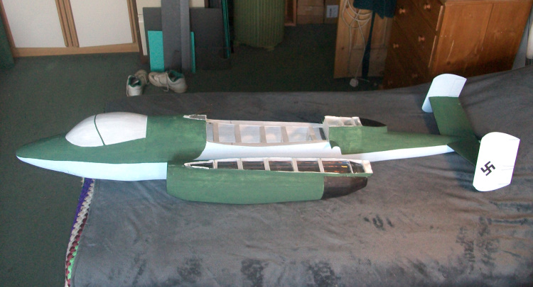
First job cut off the duct! :woohoo:
Anyway I thought it would be interesting to see just how heavy it was compared to the foam sheet that is available. The cheapest and most readily available are the green and grey 5 mm sheets used as a laminate underlay.
I do have some 3 mm Depron 'aero' sheet.
So using my 2 decimal place digital scales on selected test pieces to give density in g/sq m.
Green 5 mm 152.6
Grey 5 mm 130.0
Depron 2mm 111.8 The latest small size sheet.
Depron 2 mm 108.6 The Depron used to make the the He 162.
Depron 3 mm Aero 96.0
These result suggest the Depron part of the existing He 162 construction is just about as light as can be.
As the weather looks like any testing of the HE 162 is out of the question in the short term the first step will be to move the fan to the front of the existing duct to check if it works better and possibly allow the use of a 5s (or even 6s) battery. Perhaps more to the point it will need the minimum of more Depron to achieve it!
If that proves to work then it might be worth rebuilding the complete duct in 3 mm aero Depron but without any printed parts to save a bit of weight.
First job cut off the duct! :woohoo:
Last edit: 07 Apr 2021 15:03 by Quorneng.
Thanks: Klipkopwildlife, Ralpharr2001, crash happy
Please Log in or Create an account to join the conversation.
- paul d
-
- Offline
- Forum Veteran
-

Less
More
- Posts: 2074
- Thank you received: 2292
07 Apr 2021 18:47 #182
by paul d
balsa is best.
Replied by paul d on topic Depron Heinkel HE162
Interesting stuff, how do those weights compare to a sqm of 1/8th balsa? I don't have any super accurate scales, really should buy some..
balsa is best.
Thanks: Klipkopwildlife
Please Log in or Create an account to join the conversation.
- Quorneng
-
Topic Author
- Offline
- Forum Master
-
Less
More
- Posts: 9436
- Thank you received: 19043
07 Apr 2021 22:17 - 07 Apr 2021 22:18 #183
by Quorneng
Replied by Quorneng on topic Depron Heinkel HE162
paul
The only 1/8th (3.2 mm) balsa I have is fairly hard (I only use balsa for spar flanges ) so it comes in at a massive 723 g/sqm. :woohoo:
Soft stock would be about half that but it would still be 3 times that of the 3 mm Aero Depron.
A bit of progress. The tail of the duct that holds the motor and fan cut off and replaced with a new section of plain duct with a reducing nozzle .

Not too hard to make good the Depron outer skin.
I can only hope inserting the motor and prop in the front of the duct goes as easily but I haver my doubts.
Once it is installed the next step is to test the duct stand alone to determine if the prop works better 'pushing' air through the duct rather than 'sucking'. This may in turn may make using more cells a practical option.
The only 1/8th (3.2 mm) balsa I have is fairly hard (I only use balsa for spar flanges
) so it comes in at a massive 723 g/sqm. :woohoo:Soft stock would be about half that but it would still be 3 times that of the 3 mm Aero Depron.
A bit of progress. The tail of the duct that holds the motor and fan cut off and replaced with a new section of plain duct with a reducing nozzle .
Not too hard to make good the Depron outer skin.
I can only hope inserting the motor and prop in the front of the duct goes as easily but I haver my doubts.
Once it is installed the next step is to test the duct stand alone to determine if the prop works better 'pushing' air through the duct rather than 'sucking'. This may in turn may make using more cells a practical option.
Last edit: 07 Apr 2021 22:18 by Quorneng.
Thanks: Eric, Klipkopwildlife, crash happy
Please Log in or Create an account to join the conversation.
- Klipkopwildlife
-

- Offline
- Administrator
-

- I'm supposed to be retired!
08 Apr 2021 08:30 #184
by Klipkopwildlife
Do it now, you may never get another chance
Replied by Klipkopwildlife on topic Depron Heinkel HE162
In another life, the company I worked for made hubs and blades for a major air conditioning company. Their designers at times got it wrong and they would undersize the drive motor. I was called one day, the motor fitted wouldn't get up to speed on the test rig and at 12' diameter there was a lot of money at stake. The blades were at the front of a large diameter cylinder which also contained the motor, almost like an EDF. I suggested they blank the inlet until the motor was well into its torque range, then remove the blanking plates. Worked like a charm, I left when bits started flying off!
Moral, it's hard to draw air down a tube and then compress it. It's still early here, I'm now wondering why I wrote that.[badass]
Moral, it's hard to draw air down a tube and then compress it. It's still early here, I'm now wondering why I wrote that.[badass]
Do it now, you may never get another chance
Thanks: Eric, crash happy
Please Log in or Create an account to join the conversation.
- Eric
-

- Offline
- Moderator
-

Less
More
- Posts: 13726
- Thank you received: 14467
08 Apr 2021 08:36 #185
by Eric
if you are calm and collected when all about you are going berserk - you've missed something important!
Replied by Eric on topic Depron Heinkel HE162
Lack of caffeine? [badass]
if you are calm and collected when all about you are going berserk - you've missed something important!
Thanks: Klipkopwildlife
Please Log in or Create an account to join the conversation.
- Quorneng
-
Topic Author
- Offline
- Forum Master
-
Less
More
- Posts: 9436
- Thank you received: 19043
08 Apr 2021 11:31 #186
by Quorneng
Replied by Quorneng on topic Depron Heinkel HE162
Klippy
That's interesting.
My guess is the low aspect ratio and multiple blades of an EDF are better equipped to handle a reduced inlet pressure than the relatively narrow high aspect ratio blades of a prop.
Perhaps significant that the change in the prop note seemed to coincide with the thrust limit?
That's interesting.
My guess is the low aspect ratio and multiple blades of an EDF are better equipped to handle a reduced inlet pressure than the relatively narrow high aspect ratio blades of a prop.
Perhaps significant that the change in the prop note seemed to coincide with the thrust limit?
Thanks: Klipkopwildlife
Please Log in or Create an account to join the conversation.
- Klipkopwildlife
-
- Offline
- Administrator
-
- I'm supposed to be retired!
08 Apr 2021 20:28 #187
by Klipkopwildlife
Do it now, you may never get another chance
Replied by Klipkopwildlife on topic Depron Heinkel HE162
I think what I was trying to say was that reducing the amount of available air, reduces the power required to achieve a specific rpm and this is maybe what Simon was seeing on his last few notches of throttle.
Do it now, you may never get another chance
Thanks: crash happy
Please Log in or Create an account to join the conversation.
- Quorneng
-
Topic Author
- Offline
- Forum Master
-
Less
More
- Posts: 9436
- Thank you received: 19043
08 Apr 2021 20:55 #188
by Quorneng
Replied by Quorneng on topic Depron Heinkel HE162
The motor an dprop mounted at the front of the duct.
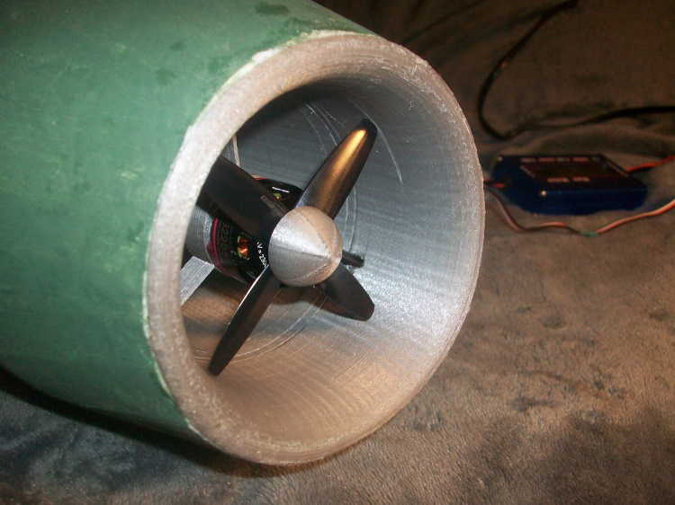
With a small printed make up piece I was able to insert the new bell mouth (its exactly the same as the old one) with the motor directly into the existing duct. A great relief as I thought it was going to require some major surgery.
The view up the exhaust showing the stream lined 'after body' attached to the back of the motor.

It certainly seems to have made a difference. A short run using the 850 mAh 5s (from the V-2) ran up smoothly drawing 12.3 A and 212 W. Just over double! I don't know how many of those extra Watts are turned into thrust but there were no strange noises in the duct - apart from the scream of the motor! :woohoo:
So the first objective has been achieved, 100W/lb, in fact its now closer to 150!
Next is the tricky bit reorganising everything to achieve the required CofG.
Nevertheless 'So far so good.'
With a small printed make up piece I was able to insert the new bell mouth (its exactly the same as the old one) with the motor directly into the existing duct. A great relief as I thought it was going to require some major surgery.
The view up the exhaust showing the stream lined 'after body' attached to the back of the motor.
It certainly seems to have made a difference. A short run using the 850 mAh 5s (from the V-2) ran up smoothly drawing 12.3 A and 212 W. Just over double! I don't know how many of those extra Watts are turned into thrust but there were no strange noises in the duct - apart from the scream of the motor! :woohoo:
So the first objective has been achieved, 100W/lb, in fact its now closer to 150!
Next is the tricky bit reorganising everything to achieve the required CofG.
Nevertheless 'So far so good.'
Thanks: Klipkopwildlife, Flytilbroke, THE BLACKBIRD, paul d, crash happy
Please Log in or Create an account to join the conversation.
- Klipkopwildlife
-
- Offline
- Administrator
-
- I'm supposed to be retired!
09 Apr 2021 07:49 #189
by Klipkopwildlife
Do it now, you may never get another chance
Replied by Klipkopwildlife on topic Depron Heinkel HE162
A lesson learned here Simon, it's easier to take air and push it down a tube, than it is to pull it down a tube and push it into the open air. Given that air is normally at about 14.5psi, I'm guessing that your air pressure was considerably less than that by the time it got to your propeller.
Do it now, you may never get another chance
Thanks: crash happy
Please Log in or Create an account to join the conversation.
- paul d
-
- Offline
- Forum Veteran
-
Less
More
- Posts: 2074
- Thank you received: 2292
09 Apr 2021 08:15 #190
by paul d
Thanks: Klipkopwildlife
Please Log in or Create an account to join the conversation.
- Quorneng
-
Topic Author
- Offline
- Forum Master
-
Less
More
- Posts: 9436
- Thank you received: 19043
09 Apr 2021 20:21 #191
by Quorneng
Replied by Quorneng on topic Depron Heinkel HE162
One step forward one step back.
I tried the nacelle on the 5s again but this time fully charged.
Ran up to speed no problem but after just a few seconds I noticed a slight haze in the exhaust! :woohoo:
Instant shut down but as it slowed down the fan was rubbing on the duct. Placed a finger onto the motor but it was quickly withdrawn however it did explain why the blades were rubbing. The motor had softened the PLA motor mount. :ohmy:
After it had cooled down (with the prop held central) I tested the motor but it is kaput!
I have a spare so had to cut the motor out, again! This time at least I knew exactly where to cut.
It needed a new duct 'make up' piece printing but it all went back together in less that 2 hours.

Of course these motors are bought in pairs so the spare is the opposite hand (CCW) with a prop to suit.
It would appear 4s is the practical limit for this motor and prop combination. Not too much of a disaster as 'prop at front' does deliver a bit more thrust than it had before.
Onwards and upwards.
I tried the nacelle on the 5s again but this time fully charged.
Ran up to speed no problem but after just a few seconds I noticed a slight haze in the exhaust! :woohoo:
Instant shut down but as it slowed down the fan was rubbing on the duct. Placed a finger onto the motor but it was quickly withdrawn however it did explain why the blades were rubbing. The motor had softened the PLA motor mount. :ohmy:
After it had cooled down (with the prop held central) I tested the motor but it is kaput!
I have a spare so had to cut the motor out, again! This time at least I knew exactly where to cut.
It needed a new duct 'make up' piece printing but it all went back together in less that 2 hours.
Of course these motors are bought in pairs so the spare is the opposite hand (CCW) with a prop to suit.
It would appear 4s is the practical limit for this motor and prop combination. Not too much of a disaster as 'prop at front' does deliver a bit more thrust than it had before.
Onwards and upwards.
Thanks: Eric, Klipkopwildlife, Flytilbroke, paul d, crash happy
Please Log in or Create an account to join the conversation.
- Quorneng
-
Topic Author
- Offline
- Forum Master
-
Less
More
- Posts: 9436
- Thank you received: 19043
11 Apr 2021 23:38 - 11 Apr 2021 23:40 #192
by Quorneng
Replied by Quorneng on topic Depron Heinkel HE162
Next to start work on rearranging the fuselage.
I guestimate the battery will go about in the cockpit area so the canopy might just as well be made removable to get at it!
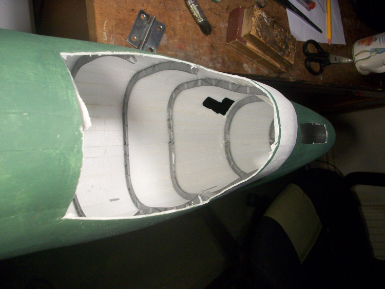
With everything that was in the nose removed it suddenly gets very empty.
The stab Rx with be moved to under the wing. This picture shows not only shows the excess servo wire that will be made redundant but also the extremely small size of the ESC and SBEC!

To restore the fuselage torsional rigidity around the canopy area the cockpit will have a fully skinned interior.
I guestimate the battery will go about in the cockpit area so the canopy might just as well be made removable to get at it!
With everything that was in the nose removed it suddenly gets very empty.
The stab Rx with be moved to under the wing. This picture shows not only shows the excess servo wire that will be made redundant but also the extremely small size of the ESC and SBEC!
To restore the fuselage torsional rigidity around the canopy area the cockpit will have a fully skinned interior.
Last edit: 11 Apr 2021 23:40 by Quorneng.
Thanks: Eric, Klipkopwildlife, crash happy
Please Log in or Create an account to join the conversation.
- Quorneng
-
Topic Author
- Offline
- Forum Master
-
Less
More
- Posts: 9436
- Thank you received: 19043
15 Apr 2021 23:26 #193
by Quorneng
Replied by Quorneng on topic Depron Heinkel HE162
The removable cockpit canopy is now has stand lone framing.

Matching frames in the fuselage give a reasonably good fit.
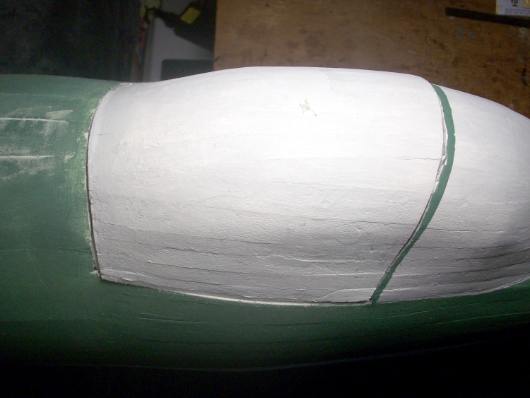
Under the canopy is a big battery compartment courtesy of my copious supply of 5 mm grey polystyrene foam floor insulation.

Actually its main purpose is to restore the fuselage torsional rigidity now the canopy is removeable however the volume is big enough to not only hold the battery but the ESC and SBEC as well.
Matching frames in the fuselage give a reasonably good fit.
Under the canopy is a big battery compartment courtesy of my copious supply of 5 mm grey polystyrene foam floor insulation.
Actually its main purpose is to restore the fuselage torsional rigidity now the canopy is removeable however the volume is big enough to not only hold the battery but the ESC and SBEC as well.
Thanks: Eric, Klipkopwildlife, THE BLACKBIRD, paul d, crash happy
Please Log in or Create an account to join the conversation.
- Quorneng
-
Topic Author
- Offline
- Forum Master
-
Less
More
- Posts: 9436
- Thank you received: 19043
25 Apr 2021 21:19 - 25 Apr 2021 21:21 #194
by Quorneng
Replied by Quorneng on topic Depron Heinkel HE162
Despite spending time mending other planes and laying paviers for my daughter I have continued slowly with the HE 162.
The ESC and UBEC are all wired up and glued to the cockpit floor.

The observant may notice that the ESC is wired for Deans but the 650mAh 4s has an XT30. :woohoo:
I think in this application the XT30 is more appropriate so the ESC will be changed have my first ever one!
The Lemon 'stab' is placed under the wing close to the CofG however being a 'rate only' gyro it position is not critical. It just has to align with the plane's fore and aft axis.

Not yet fixed its position is chosen to minimises servo wire length. It will use its 'dual ail' option so the differential ailerons function can be set up on the Tx.
The last bit is a printed brace to support the duct close under the motor.
The front duct pylon is quite narrow. This was not a problem when the motor was at the back as the rear duct pylon is quite broad but with the motor now at the front extra support is needed.
Slowly getting there.
The ESC and UBEC are all wired up and glued to the cockpit floor.
The observant may notice that the ESC is wired for Deans but the 650mAh 4s has an XT30. :woohoo:
I think in this application the XT30 is more appropriate so the ESC will be changed have my first ever one!
The Lemon 'stab' is placed under the wing close to the CofG however being a 'rate only' gyro it position is not critical. It just has to align with the plane's fore and aft axis.
Not yet fixed its position is chosen to minimises servo wire length. It will use its 'dual ail' option so the differential ailerons function can be set up on the Tx.
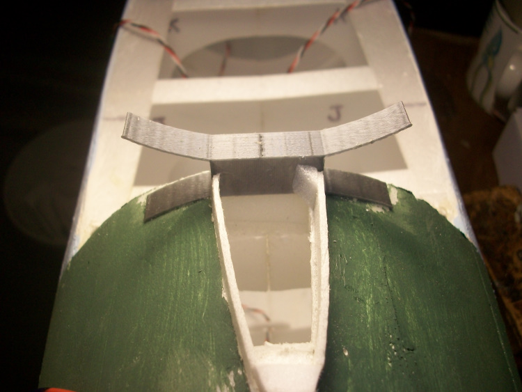
The last bit is a printed brace to support the duct close under the motor.
The front duct pylon is quite narrow. This was not a problem when the motor was at the back as the rear duct pylon is quite broad but with the motor now at the front extra support is needed.
Slowly getting there.
Last edit: 25 Apr 2021 21:21 by Quorneng.
Thanks: Klipkopwildlife, THE BLACKBIRD, Ralpharr2001, crash happy
Please Log in or Create an account to join the conversation.
- Quorneng
-
Topic Author
- Offline
- Forum Master
-
Less
More
- Posts: 9436
- Thank you received: 19043
30 Apr 2021 22:26 #195
by Quorneng
Replied by Quorneng on topic Depron Heinkel HE162
Finally the fuselage is now complete - again!
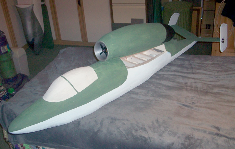
The final job left to do is to separate the aileron servo wires as they exit the wing, they are currently on a Y lead, to pick up the 'dual ail' setup on the receiver.
As the duct has been completely refitted it will require a test fit the wing.
The elevator gyro response is ok as I have tested it but the 'dual ail' function is new so it may not be.
Strong winds and heavy rain forecast for the bank holiday.
Thanks: Klipkopwildlife, Flytilbroke, THE BLACKBIRD, Ralpharr2001, crash happy
Please Log in or Create an account to join the conversation.
Time to create page: 1.311 seconds