
- Posts: 10058
- Thank you received: 19042
3D printing Widgets
- Quorneng
-

- Offline
- Forum Master
-

Less
More
26 Jun 2022 18:56 #31
by Quorneng
Replied by Quorneng on topic 3D printing Widgets
jon
That's very neat.
I suppose the only weak point is how well the bolts will survive in the printed body. The bolts are plenty strong enough but it will put the printed plastic under quite a bit of load over the threaded portion.
That 1806, like many such motors are intended as a quad copter motor where a nut prop mounting is ideal.
That's very neat.
I suppose the only weak point is how well the bolts will survive in the printed body. The bolts are plenty strong enough but it will put the printed plastic under quite a bit of load over the threaded portion.
That 1806, like many such motors are intended as a quad copter motor where a nut prop mounting is ideal.
Thanks: jon.in.swansea
Please Log in or Create an account to join the conversation.
- jon.in.swansea
-

- Offline
- Elite Member
-

Less
More
- Posts: 750
- Thank you received: 1147
26 Jun 2022 19:35 #32
by jon.in.swansea
Replied by jon.in.swansea on topic 3D printing Widgets
We will see how well that motor and prop saver works once I put together my next idea for a minimalist fuselage.
I have the option to print it with a higher proportion of 'infil' and also to increase the size of the main body a bit. -Jon
I have the option to print it with a higher proportion of 'infil' and also to increase the size of the main body a bit. -Jon
Please Log in or Create an account to join the conversation.
- jon.in.swansea
-
- Offline
- Elite Member
-
Less
More
- Posts: 750
- Thank you received: 1147
13 Jul 2022 10:35 #33
by jon.in.swansea
Replied by jon.in.swansea on topic 3D printing Widgets
Here is another useful widget - a longer servo arm for a sg90 servo. In putting together another hybrid Clarke-Y wing I found that the standard servo arm for the aileron was rather short and would have needed the linkage to disappear into the wing at the extents of travel.
In my collection of STLs I found a collection of servo arms of various types. I test printed one arm and found a minor tweak in scale it would fit on the servo I was using. I then imported that STL into freeCAD, converted it to a solid and then added a rectangular body to extend it and subtracted a couple of holes. I printed a set 3 layers base, 3 layers top, 2 perimeters, 30% fill. It only takes a few minutes.
I know that PLA is perhaps not optimal. We shall see if it needs a bit more thickness or additional reinforcement. The nice thing about it is that the STL should be scalable to fit other servos - I keep finding that servos and spare arms tend to displace to parallel universes.

And here is preview of a set of arms about to be printed....

Here is a comparison of standard and extended arm....

Here is the freeCAD file:
And here is the STL file:
I found the original STL on the Prusa site:

In my collection of STLs I found a collection of servo arms of various types. I test printed one arm and found a minor tweak in scale it would fit on the servo I was using. I then imported that STL into freeCAD, converted it to a solid and then added a rectangular body to extend it and subtracted a couple of holes. I printed a set 3 layers base, 3 layers top, 2 perimeters, 30% fill. It only takes a few minutes.
I know that PLA is perhaps not optimal. We shall see if it needs a bit more thickness or additional reinforcement. The nice thing about it is that the STL should be scalable to fit other servos - I keep finding that servos and spare arms tend to displace to parallel universes.
And here is preview of a set of arms about to be printed....
Here is a comparison of standard and extended arm....
Here is the freeCAD file:
This attachment is hidden for guests.
Please log in or register to see it.
Please log in or register to see it.
And here is the STL file:
This attachment is hidden for guests.
Please log in or register to see it.
Please log in or register to see it.
I found the original STL on the Prusa site:
Attachments:
Thanks: Klipkopwildlife
Please Log in or Create an account to join the conversation.
- Klipkopwildlife
-
 Topic Author
- Offline
- Administrator
-

- I'm supposed to be retired!
13 Jul 2022 10:57 #34
by Klipkopwildlife
Do it now, you may never get another chance
Replied by Klipkopwildlife on topic 3D printing Widgets
It'll be plenty strong enough Jon, it doesn't get very hot out at that end of the wing.![[badass]](/media/kunena/emoticons/bad_boys_20.gif "[badass]")
Do it now, you may never get another chance
Please Log in or Create an account to join the conversation.
- Quorneng
-
- Offline
- Forum Master
-
Less
More
- Posts: 10058
- Thank you received: 19042
13 Jul 2022 16:05 - 13 Jul 2022 16:11 #35
by Quorneng
Replied by Quorneng on topic 3D printing Widgets
The arms will be plenty strong enough. My concern would be the printer's ability to generate the fine splines on the inside of the hub to match those on the servo output shaft. They have to be a really accurate match to handle the torque.
Does the arm even have splines? I would have thought just relying on it being a 'tight' fit would be asking for trouble.
To make matters worse not all manufacturers use the same number of splines for a particular size of servo as a way to ensure you have to buy their servo arms.
Does the arm even have splines? I would have thought just relying on it being a 'tight' fit would be asking for trouble.
To make matters worse not all manufacturers use the same number of splines for a particular size of servo as a way to ensure you have to buy their servo arms.
Last edit: 13 Jul 2022 16:11 by Quorneng.
Thanks: Eric, Klipkopwildlife, jon.in.swansea
Please Log in or Create an account to join the conversation.
- jon.in.swansea
-
- Offline
- Elite Member
-
Less
More
- Posts: 750
- Thank you received: 1147
13 Jul 2022 18:59 #36
by jon.in.swansea
Replied by jon.in.swansea on topic 3D printing Widgets
There are no splines on the arm. I managed to find a scale on the printer which, given a strong press fit seems to result in no play when screwed in. I suppose with my Lupe I could count the splines and see if I could introduce something but for now I will see how well it holds up in testing.
I remember Simon created a slip-over extension for an existing arm that was brute-force glued (nylon not really something that glue will attach to). That also might be a way forward if this proves to be less than adequate. -Jon
I remember Simon created a slip-over extension for an existing arm that was brute-force glued (nylon not really something that glue will attach to). That also might be a way forward if this proves to be less than adequate. -Jon
Thanks: Klipkopwildlife
Please Log in or Create an account to join the conversation.
- Eric
-

- Offline
- Moderator
-

Less
More
- Posts: 15334
- Thank you received: 14141
13 Jul 2022 20:31 #37
by Eric
if you are calm and collected when all about you are going berserk - you've missed something important!
Replied by Eric on topic 3D printing Widgets
Press-fit servo arms possibly won't work very reliably. Under load, the arm can slip on the effectively round output shaft of the servo - giving you unpredictable trim errors between, and even in, flight.
if you are calm and collected when all about you are going berserk - you've missed something important!
Thanks: Klipkopwildlife
Please Log in or Create an account to join the conversation.
- Quorneng
-
- Offline
- Forum Master
-
Less
More
- Posts: 10058
- Thank you received: 19042
14 Jul 2022 01:32 #38
by Quorneng
Replied by Quorneng on topic 3D printing Widgets
Just for completeness the TOWER PRO SG90 has a 21 spline output shaft (if I counted them right) and the supplied nylon arms have matching splined hubs.
The retaining screw thus only holds the arm in place and does not contribute to the ability of the arm to resist the servo torque.
The retaining screw thus only holds the arm in place and does not contribute to the ability of the arm to resist the servo torque.
Thanks: Klipkopwildlife, jon.in.swansea
Please Log in or Create an account to join the conversation.
- jon.in.swansea
-
- Offline
- Elite Member
-
Less
More
- Posts: 750
- Thank you received: 1147
14 Jul 2022 08:00 #39
by jon.in.swansea
Replied by jon.in.swansea on topic 3D printing Widgets
Thanks for counting. My servo seems to be 22. No idea yet how to get that kind of small detail into
the CAD but there must be a way....
I have done a look-up of aileron mechanical differential and I have a plan to revise the arm position and
the aileron horn. I will do a quick film of the movements and measure the angles to see what gets the down angle to
~half of the up and link to that for comment.
the CAD but there must be a way....
I have done a look-up of aileron mechanical differential and I have a plan to revise the arm position and
the aileron horn. I will do a quick film of the movements and measure the angles to see what gets the down angle to
~half of the up and link to that for comment.
Thanks: Klipkopwildlife
Please Log in or Create an account to join the conversation.
- Eric
-
- Offline
- Moderator
-
Less
More
- Posts: 15334
- Thank you received: 14141
14 Jul 2022 09:24 - 14 Jul 2022 09:33 #40
by Eric
if you are calm and collected when all about you are going berserk - you've missed something important!
Replied by Eric on topic 3D printing Widgets
Here's a rough sketch of what I was trying to explain in words -
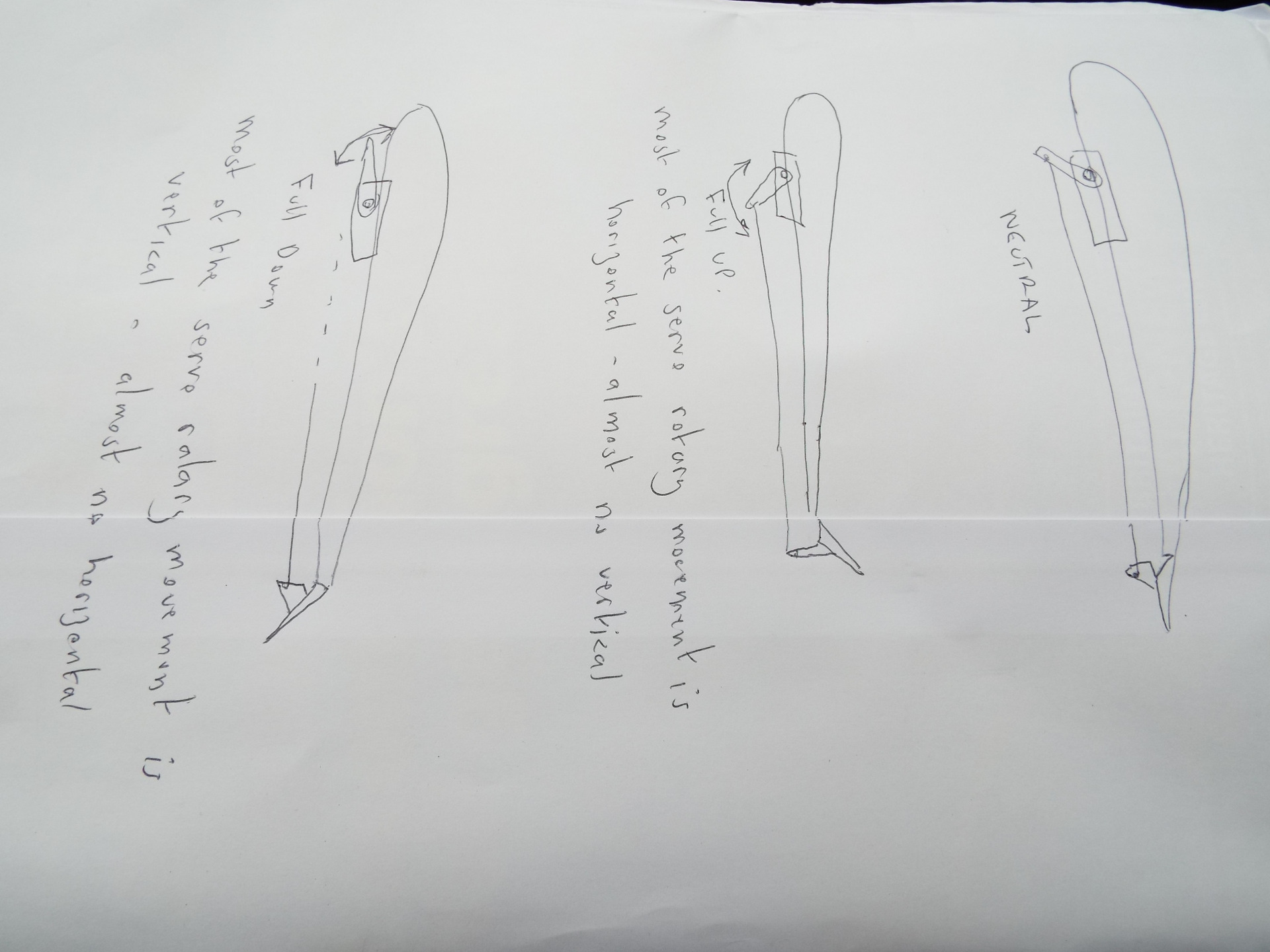
With the servo mounted underneath the wing, set the servo arm at roughly 45' forwards with the servo in the neutral position.
The holes in the control horn should be in line with the hinge on the surface.
So -
With full servo deflection in the upward direction, most of the pushrod movement is horizontal, with a smll amount of vertical.
BUT
With full servo deflection in the downward direction, most of the pushrod movement is vertical, with little horizontal movement.
For a top-mounted servo (looks untidy!) the servo arm should be tilted 45' AFT in the neutral position, to give the same surface movements.
With the servo mounted underneath the wing, set the servo arm at roughly 45' forwards with the servo in the neutral position.
The holes in the control horn should be in line with the hinge on the surface.
So -
With full servo deflection in the upward direction, most of the pushrod movement is horizontal, with a smll amount of vertical.
BUT
With full servo deflection in the downward direction, most of the pushrod movement is vertical, with little horizontal movement.
For a top-mounted servo (looks untidy!) the servo arm should be tilted 45' AFT in the neutral position, to give the same surface movements.
if you are calm and collected when all about you are going berserk - you've missed something important!
Attachments:
Last edit: 14 Jul 2022 09:33 by Eric. Reason: added text
Thanks: Klipkopwildlife, jon.in.swansea
Please Log in or Create an account to join the conversation.
- Eric
-
- Offline
- Moderator
-
Less
More
- Posts: 15334
- Thank you received: 14141
14 Jul 2022 09:39 #41
by Eric
if you are calm and collected when all about you are going berserk - you've missed something important!
Replied by Eric on topic 3D printing Widgets
Having posted that, I see that Simon has offered a better drawing on the other thread! 
if you are calm and collected when all about you are going berserk - you've missed something important!
Thanks: Klipkopwildlife
Please Log in or Create an account to join the conversation.
- jon.in.swansea
-
- Offline
- Elite Member
-
Less
More
- Posts: 750
- Thank you received: 1147
14 Jul 2022 12:21 #42
by jon.in.swansea
Replied by jon.in.swansea on topic 3D printing Widgets
Thanks for the sketch!
Thanks: Eric
Please Log in or Create an account to join the conversation.
- jon.in.swansea
-
- Offline
- Elite Member
-
Less
More
- Posts: 750
- Thank you received: 1147
14 Jul 2022 12:26 - 14 Jul 2022 14:17 #43
by jon.in.swansea
Replied by jon.in.swansea on topic 3D printing Widgets
I did a bit more looking around for printable servo arms. It turns out there is a collection of the beasties for the Tower Pro SG90 that gets around the fine indentations by slipping on top of the existing arm....
3dmixers.com/m/28751-sg90-armhorn-extenderdifferent-sizes
Here is what it looks like. I did a quick print and it is an amazingly tight fit, no glue is going to be needed.

Shown is a 5mm 10mm and 15mm extension. There are variants that go up to 50mm. Amazing
what can be found out there if you keep looking. Also it is so nice to find a work-around for
their 'you have to buy our stuff'. -Jon
3dmixers.com/m/28751-sg90-armhorn-extenderdifferent-sizes
Here is what it looks like. I did a quick print and it is an amazingly tight fit, no glue is going to be needed.
Shown is a 5mm 10mm and 15mm extension. There are variants that go up to 50mm. Amazing
what can be found out there if you keep looking. Also it is so nice to find a work-around for
their 'you have to buy our stuff'. -Jon
Attachments:
Last edit: 14 Jul 2022 14:17 by Klipkopwildlife.
Thanks: Eric, Klipkopwildlife, Quorneng
Please Log in or Create an account to join the conversation.
- Klipkopwildlife
-
Topic Author
- Offline
- Administrator
-
- I'm supposed to be retired!
14 Jul 2022 14:19 #44
by Klipkopwildlife
Do it now, you may never get another chance
Replied by Klipkopwildlife on topic 3D printing Widgets
I would have thought you could put the arm on, screw it down then give it a light blow with a hair dryer or electric paint stripper. At about 140o the PLA should deform enough to create its own splines.
Do it now, you may never get another chance
Please Log in or Create an account to join the conversation.
- Quorneng
-
- Offline
- Forum Master
-
Less
More
- Posts: 10058
- Thank you received: 19042
14 Jul 2022 14:51 #45
by Quorneng
Replied by Quorneng on topic 3D printing Widgets
I fear you would need a very accurate hot air blow otherwise you risk deforming the arm itself.
It would certainly work if the servo shaft was brass and you touched with a soldering iron but unfortunately the SG90 shaft is nylon.
I do think a printed clip on arm 'sleeve' is the most practical solution.
It would certainly work if the servo shaft was brass and you touched with a soldering iron but unfortunately the SG90 shaft is nylon.
I do think a printed clip on arm 'sleeve' is the most practical solution.
Thanks: Eric, Klipkopwildlife, jon.in.swansea
Please Log in or Create an account to join the conversation.
Time to create page: 1.565 seconds