
- Posts: 750
- Thank you received: 1147
3D printing Widgets
- jon.in.swansea
-

- Offline
- Elite Member
-

Less
More
16 Oct 2024 14:54 #91
by jon.in.swansea
Replied by jon.in.swansea on topic 3D printing Widgets
There has been some progress on the Swansea workshop/man-cave. I took delivery of an all-metal workbench with a solid wood top and put the bits together yesterday. There was a version just the length (1.7m). Drawers and cabinets for tools. Solid beastie. Goodness prices are crazy these days for such things - but a big step up in function from using a gate-leg table in my office. However it is really humid in the workshop (it was used for years as a dog grooming business) so have ordered a dehumidifier (or I will have endless issues with damp filament).
Shelving should arrive for assembly next week and that should get the other boxes littering the space sorted. Then I should be in a position to order a new 3D printer (the Prusa Mini is in a plastic shroud on the left of the workbench awaiting dryer conditions). Tony has had such good luck with his Prusa 4 I am looking at the Prusa 4S. And then I can re-start RC projects. I have in mind hybrid wings with foam skin over LWPLA ribs, CF spar to go with the fuse designs I was looking at a year ago.... LWPLA skin can't take the 'oops' that a foam skin can.
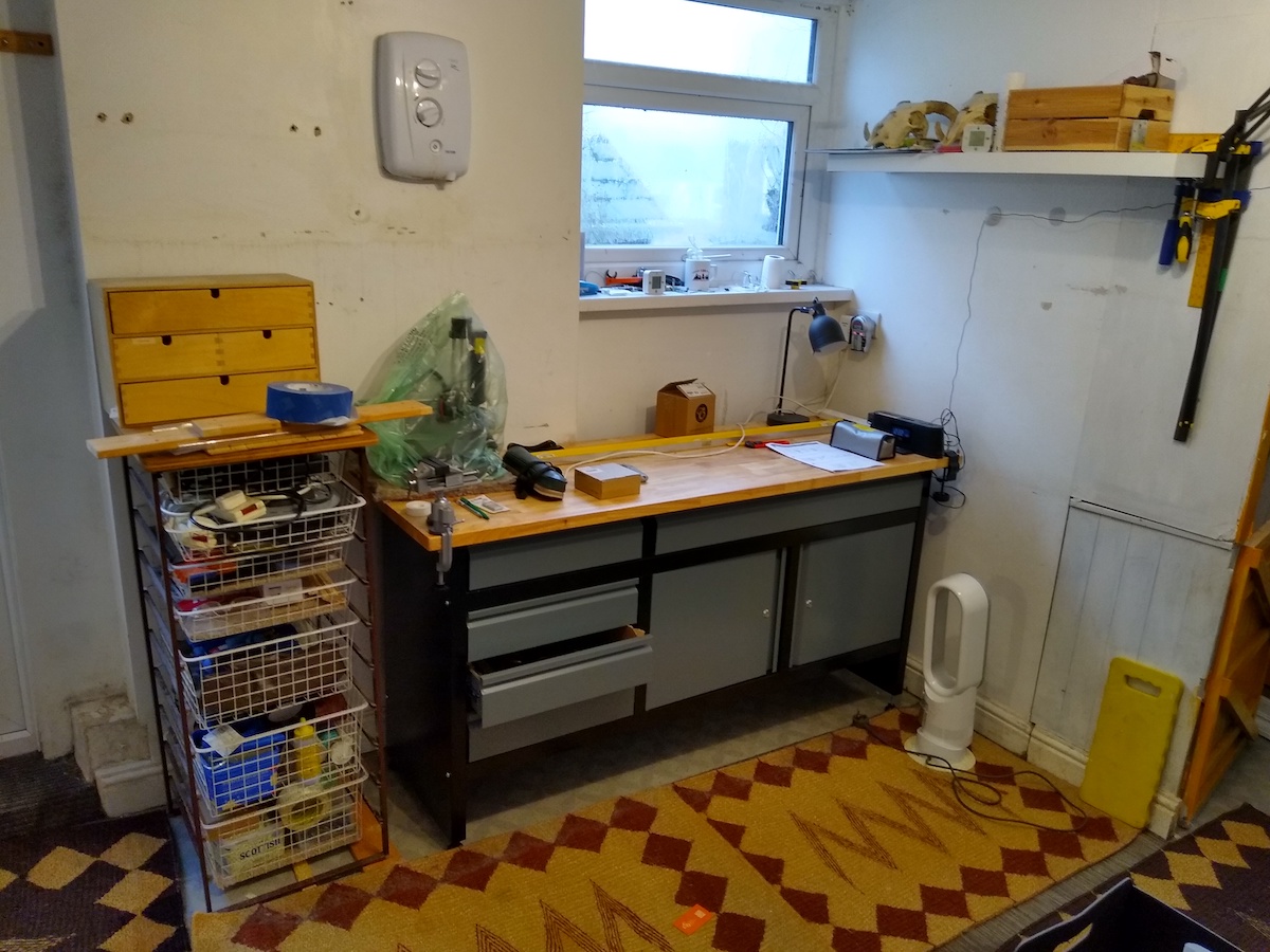
Shelving should arrive for assembly next week and that should get the other boxes littering the space sorted. Then I should be in a position to order a new 3D printer (the Prusa Mini is in a plastic shroud on the left of the workbench awaiting dryer conditions). Tony has had such good luck with his Prusa 4 I am looking at the Prusa 4S. And then I can re-start RC projects. I have in mind hybrid wings with foam skin over LWPLA ribs, CF spar to go with the fuse designs I was looking at a year ago.... LWPLA skin can't take the 'oops' that a foam skin can.
Attachments:
Thanks: Klipkopwildlife, Flytilbroke
Please Log in or Create an account to join the conversation.
- Quorneng
-

- Offline
- Forum Master
-

Less
More
- Posts: 10058
- Thank you received: 19042
16 Oct 2024 17:07 #92
by Quorneng
Replied by Quorneng on topic 3D printing Widgets
jon
Nothing wrong with a thin foam skin over printed ribs.
Don't be shy to make the ribs strong enough to resist "handling" loads. These are likely to be locally many times more severe than anything aerodynamic.
It was one reason I went from PLA to LW-PLA. ribs. The basically lighter material allowed more material to be used to resist a misplaced figure grip crushing a rib.
Nothing wrong with a thin foam skin over printed ribs.
Don't be shy to make the ribs strong enough to resist "handling" loads. These are likely to be locally many times more severe than anything aerodynamic.
It was one reason I went from PLA to LW-PLA. ribs. The basically lighter material allowed more material to be used to resist a misplaced figure grip crushing a rib.
Thanks: Klipkopwildlife, jon.in.swansea
Please Log in or Create an account to join the conversation.
- jon.in.swansea
-
- Offline
- Elite Member
-
Less
More
- Posts: 750
- Thank you received: 1147
23 Dec 2024 13:31 #93
by jon.in.swansea
Replied by jon.in.swansea on topic 3D printing Widgets
In the general discussion of using CAD for RC work I recently came across a video where someone was showing how they photograph an artefact (usually including a tape measure in the image) and then use a FreeCAD option to calibrate the image to the measure. One then sketches a new design over the scaled image.
I tried this in the context of a bit of stone wall and a piece of slate that I wanted to make into a street number display. I needed to design a support which would have holes that lined up with the gaps in the stone wall but also fit snuggly to the slate. Images below of that process. In the top image is a photo of the wall and with a double click on the image the calibrate option pops up. You pick two points on the image and give it a length. On top of this is a draft support to plan out where the support holes should be.

In this image I have the photo of the slate as well as the draft support.

After trying different options to coordinate between the two sets of constraints. I printed the support and took it out and then found there was a slightly better location for it.
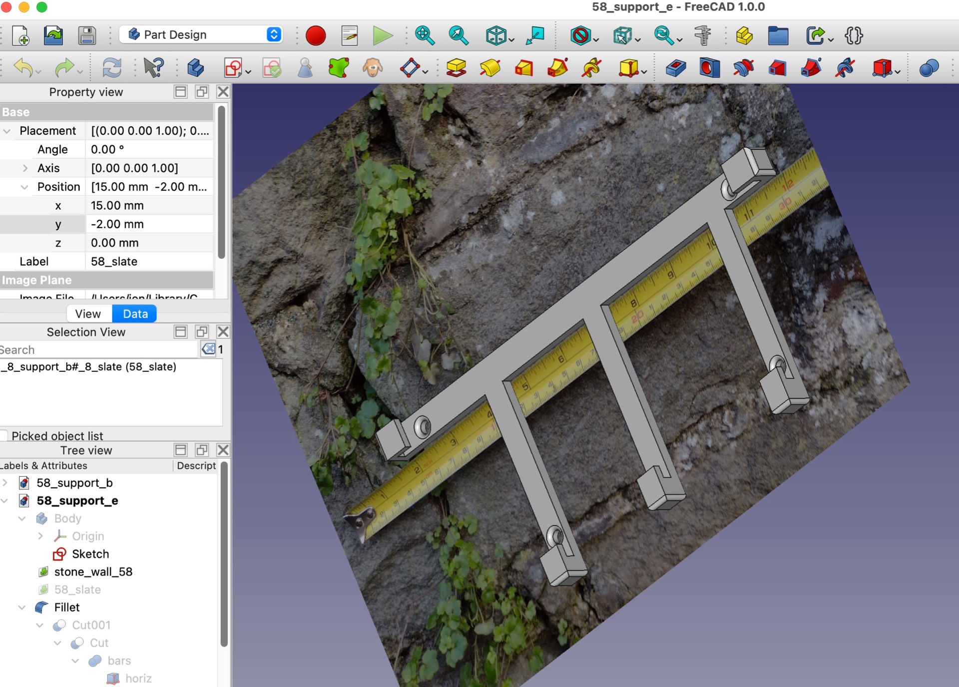
In a RC context, one could photograph parts of an existing model or perhaps an old faded plan from a balsa kit and then 'calibrate' the photo and then create a new part(s) that should fit very tightly. Just be sure to take the photo at right angles to the item to get the best chance of matching. Less need to set calipers on scores of places.
I tried this in the context of a bit of stone wall and a piece of slate that I wanted to make into a street number display. I needed to design a support which would have holes that lined up with the gaps in the stone wall but also fit snuggly to the slate. Images below of that process. In the top image is a photo of the wall and with a double click on the image the calibrate option pops up. You pick two points on the image and give it a length. On top of this is a draft support to plan out where the support holes should be.
In this image I have the photo of the slate as well as the draft support.
After trying different options to coordinate between the two sets of constraints. I printed the support and took it out and then found there was a slightly better location for it.
In a RC context, one could photograph parts of an existing model or perhaps an old faded plan from a balsa kit and then 'calibrate' the photo and then create a new part(s) that should fit very tightly. Just be sure to take the photo at right angles to the item to get the best chance of matching. Less need to set calipers on scores of places.
Attachments:
Thanks: Klipkopwildlife, Flytilbroke, Quorneng
Please Log in or Create an account to join the conversation.
- Klipkopwildlife
-
 Topic Author
- Offline
- Administrator
-

- I'm supposed to be retired!
24 Dec 2024 12:47 #94
by Klipkopwildlife
Do it now, you may never get another chance
Replied by Klipkopwildlife on topic 3D printing Widgets
Thanks Jon, the things you find never cease to amaze me.
On another note, where do you find the system presets for the mk4S? Mine still show me mk4?
On another note, where do you find the system presets for the mk4S? Mine still show me mk4?
Do it now, you may never get another chance
Thanks: jon.in.swansea
Please Log in or Create an account to join the conversation.
- jon.in.swansea
-
- Offline
- Elite Member
-
Less
More
- Posts: 750
- Thank you received: 1147
25 Dec 2024 17:03 #95
by jon.in.swansea
Replied by jon.in.swansea on topic 3D printing Widgets
As the MK4S is a different printer than a MK4 you need to select a MK4S as a new printer type.
Find the top level tab 'printers' and in the pull down the 'add/delete printer'. That should pull
up a list of lots of different printers from Prusa and elsewhere.
Find the top level tab 'printers' and in the pull down the 'add/delete printer'. That should pull
up a list of lots of different printers from Prusa and elsewhere.
Thanks: Klipkopwildlife, Flytilbroke
Please Log in or Create an account to join the conversation.
- Klipkopwildlife
-
Topic Author
- Offline
- Administrator
-
- I'm supposed to be retired!
26 Dec 2024 17:00 #96
by Klipkopwildlife
Do it now, you may never get another chance
Replied by Klipkopwildlife on topic 3D printing Widgets
Thanks Jon, it all came together when I went to Configuration and told it to download everything. The first thing I noticed is the 4S version doesn't have the Input shaper option.
Do it now, you may never get another chance
Thanks: jon.in.swansea
Please Log in or Create an account to join the conversation.
- jon.in.swansea
-
- Offline
- Elite Member
-
Less
More
- Posts: 750
- Thank you received: 1147
29 Dec 2024 14:02 #97
by jon.in.swansea
Replied by jon.in.swansea on topic 3D printing Widgets
With the MK4S I think that input shaper is the default rather than an option.
Thanks: Klipkopwildlife
Please Log in or Create an account to join the conversation.
- jon.in.swansea
-
- Offline
- Elite Member
-
Less
More
- Posts: 750
- Thank you received: 1147
31 Dec 2024 14:49 #98
by jon.in.swansea
Replied by jon.in.swansea on topic 3D printing Widgets
Since it is gusting to 50MPH outside no one is going to be flying RC today.... so some 'closure' on the CAD use of images to scale printed parts....
I printed out the support structure and took it and the slate out to the street entry/stair with 'the boss' and the place where I had carefully planned the attachment was vetoed. "Needs to be a bit lower and to the left". That bit was rather more challenging as the stone face was much more rustic. So I took callipers and measured for stand-offs. A quick print and then drill out the stone for RAL plugs and presto ands tree number sign from found bits of slate, printed numbers and support.



I printed out the support structure and took it and the slate out to the street entry/stair with 'the boss' and the place where I had carefully planned the attachment was vetoed. "Needs to be a bit lower and to the left". That bit was rather more challenging as the stone face was much more rustic. So I took callipers and measured for stand-offs. A quick print and then drill out the stone for RAL plugs and presto ands tree number sign from found bits of slate, printed numbers and support.
Attachments:
Thanks: Klipkopwildlife, Flytilbroke, Quorneng
Please Log in or Create an account to join the conversation.
- jon.in.swansea
-
- Offline
- Elite Member
-
Less
More
- Posts: 750
- Thank you received: 1147
21 Feb 2025 11:57 - 21 Feb 2025 11:59 #99
by jon.in.swansea
Replied by jon.in.swansea on topic 3D printing Widgets
CAD related post for folk who are trying to work with an imported STL file....One of the recurring irritants of importing STL files into CAD applications is the tendency of the mesh of the wing or fuse etc. to show up at some distance from the CAD origin. Even those who are experts in FreeCAD are slowed down by this.
This video explores two different workflows, one using the Manipulator Workbench. Many of you would have gone down lots of rabbit-holes on this. I found a singular combination of toggles and selections that gets bodies derived from a STL mesh into a position of your choice. Mind you you still have to do some extreme zooms to ensure correct identification of the reference and body to move.
I spent so many hours not getting the CAD to work it might save others lots of hassle. Broadly applicable so hopefully other aero groups will pick up on it.
This video explores two different workflows, one using the Manipulator Workbench. Many of you would have gone down lots of rabbit-holes on this. I found a singular combination of toggles and selections that gets bodies derived from a STL mesh into a position of your choice. Mind you you still have to do some extreme zooms to ensure correct identification of the reference and body to move.
I spent so many hours not getting the CAD to work it might save others lots of hassle. Broadly applicable so hopefully other aero groups will pick up on it.
Last edit: 21 Feb 2025 11:59 by jon.in.swansea.
Thanks: Klipkopwildlife, Quorneng
Please Log in or Create an account to join the conversation.
- jon.in.swansea
-
- Offline
- Elite Member
-
Less
More
- Posts: 750
- Thank you received: 1147
28 Feb 2025 17:20 #100
by jon.in.swansea
Replied by jon.in.swansea on topic 3D printing Widgets
Next in the series. Worked out how to take a complex wing form STL and
revise it so it can be vase printed. A variation of the creation of a set of
ribs. Added step of slightly offsetting the ribs or spars by 0.5mm so that
when they are cut from the wing you get something that the 3D slicer
will interpret so as to allow a vase mode print or at least a single perimeter
print with almost zero internal cruft and lighter weight and seems like the
same stiffness as a gyroid fill.
Here is the link....
_________________A video exploring converting from gyroid infil to vase-mode spars in RC model wingsIn a prior video I looked at creating a series of ribs which match a complex wing form. In this video we use a similar workflow but with an added offset to cut away spar shapes from a complex wing form. Not only is the wing printable in vase mode or a single perimeter almost-vase mode it seems to be equally stiff, lighter weight and faster to print.The video reviews three possible workflows in FreeCAD and then works through a session using the the curves workbench and the slice-apart function to create an STL and preview within the slicer.
revise it so it can be vase printed. A variation of the creation of a set of
ribs. Added step of slightly offsetting the ribs or spars by 0.5mm so that
when they are cut from the wing you get something that the 3D slicer
will interpret so as to allow a vase mode print or at least a single perimeter
print with almost zero internal cruft and lighter weight and seems like the
same stiffness as a gyroid fill.
Here is the link....
_________________A video exploring converting from gyroid infil to vase-mode spars in RC model wingsIn a prior video I looked at creating a series of ribs which match a complex wing form. In this video we use a similar workflow but with an added offset to cut away spar shapes from a complex wing form. Not only is the wing printable in vase mode or a single perimeter almost-vase mode it seems to be equally stiff, lighter weight and faster to print.The video reviews three possible workflows in FreeCAD and then works through a session using the the curves workbench and the slice-apart function to create an STL and preview within the slicer.
Thanks: Klipkopwildlife
Please Log in or Create an account to join the conversation.
- Quorneng
-
- Offline
- Forum Master
-
Less
More
- Posts: 10058
- Thank you received: 19042
28 Feb 2025 21:52 - 28 Feb 2025 21:53 #101
by Quorneng
Replied by Quorneng on topic 3D printing Widgets
All I can say is Wow!
Techniques miles beyond anything I can do.
My on;y observation is printing does have a grain and is about 5 times strong along the line of the bead than across it.
How much stronger would the wing be if the bead lines could be laid along the span of the wing rather than across it.
It could be lighter to have a single strong spar, skin and ribs.
Nothing like as sophisticated as yours but this is as far as I got.
Front and rear parts of the wing printed with ribs.
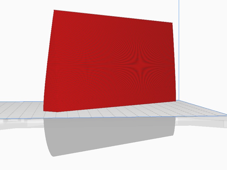

Test wing printed but not yet glued together.

Techniques miles beyond anything I can do.
My on;y observation is printing does have a grain and is about 5 times strong along the line of the bead than across it.
How much stronger would the wing be if the bead lines could be laid along the span of the wing rather than across it.
It could be lighter to have a single strong spar, skin and ribs.
Nothing like as sophisticated as yours but this is as far as I got.
Front and rear parts of the wing printed with ribs.
Test wing printed but not yet glued together.
Attachments:
Last edit: 28 Feb 2025 21:53 by Quorneng.
Thanks: Klipkopwildlife, jon.in.swansea
Please Log in or Create an account to join the conversation.
- jon.in.swansea
-
- Offline
- Elite Member
-
Less
More
- Posts: 750
- Thank you received: 1147
01 Mar 2025 09:59 #102
by jon.in.swansea
Replied by jon.in.swansea on topic 3D printing Widgets
I agree it would be great to not have to print a wing vertically. I think you might be on to something....
So to turn it 90 degrees and instead of doing the 0.5mm offset bodies as spars could that be done with 0.5mm offset ribs?
Probably needs a sketch (below)....assuming the wing is split into a front portion in front of the main spar and a trailing section, the ribs could be essentially vase printed with the grain along the length of the wing. This arrangement would support some curve in the wing along its length as well as a tapering section.

Considering the 'join between the front and trailing portions of the wing we have a choice. Simplest would be for a flat join with max surface area for gluing. Perhaps print with 2-3 base layers to get a bit more stiffness perhaps with a notch to take a normal PLA strip ~1-2mm thick, 5mm wide and as long as possible to provide the flanges of the spar or just a length of balsa or CF to form outer flanges...
Or rather than more base layers to beef up a main spar - just create a spar shape to match the wing and print it in PLA or PETG and print it ~1mm thick and sandwitch it between the front and trailing halves...
Probably want the ribs expressing themselves on the upper face of the wing so that the bottom has the cleanest run of filament. Will printing it 90 degrees rotated allow the printed skin to adequately take the compre
I will give that a try.
So to turn it 90 degrees and instead of doing the 0.5mm offset bodies as spars could that be done with 0.5mm offset ribs?
Probably needs a sketch (below)....assuming the wing is split into a front portion in front of the main spar and a trailing section, the ribs could be essentially vase printed with the grain along the length of the wing. This arrangement would support some curve in the wing along its length as well as a tapering section.
Considering the 'join between the front and trailing portions of the wing we have a choice. Simplest would be for a flat join with max surface area for gluing. Perhaps print with 2-3 base layers to get a bit more stiffness perhaps with a notch to take a normal PLA strip ~1-2mm thick, 5mm wide and as long as possible to provide the flanges of the spar or just a length of balsa or CF to form outer flanges...
Or rather than more base layers to beef up a main spar - just create a spar shape to match the wing and print it in PLA or PETG and print it ~1mm thick and sandwitch it between the front and trailing halves...
Probably want the ribs expressing themselves on the upper face of the wing so that the bottom has the cleanest run of filament. Will printing it 90 degrees rotated allow the printed skin to adequately take the compre
I will give that a try.
Attachments:
Thanks: Klipkopwildlife, Quorneng
Please Log in or Create an account to join the conversation.
- Quorneng
-
- Offline
- Forum Master
-
Less
More
- Posts: 10058
- Thank you received: 19042
01 Mar 2025 15:50 #103
by Quorneng
Replied by Quorneng on topic 3D printing Widgets
jon
Yes I had envisioned the base of each half would be either half a true spar section or possibly half a box section with an appropriate infill.
Now if you had double nozzles it would be possible to print a spar with a high strength top and bottom flanges to the spar.
Having looked at the test wing I printed it seems I did a third option.with the front section as a "D" spar.
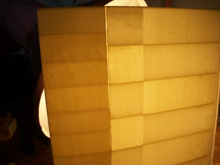
The front section has more ribs and a double thickness skin whereas the aft is as light as possible with a single skin.As the front has all the strength the two parts are simply glued together.
The test wing has a span of 8" and a chord of 5".
It is very stiff.
Yes I had envisioned the base of each half would be either half a true spar section or possibly half a box section with an appropriate infill.
Now if you had double nozzles it would be possible to print a spar with a high strength top and bottom flanges to the spar.
Having looked at the test wing I printed it seems I did a third option.with the front section as a "D" spar.
The front section has more ribs and a double thickness skin whereas the aft is as light as possible with a single skin.As the front has all the strength the two parts are simply glued together.
The test wing has a span of 8" and a chord of 5".
It is very stiff.
Attachments:
Thanks: Klipkopwildlife, jon.in.swansea
Please Log in or Create an account to join the conversation.
- jon.in.swansea
-
- Offline
- Elite Member
-
Less
More
- Posts: 750
- Thank you received: 1147
02 Mar 2025 07:45 #104
by jon.in.swansea
Replied by jon.in.swansea on topic 3D printing Widgets
Ah, interesting idea on shifting the density of ribs on leading and trailing.
I took that complex wing form and have setup a variant with vase printed ribs, leading and trailing. I learned quite a bit about the sequencing of CAD actions and also the offsets to the ribs needed to get the slicer to work in vase mode.
I will attempt to print the leading edge this morning. I several ideas about the spar and mixes of materials is going to be more or less hassle vs strength. This is great fun. When I have a path through the maze I will post something.
I took that complex wing form and have setup a variant with vase printed ribs, leading and trailing. I learned quite a bit about the sequencing of CAD actions and also the offsets to the ribs needed to get the slicer to work in vase mode.
I will attempt to print the leading edge this morning. I several ideas about the spar and mixes of materials is going to be more or less hassle vs strength. This is great fun. When I have a path through the maze I will post something.
Thanks: Klipkopwildlife, Quorneng
Please Log in or Create an account to join the conversation.
- Quorneng
-
- Offline
- Forum Master
-
Less
More
- Posts: 10058
- Thank you received: 19042
02 Mar 2025 09:32 #105
by Quorneng
Replied by Quorneng on topic 3D printing Widgets
As the wing has to be printed across the bed which in my case limits the length of each section I wondered about the best way to glue sections together particularly with a "D" box wing.In a D box all the strength and stiffness is due to the skin so the skin to skin joint has to be all round and with sufficient glue area to ensure it is as strong in both tension and shear as the rest of the skin. This is what I came up with.
Each wing section ends in either a "plug" or "socket" to give an overlapping glue joint with the minimum extra material.

Special parts to create dihedral and a wing tip could be plugged in the same way. I haven't actually printed anything yet so there may be problems..
Each wing section is likely to take some time to print so a 1.4m span wing made up of 14 x 200mm long sections (7 front and 7 rear) will take a day or two!
I estimate such a 1.4m wing in LW-PLA would weigh about 150g bare.
Not too bad but it would likely be a bit lighter using proper foam!

Jon as your Free Cad techniques are way beyond mine I can only say well done and keep going.
Each wing section ends in either a "plug" or "socket" to give an overlapping glue joint with the minimum extra material.
Special parts to create dihedral and a wing tip could be plugged in the same way. I haven't actually printed anything yet so there may be problems..
Each wing section is likely to take some time to print so a 1.4m span wing made up of 14 x 200mm long sections (7 front and 7 rear) will take a day or two!
I estimate such a 1.4m wing in LW-PLA would weigh about 150g bare.
Not too bad but it would likely be a bit lighter using proper foam!
Jon as your Free Cad techniques are way beyond mine I can only say well done and keep going.
Attachments:
Thanks: Klipkopwildlife, jon.in.swansea
Please Log in or Create an account to join the conversation.
Time to create page: 1.606 seconds